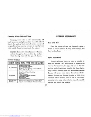
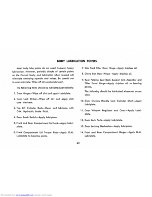
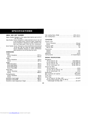
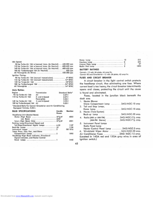
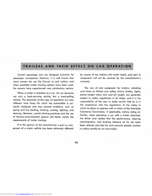
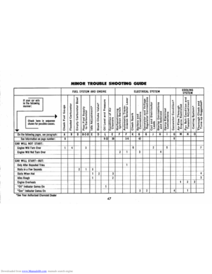
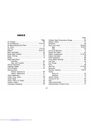
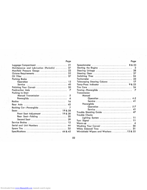
Page 9 of 56

Downloaded from www.Manualslib.com manuals search engine more economical cruising gear in the shortest possible
time. Hard acceleration for fast starts will cause the trans
mission to remain in low gear for a considerably longer
period.
When driving at speeds below 45 mph, the transmis
sion may be shifted back into low range for extra acceler
ation for passing by depressing the accelerator pedal
fully. The transmission will automatically shift back into cruising
gear when the accelerator pedal is momentarily
released.
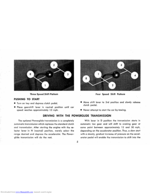
PUSHING TO START
• Turn off all
electrical loads such as radio, heater and,
if possible, lights until the engine starts.
• Turn on key and move selector lever to neutral. At
20 to 25 mph move lever to l.
• When engine starts, move selector lever to D.
NOTE: Never tow to start.
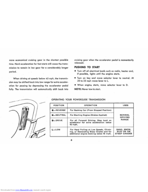
OPERATING YOUR POWERGLIDE TRANSMISSION
POSITION OPERATION USES
R-REVERSE For Backing Car (From Stopped Position)
N-NEUTRAL For Starting Engine (Brakes Applied) NORMAL DRIVING
D-DRIVE For all Forward Driving. Step hard on RANGE
accelerator for extra acceleration below 45 mph.
L-LOW For Hard Pulling at Low Speeds, Climb-SAND, SNOW, ing, or Descending Steep Grades and for MUD OR ON additional engine braking below 40 mph. STEEP GRADES
6
Page 10 of 56

Downloaded from www.Manualslib.com manuals search engine TOWING
• Place selector lever in neutral.
• If transmission or axle are malfunctioning, tow with
rear wheels raised.
• When towing any vehicle on its front wheels, the
steering wheel should be secured to maintain a
straight forward position .
• Never tow faster than 50 mph.
ROCKING CAR
When stuck in mud, sand or snow, you may rock
the car by depressing the accelerator slightly and shift
ing the selector lever between Rand D. Avoid excessive
engine speed while performing this operation.
PARKING CAR
It is important that when your Corvair is parked the
parking brake be fully engaged. Do not count on the
transmission to hold the car. Always engage the parking
brake when parked.
POWERGLIDE DRIVING CAUTIONS
• Always engage parking brake when parked.
• Do not accelerate engine in L, 0, or R with
the brakes engaged. This can cause damage
by overheating transmission.
• Do not hold car on an upgrade by accelerat
ing engine. Use brakes.
• Use low position for hard pulls at low
speed, climbing or descending steep grades
and for push starting.
• Always stop car before shifting to reverse.
DRIVING WITH POSITRACTION REAR AXLE
The Positraction rear axle gives you constant driv
ing force on both r~ar wheels; especially helpful in the
winter and during other slippery driving conditions.
In normal use, light throttle application will supply
7
maximum traction. When starting with one rear wheel
on an excessively slippery surface, slight application of
the parking brake may be necessary to gain maximum
traction.
Page 11 of 56

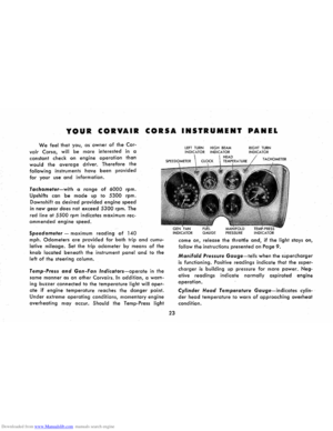
Downloaded from www.Manualslib.com manuals search engine INSTRUMENTS
All driving instruments are grouped in the instrument
cluster
which is located immediately in front of the driver
to provide quick reading and maximum convenience and
accessibility. The TEMP-PRESS and GEN-FAN indicators
provide important information concerning the condition
of the engine and should be observed regularly during
operation of the car. The information on these pages
will help you understand the operation of these instru
ments. The illustrations here
and on page 10 will ac
quaint you with the instrument cluster and the instrument
panel as a whole.
FUEL GAUGE
This electrically operated
gauge accurately indicates
the amount of fuel in the fuel
tank only when the ignition
switch is in the ON position.
When the ignition is "off",
the indicator pointer will not
necessarily return to the
empty IE) mark, but may stop
8
at any point on the gauge. Therefore, always be sure
that the ignition switch is "on" when reading the fuel
gauge.
SPEEDOMETER
Conveniently located in the instrument cluster di
rectly ahead of the driver, the speedometer shows at a
glance the speed of the car in miles per hour. The
odometer, encircled within the speedometer dial, reg
isters accumulated vehicle mileage.
Page 12 of 56

Downloaded from www.Manualslib.com manuals search engine TEMP-PRESS AND GEN-FAN INDICATORS
These indicators provide a check on the operating
condition of the engine and the generator. Both indi
cators should light with the ignition switch ON before
starting the engine and should go out after the engine
is started. The lights should remain out while engine is
operating, except the GEN-FAN indicator may flicker
when
engine is idling.
CAUTION: If either of these indicators light
while car is
being driven, immediately follow the
procedure outlined under "EMERGENCY OPER
ATING INSTRUCTIONS," so car may be driven
to
the nearest service facility.
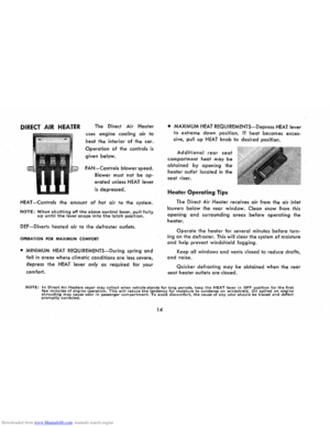
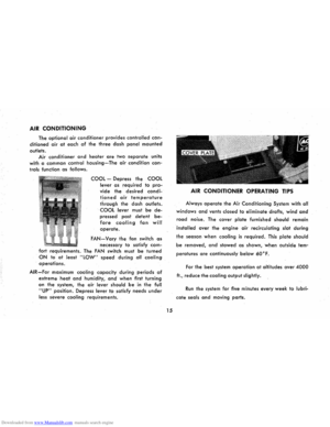
EMERGENCY OPERATING INSTRUCTIONS
(To be followed if either
TEMP-PRESS or GEN-FAN indi
cators light while car is being
driven.)
1.
Set heater FAN and HEAT
controls to full "ON" positions.
(If
equipped with air conditioning, turn air condi
tioning COOL switch to OFF.)
9
NOTE: After setting the heater controls, leave
them in that position until cause of trouble is
corrected ..
2. Stop the car as soon as driving conditions permit.
Turn ignition key to
OFF to stop engine but turn
key
back to ON so heater blower will continue
to cool engine.
3. Check for broken fan belt or belt off pulleys or
engine low oil level. If only GEN-FAN indicator
is lighted, belt is not broken or off pulleys and en
gine oil level is satisfactory, car can be driven at
slow speeds; however, generator must be checked
and serviced as soon as possible.
4. If trouble is found to be a broken fan belt or belt
off pulleys, wait approximately five minutes, start
engine and drive car at no more than 25 miles per
hour until TEMP-PRESS indicator comes on, then
repeat Step 2.
NOTE: The GEN-FAN indicator will stay on until
fan
belt is installed .
5. Repeat Step 4 as necessary until facility is reached
where fan belt can be installed.
Page 13 of 56
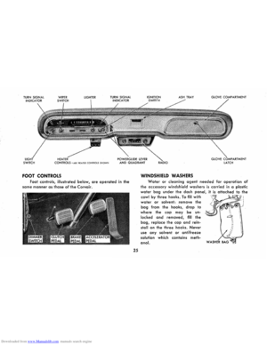
Downloaded from www.Manualslib.com manuals search engine I
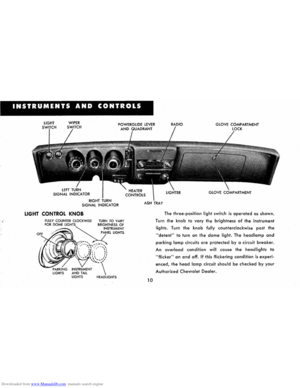
INSTRUMENTS AND CONTROLS
LIGHT WIPER RIGHT
TURN SIGNAL INDICATOR
LIGHT CONTROL KNOB
PARKING LIGHTS
TURN TO VARY
LIGHTER
GLOVE COMPARTMENT
LOCK
GLOVE COMPARTMENT
ASH
TRAY
10
The three-position light switch is operated as shown.
Turn the
knob to vary the brightness of the instrument
lights. Turn the knob fully counterclockwise past the
"detent" to turn on the dome light. The headlamp and
parking lamp circuits are protected by a circuit breaker.
An overload condition will cause the headlights to
"flicker" on and off. If this flickering condition is experi
enced, the head lamp circuit should be checked by your
Authorized Chevrolet Dealer.
Page 14 of 56
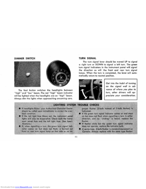
Downloaded from www.Manualslib.com manuals search engine DIMMER SWITCH
The foot button switches the headlights between
"high" and "low" beam. The red "high" beam indicator
will be lighted when the headlights are on "high" beam.
Always dim the lights when approaching oncoming cars.
11
TURN SIGNAL
The turn signal lever should be moved UP to signal
a right turn or DOWN to signal a left turn. The green
turn signal indicators in the instrument panel will signal
the direction as will the front and rear turn signal
lamps. When the turn is completed, the lever will auto
matically return to neutral position.
Get into the habit of turning
on the signal well in ad
vance of where you plan to
turn, other drivers will ap
preciate your consideration.
Page 15 of 56
, the clutch pedal
(manual transmi")
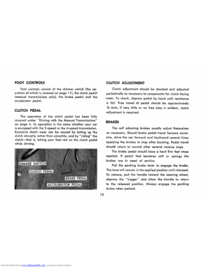
Downloaded from www.Manualslib.com manuals search engine FOOT CONTROLS
Foot controls consist of the dimmer switch (the op
eration of which is covered on page 11), the clutch pedal
(manual transmissions only), the brake pedal and the
accelerator pedal.
CLUTCH PEDAL
The operation of the clutch pedal has been fully
covered under "Driving with the Manual Transmissions"
on
page 4. Its operation is the same whether your car
is equipped with the 3-speed or the 4-speed transmission.
Excessive clutch
wear can be caused by letting up the
clutch abruptly rather than smoothly, and by "riding" the
clutch-that is, letting your foot rest on the clutch pedal
while driving.
12
CLUTCH ADJUSTMENT
Clutch adjustment should be checked and adjusted
periodically as necessary to compensate for clutch facing
wear. To check, depress pedal by hand until resistance
is felt. Free travel of pedal should be approximately
% -inch; if very little or no free play is evident, clutch
adjustment
is required.
BRAKES
The self adjusting brakes usually adjust themselves
as necessary. Should brake pedal travel become exces
sive, drive
the car forward and backward several times
applying the brakes to stop after backing. Pedal travel
should
return to normal after several reverse stops
The
brake pedal should have a hard firm feel when
applied. If pedal feel becomes soft or spongy the
brakes are in need of service.
Pull the parking brake lever to engage the brake.
The lever will remain in the applied position until released.
To release, pull the handle toward the steering wheel,
depress the "trigger" and allow the handle to return
to the released position. Always engage the parking
brake when parked.
Page 16 of 56
 parallel
acting wipers are operated by means of the wiper con�")
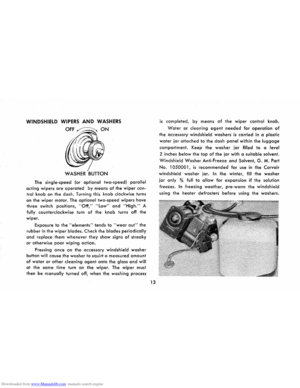
Downloaded from www.Manualslib.com manuals search engine WINDSHIELD WIPERS AND WASHERS
OFF~ON
The single-speed (or optional two-speed) parallel
acting wipers are operated by means of the wiper con
trol knob on the dash. Turning this knob clockwise turns
on the
wiper motor. The optional two-speed wipers have
three switch positions, "Off," "Low" and "High." A
fully counterclockwise turn of the knob turns off the
wiper.
Exposure
to the "elements" tends to "wear out" the
rubber in the wiper blades. Check the blades periodically
and replace them whenever they show signs of streaky
or otherwise poor wiping action.
Pressing once on the accessory windshield washer
button will cause the washer to squirt a measured amount
of water or other cleaning agent onto the glass and will
at the same time turn on the wiper. The wiper must
then
be manually turned off, when the washing process
13
is completed, by means of the wiper control knob.
Water or cleaning agent needed for operation of
the accessory windshield washers is carried in a plastic
water jar attached to the dash panel within the luggage
compartment. Keep the washer jar filled to a level
2 inches below the top of the jar with a suitable solvent.
Windshield Washer Anti-Freeze and Solvent, G. M. Part
No. 1050001, is recommended for use in the Corvair
windshield washer jar. In the winter, fill the washer
jar only 3,4 full to allow for expansion if the solution
freezes. In freezing weather, pre-warm the windshield
using the heater defrosters before using the washers.