Page 25 of 56

Downloaded from www.Manualslib.com manuals search engine CORVAIR CORSA
The Corvair Corsa models are operated and main
tained as outlined for the regular Corvair. Additional
instrumentation and operating instructions peculiar to
Corsa models only are reviewed in the following pages.
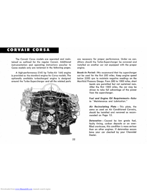
A high-performance (140 hp Turbo-Air 164) engine
is provided as the standard engine for Corsa models. The
optionally available turbocharged engine is designed
around the Turbo-Supercharger and all the related parts
22
are necessary for proper performance. Under no con
ditions should the Turbo-Supercharger be removed and
installed on another car not equipped with the proper
engine.
Break-In Period-We recommend that the supercharger
not be used for the first 500 miles. Keep engine speed
below 2500 rpm to maintain negative readings on the
Manifold Pressure Gauge. From 500 to 1000 miles, short
bursts
are permitted but not sustained runs.
After the first 1000 miles, the car may be
driven to take full advantage of the power
from the supercharger.
Fuel and Engine Oil Requirements~Refer
to "Maintenance and Lubrication."
Air Recirculating Plate -This plate, the
same as used on
Air Conditioned Corvairs,
should be installed and removed as recom
mended on Page 15.
Detonation -Caused by low grade fuel,
faulty timing, carbon deposits or an over
filled crankcase, this condition is more serious
than on other engines. If detonation occurs
have your car checked by your Chevrolet
Dealer.
Page 26 of 56

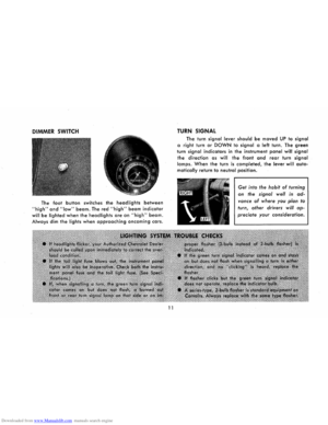
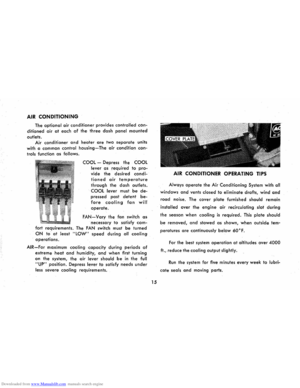
Downloaded from www.Manualslib.com manuals search engine YOUR CORVAIR CORSA INSTRUMENT PANEL
We feel that you, as owner of the Cor-
vair Corsa, will be more interested in a
constant check on
engine operation than
would the average driver. Therefore the
following instruments have been provided
for your use and information.
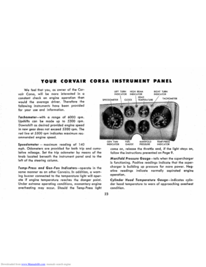
Tachometer-with a range of 6000 rpm.
Upshifts can
be made up to 5300 rpm.
Downshift as desired provided engine speed
in
new gear does not exceed 5300 rpm. The
red
line at 5500 rpm indicates maximum rec
ommencled
engine speed.
Speedometer -maximum reading of 140
mph. Odometers are provided for both trip and cumu
lative mileage. Set the trip odometer by means of the
knob located beneath the instrument panel and to the
left of the steering column.
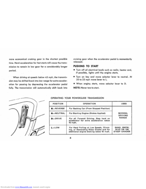
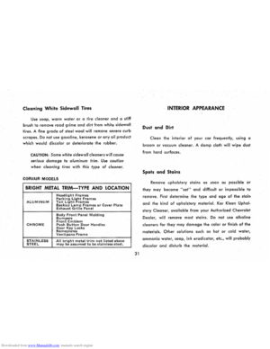
Temp-Press and Gen-Fan Indicators-operate in the
same
manner as on other Corvairs. In addition, a warn
ing buzzer connected to the temperature light will oper
ate if engine temperature reaches the danger point.
Under extreme operating conditions, momentary engine
overheating may occur. Should the Temp-Press light
23
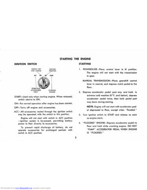
lEFT TURN HIGH BEAM INDICATOR INDICATOR
GAUGE PRESSURE
RIGHT TURN INDICATOR
come on, release the throttle and, if the light stays on,
follow the instructions presented on Page 9 .
Manifold Pressure Gauge-tells when the supercharger
is functioning. Positive readings indicate that the super
charger is building up pressure for more power. Neg
ative readings indicate normally aspirated engine
operation.
Cylinder Head Temperature Gauge-indicates cylin
der head temperature to warn of approaching overheat
condition.
Page 27 of 56

Downloaded from www.Manualslib.com manuals search engine CORVAIR GREENBRIER
INSTRUMENTS AND CONTROLS
The Corvair Greenbrier instr~ments and controls are
essentially the same as those of the Covair which are de
scribed in preceding pages of this book. However, due to
body construction, various items differ somewhat in
operation and location. The next few pages cover those
items
peculiar to the Corvair Greenbrier only.
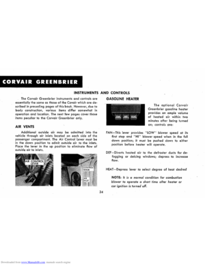
AIR VENTS
Additional outside air may be admitted into the
vehicle through air inlets located on each side of the
passenger compartment. The Air Control Lever must be
in the down position to admit outside air to the inlets.
Place
the lever in the up position to eliminate flow of outside air to inlets.
24
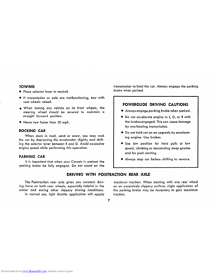
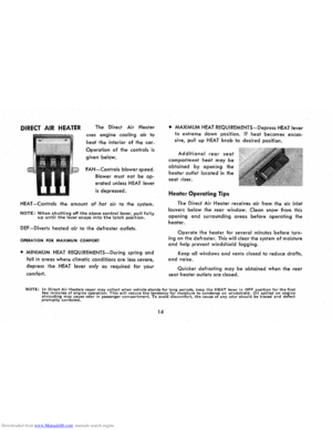
GASOLINE HEATER
The optional Corvair
Greenbrier gasoline heater
provides an ample volume
of heated air within two
minutes
after being turned
on; controls are:
FAN-This lever provides "LOW" blower speed at its
first
stop and "HI" blower speed when in the full
down position; it must be pushed down to either
position before heater will operate.
DEF-Diverts heated air to the defroster ducts for de
fogging or deicing windows; depress to increase
flow.
HEAT -Depress lever to select degree of heat desired
NOTE: It is a normal condition for combustion
blower to operate
a short time after heater or
car ignition
is turned off.
Page 28 of 56
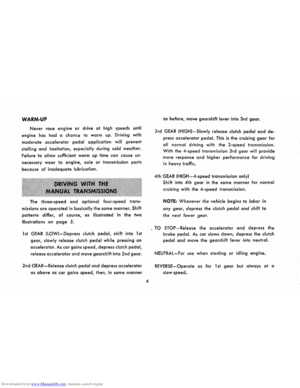
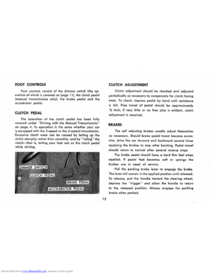
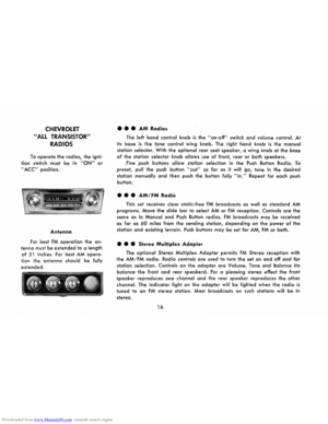
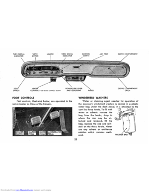
Downloaded from www.Manualslib.com manuals search engine SWITCH CONTROLS -AIR HEATER C
ONTROL S SH OWN
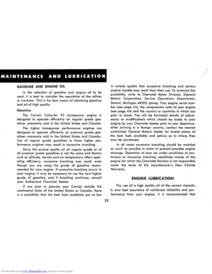
FOOT CONTROLS
Foot controls, illustrated below, are operated in the
same
manner as those of the Corvair.
25
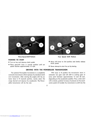
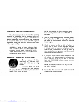
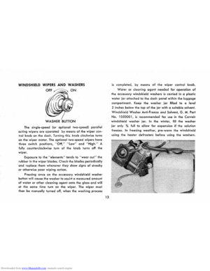
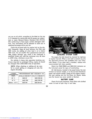
ASH TRAY
WINDSHIELD WASHERS
GLOVE ARTMENT
GLOVE COMPARTMENT
LATCH
Water or cleaning agent needed for operation of
the accessory windshield washers is carried in a plastic
water bag under the dash panel, it is attached to the
cowl by three hooks. To flll with
water or solvent: remove the
bag from the hooks, drop to
where the cap may be un
locked and removed, flll the
bag, replace the cap and rein
stall on the three hooks. Never
use any solvent or antifreeze
solution which contains meth
anol.
Page 29 of 56
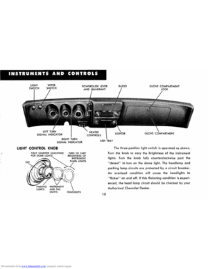
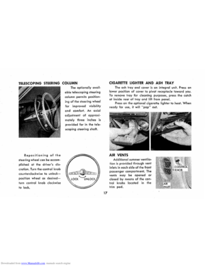
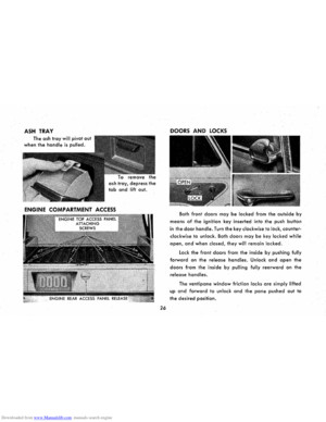
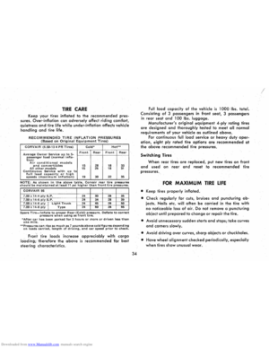
Downloaded from www.Manualslib.com manuals search engine ASH TRAY
The ash tray will pivot out
when the handle is pulled.
ash tray, depress the
tab and lift out.
ENGINE COMPARTMENT ACCESS
26
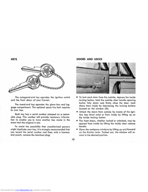
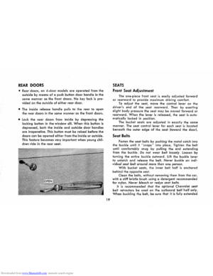
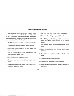
DOORS AND LOCKS
Both front doors may be locked from the outside by
means of the ignition key inserted into the push button
in the door handle. Turn the key clockwise to lock, counter
clockwise
to unlock. Both doors may be key locked while
open, and when closed, they will remain locked.
lock the front doors from the inside by pushing fully
forward on the release handles. Unlock and open the
doors from the inside by pulling fully rearward on the
release handles.
The ventipane window friction locks are simply lifted
up and forward to unlock and the pane pushed out to
the desired position.
Page 30 of 56

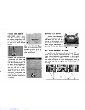
Downloaded from www.Manualslib.com manuals search engine DOUBLE SIDE DOORS
FRONT SIDE DOOR -Open
from the outside by turning
the handle downward and
from the inside by pulling to
the
rear on the inside release
handle.
REAR SIDE DOOR-Open
(after the front side has been
opened) by means of the re
lease handle located on the
inner
door panel.
LOCKING THE SIDE DOORS
-After both side doors are
closed, they may be locked
from
the inside by means of
the push button located on
the foremost part of the win
dow sill. The lock is con
veniently locoted for acces
sibility by
the driver. Visual
indication precludes the
necessity of checking opera
tion of the doors to see if they
are locked.
27
DOUBLE REAR DOORS
The rear doors operate in
much the same manner as the
side doors, but lock and un
lock at the door handle push
button
release only. No inner
door locking mechanism is
provided for the rear doors.
FULL DOOR OPENING FEATURE
Special door checks normally permit each side and
rear door to open to a maximum of 95°. By removing
these checks from their retaining slots in the doors, a full
180° opening of each of these doors is possible. When
the doors are closed the check automatically enters its
slot
in the door thus setting the door for its normal 95°
opening.
Page 31 of 56
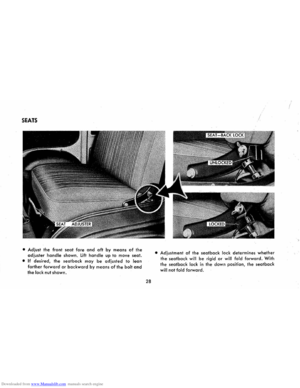
Downloaded from www.Manualslib.com manuals search engine SEATS
• Adjust the front seat fore and aft by means of the
adjuster handle shown. Lift handle up to move seat.
• If desired, the seatback may be adjusted to lean
farther forward or backward by means of the bolt and
the lock nut shown.
28
• Adjustment of the seatback lock determines whether
the seatback will be rigid or will fold forward. With
the seatback lock in the down position, the seatback
will not fold forward.
Page 32 of 56
Downloaded from www.Manualslib.com manuals search engine I
t
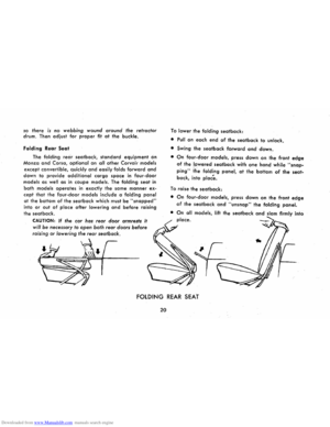
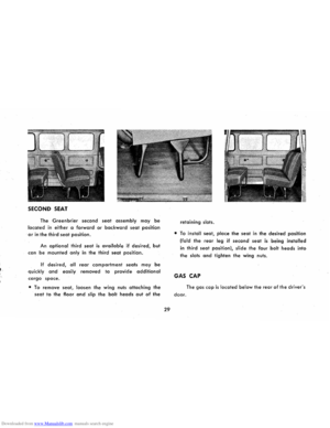
SECOND SEAT
The Greenbrier second seat assembly may be
located in either a forward or backward seat position
. or in the third seat position.
An optional third seat is available if desired, but
can be mounted only in the third seat position.
If desired, all rear compartment seats may be
quickly and easily removed to provide additional
cargo space.
• To remove seat, loosen the wing nuts attaching the
seat to the floor and slip the bolt heads out of the
29 retaining
slots.
•
To install seat, place the seat in the desired position
(fold the rear leg if second seat is being installed
in third seat position), slide the four bolt heads into
the
slots and tighten the wing nuts.
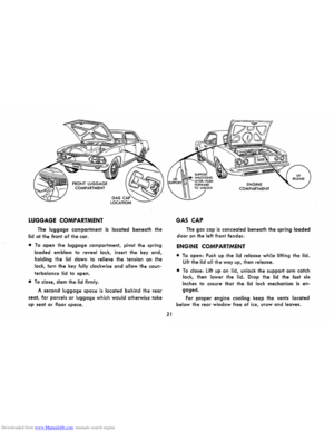
GAS CAP
The gas cap is located below the rear of the driver's
door.