1900 MITSUBISHI DIAMANTE Power steering
[x] Cancel search: Power steeringPage 162 of 408
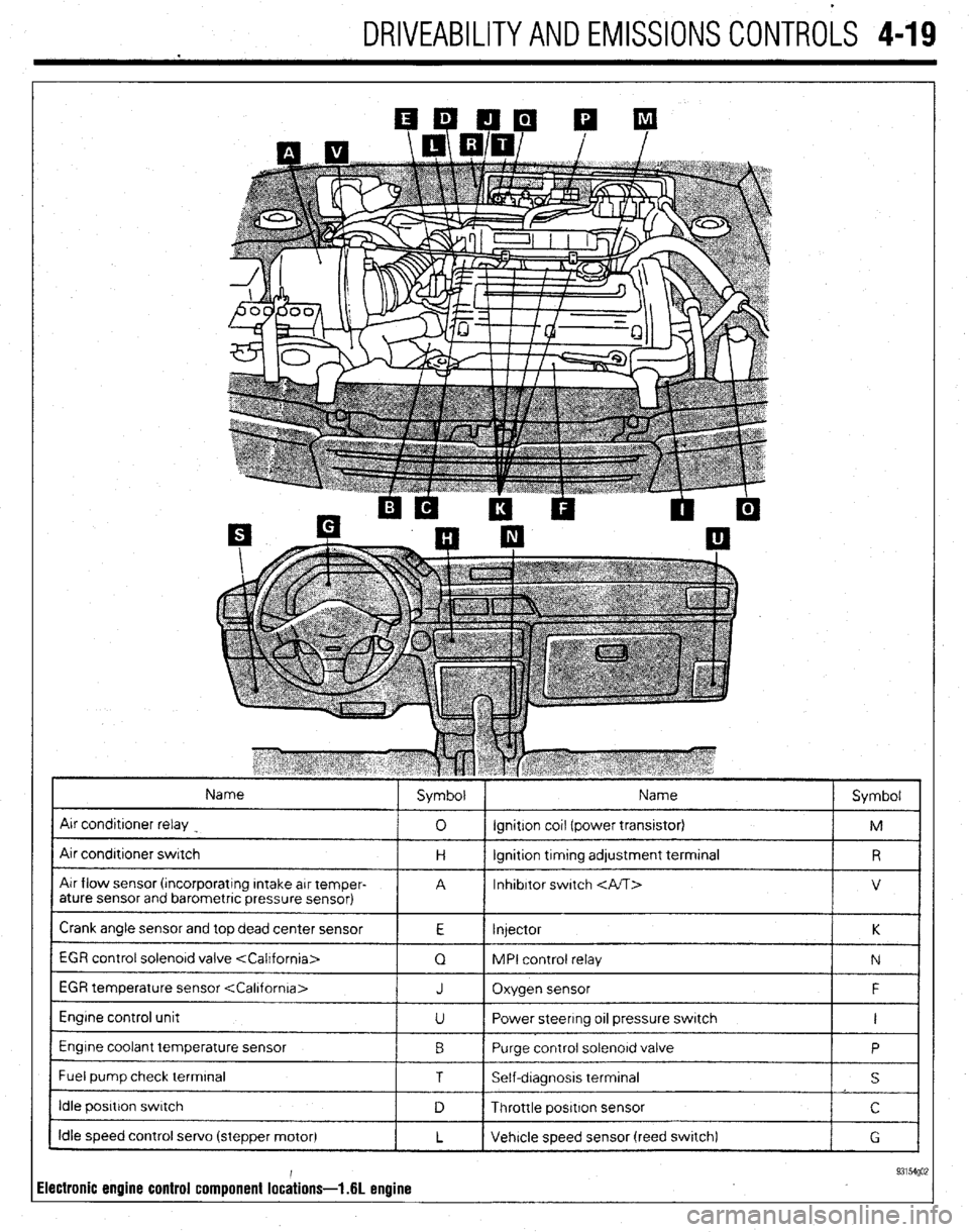
DRIVEABILITYAND EMISSIONS CONTROLS 4-19
Name
Air conditroner relay
Air condrtroner switch
Air flow sensor (rncorporatrng Intake arr temper-
ature sensor and barometric pressure sensor) Symbol Name
Symbol
0 ignition cot1 (power transrstor)
M
H lgnrtion trmtng adjustment terminal
R
A Inhibitor switch
V
Crank angle sensor and top dead center sensor
E Injector K
1 EGR control solenord valve
1 Q 1 MPI control relay
1 N 1
EGR temperature sensor
Engine control unit
Engine coolant temperature sensor
I Fuel pump check terminal J Oxygen sensor F
U Power steering 011 pressure switch I
0 Purge control solenord valve
P
1 T I Self-dragnosis terminal
I s I
I idle posrtron swatch
1 D 1 Throttle positron sensor I c I
Idle speed control servo (stepper motor)
L Vehicle speed sensor (reed swatch)
G
ilectronic engine control component lochions- .6L enuine 93154go;
Page 163 of 408
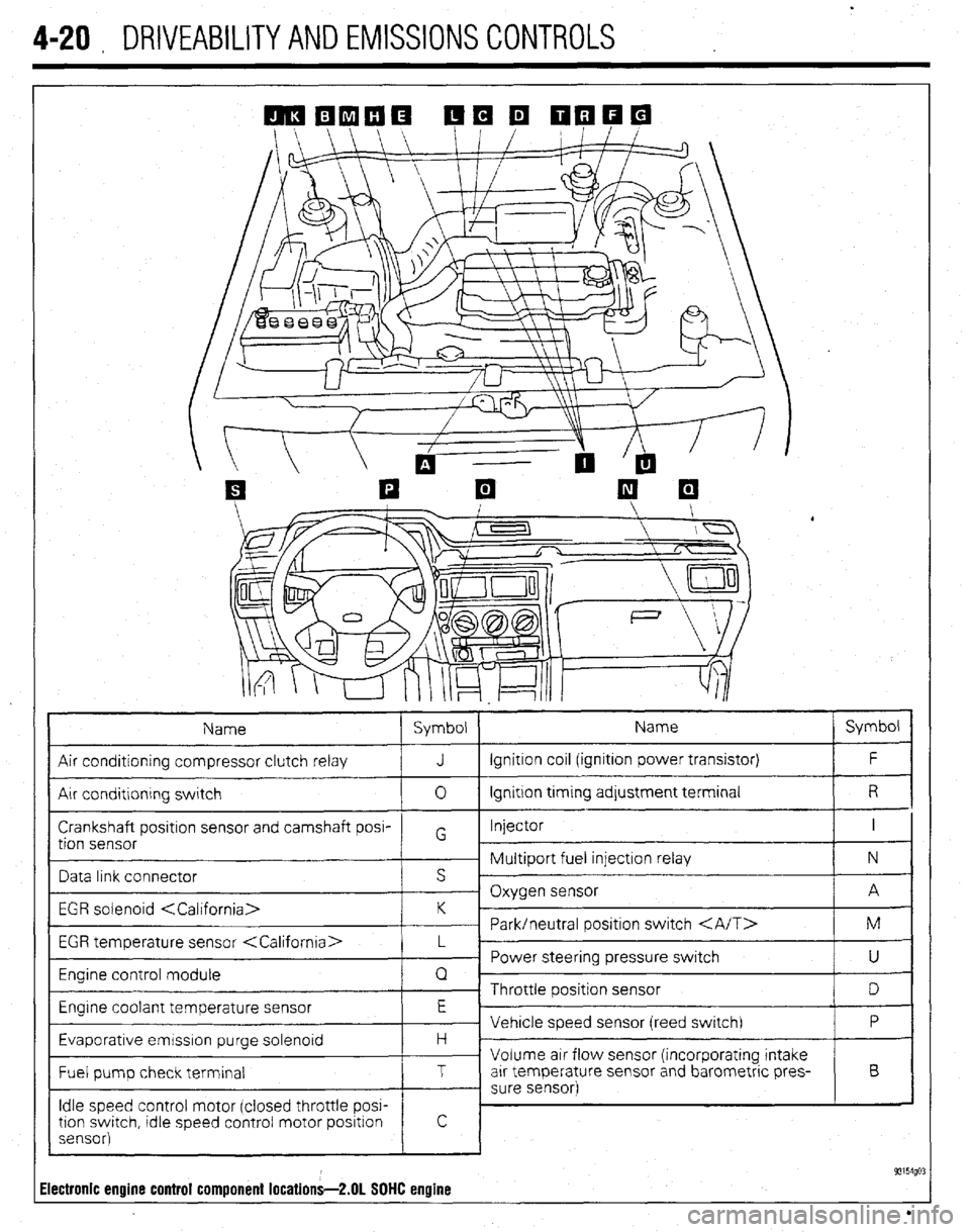
4-20 , DRIVEABILITYAND EMISSIONS CONTROLS
Name Symbol Name Symbol
Air conditioning compressor clutch relay J Ignition coil (ignition power transistor) F
Air conditlonrng switch 0 Ignition trming adjustment terminal R
Crankshaft positron sensor and camshaft posi- Injector I
tion sensor G
~ Multiport fuel injection relay N
Data link connector s ’
- Oxygen sensor A
EGR solenoid
~ Park/neutral positron switch M
EGR temperature sensor
_ Power steering pressure switch
U
Engine control module Q
~ Throttle position sensor
D
Engrne coolant temperature sensor E
Vehicle speed sensor (reed switch) P
Evaporative emrsslon purge solenoid H -
Volume air flow sensor (incorporating intake
Fuel pump check terminal T arr temperature sensor and barometric pres- B
- sure sensor)
Idle speed control motor (closed throttle POW
tron swatch, tdle speed control motor positron
sensor)
! c
93154go: Electronic engine control component locations-2.01 SOHC engine
Page 165 of 408
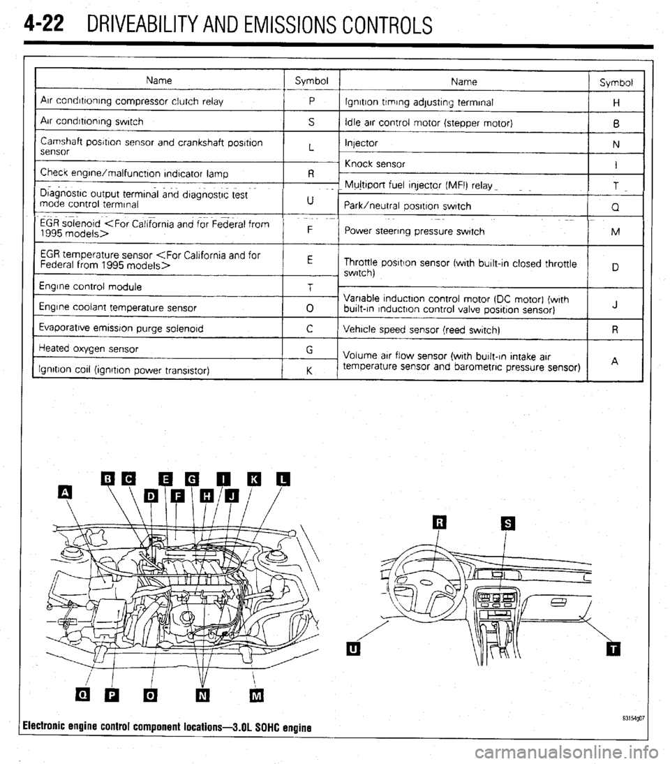
4-22 DRIVEABILITYAND EMISSIONS CONTROLS
Name Symbol
Name Symbol
I
Arr condrttontng compressor clutch relay
P lgnrtton trmrng adjustrng terminal
H
Air condrbonrng swrtch
S Idle arr control motor (stepper motor)
B
Camshaft posrtron sensor and crankshaft posrtron
Injector
N
sensor L
~ Knock sensor
Check engrne/malfunctton rndtcator lamp I
R -
I D~agnostrc output termtnal and dtagnostrc test F- Mujttport fuel qector (MFI) relay _
T
mode control termrnal U
Park/neutral oosrtron swatch
Q
EGR solenoid
1995 models> F
Power steering pressure swatch M
I
EGR temperature sensor
Throttle posrtlon sensor fwrth burlt-In closed throttle
, swrtch)
Engrne control module
Engine coolant temperature sensor
Evaporatrve emrssron purge solenord T
0 Variable tnductton control motor (DC motor) (wrth
burlt-tn rnductron control valve posrtron sensor) J
C Vehrcle speed sensor (reed swatch) R
Heated oxygen sensor
Ignition cot1 (ionrtron Dower transistor) G
Volume arr flow sensor (with burlt-In Intake arr
K temperature sensor and barometric pressure sensor)
I I A
ilectronic engine control component locations-3.01 SOHC engine 93154go7
Page 167 of 408
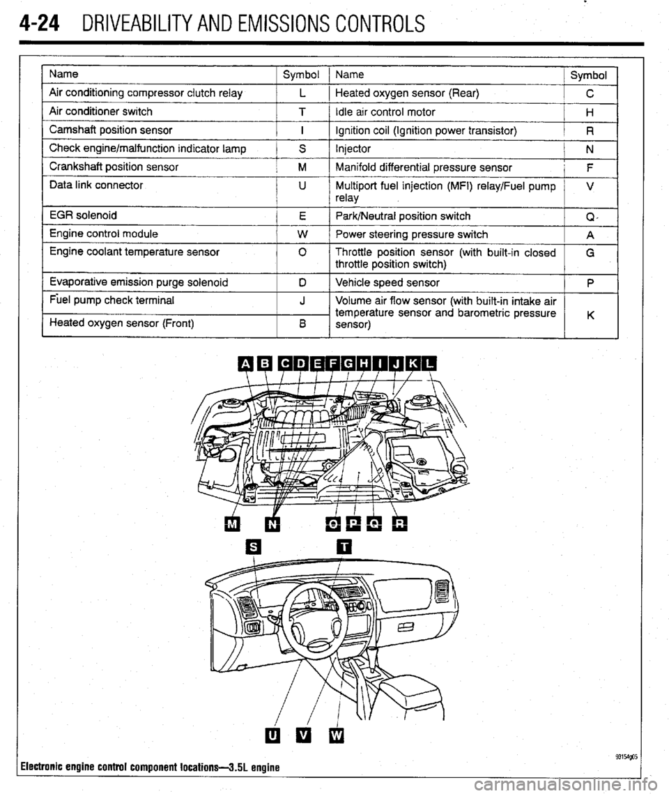
.
4-24 DRIVEABILITYAND EMISSIONS CONTROLS
Name
Air conditioning compressor clutch relay
Air conditioner switch
Camshaft position sensor
Check engine/malfunction indicator lamp
Crankshaft position sensor
Data link connector
EGR solenoid
Engine control module
Engine coolant temperature sensor
Evaporative emission purge solenoid
Fuel pump check terminal
Heated oxygen sensor (Front) Symbol 1 Name
Symbol
L 1 Heated oxygen sensor (Rear)
C
T / Idle arr control motor
H
I ignition coil (Ignition power transistor)
R
S Injector
N
M Manifold differential pressure sensor
F
U Multiport fuel injection (MFI) relay/Fuel pump V
relay
E Park/Neutral position switch
Q,
W Power steering pressure switch
A
0 Throttle position sensor (with built-in closed
G
throttle position switch)
D Vehicle speed sensor
P
J Volume air flow sensor (with built-in intake air
temperature sensor and barometric pressure
B K
sensor)
ilectronic engine control component locations-3.51 engine
Page 168 of 408
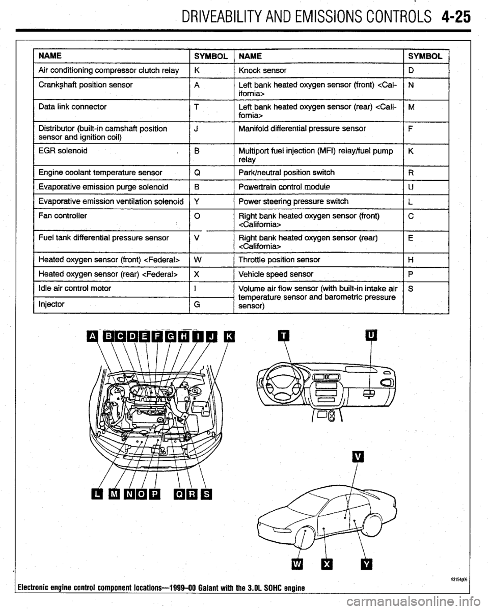
DRIVEABILITYAND EMISSIONS CONTROLS 4-25
NAME
SYMBOL NAME SYMBOL
Air conditioning compressor clutch relay K
Knock sensor D
I Crankshaft position sensor
A Left bank heated oxygen sensor (front)
I I
Data link connector T Left bank heated oxygen sensor (rear)
I Distributor (built-in camshaft position
I J Manifold differential pressure sensor
I F
sensor and ignition coil)
I
EGR solenoid . B Multiport fuel injection (MFI) relay/fuel pump K
relay
1 Engine coolant temperature sensor
IQ 1 Park/neutral position switch IR
Euaporatiue.emission purge solenoid B
Powertraincontrol module LJ
l Evaporatiw5+eiiission ventilation solenoid Y
I Powersteering pressure switch
L
Fan controller 0 Right bank heated oxygen sensor (front) C
Fuel tank differential pressure sensor V Right bank heated oxygen sensor (rear) E
Heated oxygen sensor (front)
I
1 Heated oxygen sensor (rear)
Ip I
Idle air control motor
Injector I
G Volume air flow sensor (with built-in intake air S
temperature sensor and barometric pressure
sensor)
I I
93154@3 lectronic engine control component locations-199940 Galant with the 3.OL SOHC engine
Page 174 of 408
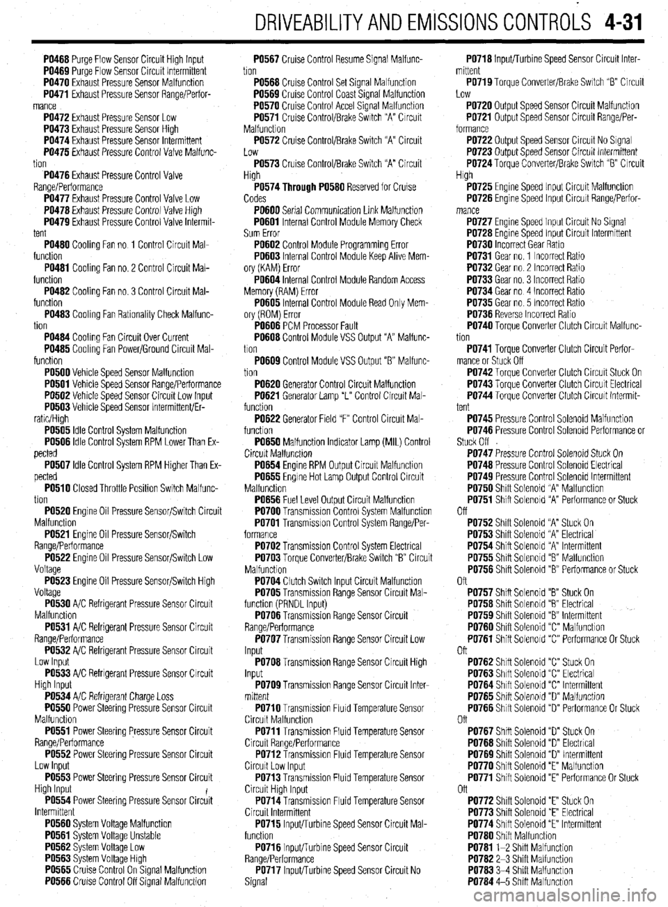
DRIVEABILITYAND EMISSIONSCONTROL-S 4-31
PO466 Purge Flow Sensor Circuit High Input
PO469 Purqe Flow Sensor Circuit Intermittent
PO470 Exhaust Pressure Sensor Malfunction
PO471 Exhaust Pressure Sensor Range/Perfor-
mance
PO472 Exhaust Pressure Sensor Low
PO473 Exhaust Pressure Sensor Hiah
PO474 Exhaust Pressure Sensor lnirmittent
PO475 Exhaust Pressure Control Valve Malfunc-
tion
PO476 Exhaust Pressure Control Valve
Range/Performance
PO477 Exhaust Pressure Control Valve Low
PO476 Exhaust Pressure Control Valve High
PO479 Exhaust Pressure Control Valve Intermit-
tent
PO460 Cooling Fan no 1 Control Circuit Mal-
function
PO461 Cooling Fan no. 2 Control Circuit Mal-
function
PO462 Cooling Fan no. 3 Control Circuit Mal-
function
PO463 Cooling Fan Rationality Check Malfunc-
tion
PO464 Cooling Fan Circuit Over Current
PO465 Cooling Fan Power/Ground Circuit Mal-
function
PO500 Vehicle Speed Sensor Malfunction
PO501 Vehicle Speed Sensor Range/Performance
PO502 Vehicle Speed Sensor Circuit Low Input
PO503 Vehicle Speed Sensor Intermittent/Er-
ratic/High
PO505 Idle Control System Malfunction
PO506 Idle Control System RPM Lower Than Ex-
pected
PO507 Idle Control System RPM Higher Than Ex-
pected
PO510 Closed Throttle Position Switch Malfunc-
tion
PO520 Engine Oil Pressure Sensor/Switch Circuit
Malfunction
PO521 Engine Oil Pressure Sensor/Switch
Range/Performance
PO522 Engine Oil Pressure Sensor/Switch Low
Voltage
PO523 Engine Oil Pressure Sensor/Switch High
Voltage
PO530 A/C Refrigerant Pressure Sensor Circuit
Malfunction
PO531 A/C Refrigerant Pressure Sensor Circuit
Range/Performance
PO532 A/C Refrigerant Pressure Sensor Circuit
Low Input
PO533 A/C Refrigerant Pressure Sensor Circuit
High Input
PO534 A/C Refrigerant Charge Loss
PO550 Power Steering Pressure Sensor Circuit
Malfunction
PO551 Power Steering Pressure Sensor Circuit
Range/Performance
PO552 Power Steering Pressure Sensor Circuit
Low Input
PO553 Power Steering Pressure Sensor Circuit
High Input
PO554 Power Steering Pressure Sensor Circiit
Intermittent
PO560 System Voltage Malfunction
PO561 System Voltage Unstable
PO562 System Voltage Low
PO563 Svstem Voltaoe Hlah
PO565 Ciuise Control On%ignal Malfunction
PO566 Cruise Control Off Signal Malfunction PO567 Cruise Control Resume Signal Malfunc-
tion
PO566 Cruise Control Set Signal Malfunction
PO569 Cruise Control Coast Signal Malfunction
PO570 Cruise Control Accel Signal Malfunction
PO571 Cruise Control/Brake Switch “A” Circuit
Malfunction
PO572 Cruise Control/Brake Switch “A” Circuit
Low
PO573 Cruise Control/Brake Switch “A” Circuit
High
P0574Through PO560 Reserved for Cruise
Codes
PO600 Serial Communication Link Malfunction
PO601 Internal Control Module Memory Check
Sum Error
PO602 Control Module Programming Error
PO603 Internal Control Module Keep Alive Mem-
ory (KAM) Error
PO604 Internal Control Module Random Access
Memory (RAM) Error
PO605 Internal Control Module Read Only Mem-
ory (ROM) Error
PO606 PCM Processor Fault
PO606 Control Module VSS Output “A” Malfunc-
tion
PO609 Control Module VSS Output “6” Malfunc-
tion
PO620 Generator Control Circuit Malfunction
PO621 Generator Lamp “L” Control Circuit Mal-
function
PO622 Generator Field “F” Control Circuit Mal-
function
PO650 Malfunction Indicator Lamp (MIL) Control
Circuit Malfunctron
PO654 Engine RPM Output Circuit Malfunction
PO655 Engine Hot Lamp Output Control Circuit
Malfunction
PO656 Fuel Level Output Circuit Malfunction
PO700 Transmission Control System Malfunction
PO701 Transmission Control System Range/Per-
formance
PO702 Transmission Control System Electrical
PO703 Torque Converter/Brake Switch “B” Circuit
Malfunction
PO704 Clutch Switch Input Circuit Malfunction
PO705 Transmission Range Sensor Circuit Mal-
function (PRNDL Input)
PO706 Transmission Range Sensor Circuit
Range/Performance
PO707 Transmission Range Sensor Circuit Low
Input
PO706 Transmission Range Sensor Circuit High
Input
PO709 Transmission Range Sensor Circuit Inter-
mittent
PO710 Transmission FluId Temperature Sensor
Circuit Malfunction
PO711 Transmission Fluid Temperature Sensor
Circuit Range/Performance
PO712 Transmission Fluid Temperature Sensor
Circuit Low Input
PO713 Transmission Fluid Temperature Sensor
Circuit High Input
PO714 Transmission Fluid Temperature Sensor
Circuit Intermittent
PO715 Input/Turbine Speed Sensor Circuit Mal-
function
PO716 Input/Turbine Speed Sensor Circuit
Range/Performance
PO717 InpWurbine Speed Sensor Circuit No
Signal PO716 Inputflurbine Speed Sensor Circuit Inter-
mittent
PO719 Torque Converter/Brake Switch “B” Circuit
Low
PO720 Output Speed Sensor Circuit Malfunction
PO721 Output Speed Sensor Circuit Range/Per-
formance
PO722 Output Speed Sensor Circuit No Signal
PO723 Output Speed Sensor Circuit Intermittent
PO724 Toraue Converter/Brake Switch “B” Circuit
High
PO725 Engine Speed Input Circuit Malfunction
PO726 Engine Speed Input Circuit Range/Perfor-
PO727 Engine Speed Input Circuit No Signal
PO726 Engine Speed Input Circuit Intermittent
PO730 Incorrect Gear Ratio
PO731 Gear no. 1 Incorrect Ratio
PO732 Gear no. 2 Incorrect Ratio
PO733 Gear no. 3 Incorrect Ratio
PO734 Gear no 4 Incorrect Ratio
PO735 Gear no. 5 Incorrect Ratio
PO736 Reverse Incorrect Ratio
PO740 Torque Converter Clutch Circuit Malfunc-
tion
PO741 Torque Converter Clutch Circuit Perfor-
mance or Stuck Off
PO742 Torque Converter Clutch Circuit Stuck On
PO743 Torque Converter Clutch Circuit Electrical
PO744 Torque Converter Clutch Circuit Intermit-
tent
PO745 Pressure Control Solenoid Malfunction
PO746 Pressure Control Solenoid Performance or
Stuck Off
PO747 Pressure Control Solenoid Stuck On
PO746 Pressure Control Solenoid Electrical
PO749 Pressure Control Solenoid Intermittent
PO750 Shift Solenoid “A” Malfunction
PO751 Shift Solenoid “A” Performance or Stuck
Off
PO752 Shift Solenoid “A” Stuck On
PO753 Shift Solenoid “A” Electrical
PO754 Shift Solenoid “A” Intermittent
PO755 Shift Solenoid “8 Malfunction
PO756 Shift Solenoid “B” Performance or Stuck
Oft
PO757 Shift Solenoid “B” Stuck On
PO756 Shift Solenoid “6” Electrical
PO759 Shift Solenoid “8” Intermittent
PO760 Shift Solenoid “C” Malfunction
PO761 Shift Solenoid “C” Performance Or Stuck
Oft
PO762 Shift Solenoid “C” Stuck On
PO763 Shift Solenoid “C” Electrical
PO764 Shift Solenoid “C” Intermittent
PO765 Shift Solenoid “D” Malfunction
PO766 Shift Solenoid “D” Performance Or Stuck
Oft
PO767 Shift Solenoid “D” Stuck On
PO766 Shift Solenoid “D” Electrical
PO769 Shift Solenoid “D” Intermittent
PO770 Shift Solenoid “E” Malfunction
PO771 Shift Solenoid “E” Performance Or Stuck
Off
PO772 Shift Solenoid “E” Stuck On
PO773 Shift Solenoid “E” Electrical
PO774 Shift Solenoid “E” Intermittent
PO760 Shift Malfunction
PO761 l-2 Shift Malfunction
PO762 2-3 Shift Malfunction
PO763 3-4 Shift Malfunction
PO764 4-5 Shift Malfunction
Page 197 of 408
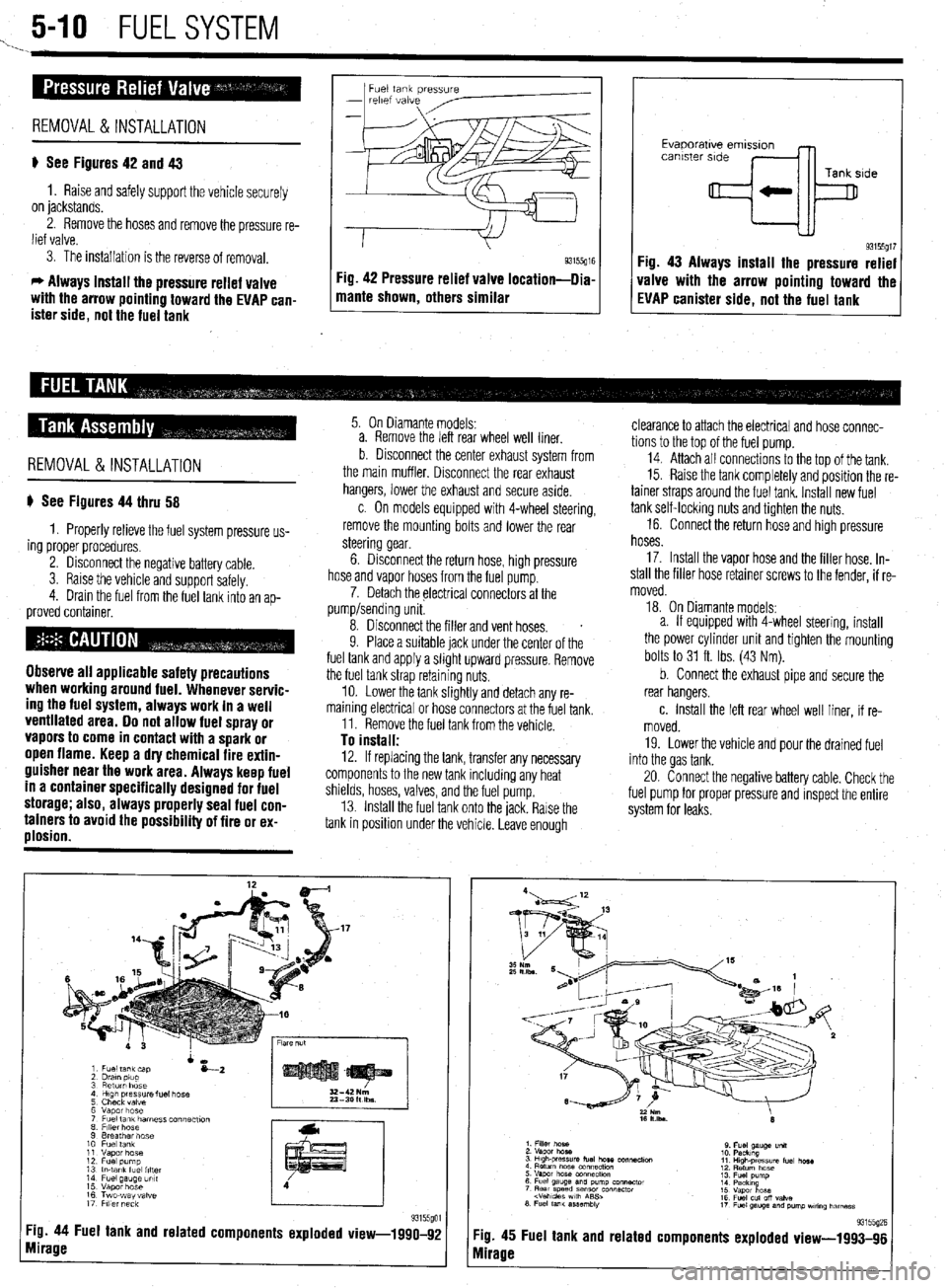
5-10 FUELSYSTEM
1. _
Fuel tank pressure
-
relef vdive
REMOVAL &INSTALLATION
p See Figures 42 and 43
1. Raise and safely support the vehicle securely
on jackstands.
2. Remove the hoses and remove the pressure re-
lief valve.
3. The installation is the reverse of removal.
c, Always install the pressure relief valve
with the arrow pointing toward the EVAP can-
ister side, not the fuel tank 1 mame shown, others similar g3155g” Fig 42 Pressure relief valve location-llia
I I
Evaporatwe emlsslon
canister side
Tank side
+k
93155gt7 Fig. 43 Always install the pressure relief
valve with the arrow pointing toward the
EVAP canister side, not the fuel tank
REMOVAL&INSTALLATION
p See Figures 44 thru 58
1. Properly relieve the fuel system pressure us-
ing proper procedures.
2. Disconnect the negative battery cable.
3. Raise the vehicle and support safelv.
4. Drain the fuel from the fuel tank into an
ap- proved container.
Observe all applicable safety precautions
when working around fuel. Whenever servic-
ing the fuel system, always work in a well
ventilated area. Do not allow fuel spray or
vapors to come in contact with a spark or
open flame. Keep a dry chemical fire extin-
guisher near the work area. Always keep fuel
in a container specifically designed for fuel
storage; also, always properly seal fuel con-
tainers to avoid the possibility of fire or ex-
plosion.
5. On Diamante models:
a. Remove the left rear wheel well liner.
b Disconnect the center exhaust system from
the main muffler. Disconnect the rear exhaust
hangers, lower the exhaust and secure aside.
c. On models equipped with 4-wheel steering,
remove the mounting bolts and lower the rear
steering gear.
6. Disconnect the return hose, high pressure
hose and vapor hoses from the fuel pump.
7. Detach the electrical connectors at the
pump/sending unit.
8. Disconnect the filler and vent hoses.
s
9. Place a suitable jack under the center of the
fuel tank and apply a slight upward pressure. Remove
the fuel tank strap retaining nuts.
10. Lower the tank slightly and detach any re-
maining electrical or hose connectors at the fuel tank.
11. Remove the fuel tank from the vehicle.
To install: 12. If replacing the tank, transfer any necessary
components to the new tank including any heat
shields, hoses, valves, and the fuel pump.
13. Install the fuel tank onto the jack. Rarse the
tank in position under the vehicle. Leave enough
Tg. 44 Fuel tank and related components exploded view-1990-92
mirage
clearance to attach the electrical and hose connec-
tions to the top of the fuel pump.
14. Attach all connectrons to the top of the tank.
15. Raise the tank completely and position the re-
tainer straps around the fuel tank. Install new fuel
tank self-locking nuts and tighten the nuts.
16. Connect the return hose and high pressure
hoses.
17. Install the vapor hose and the filler hose. In-
stall the filler hose retainer screws to the fender, if re-
moved.
18. On Diamante models:
a. If equipped with 4-wheel steering, install
the power cylinder unit and tighten the mounting
bolts to 31 ft. Ibs. (43 Nm).
b. Connect the exhaust pipe and secure the
rear hangers.
c. Install the left rear wheel well liner, if re-
moved.
19. Lower the vehicle and pour the drained fuel
into the gas tank.
20. Connect the negative battery cable. Check the
fuel pump for proper pressure and inspect the entire
system for leaks.
:ig. 45
vlirage Fuel tank and related 93155(12E components exploded view-1993-96
Page 213 of 408
640 CHASSIS ELECTRICAL
careful not to allow anything to come in contact with
the air bag unit.
16. Remove the glove box lamp assembly.
17. Remove the remaining instrument panel
mounting screws and remove the instrument panel
from the vehicle.
18. Remove the left side foot shower ductwork,
lap cooler duct and center duct.
19. Remove the front and center reinforcements
and center stay assembly.
20. Remove the air distribution duct assembly.
21. Detach all connectors from heater-box-
mounted items.
22. Remove the heater box mounting screws and
nut, then remove the unit from the vehicle.
23. Disassemble on a workbench. Remove the
heater core from the heater case.
To install:
24. Thoroughly clean and dry the inside of the
case and install the heater core and all related parts.
25. Install the heater unit to the vehicle and install
the mounting screws and nut. Be sure the evaporator
case and heater case are fitted together properly. At-
tach all connectors to heater-box-mounted items.
26. Install the air distribution duct assembly. In-
stall the front and center reinforcements and center
stay assembly.
27. Install the center duct, lap cooler duct and left
side foot shower duct.
28. Install the instrument panel and mounting
screws.
29. Install the glove box lamp assembly.
30. Secure the steering column and attach all
steering column connectors.
31. Install the speedometer cable adapter to the
instrument panel.
32. Install the instrument cluster and the instru-
ment cluster bezel.
33. Install the speakers to the top of the instru-
ment panel.
34. Install the cup holder.
35. Install the climate control system control
head.
36. Install the stereo entertainment system and
bezel.
37. Install the screw below the glove box assem-
bly, and the entire glove box unit.
38. Install the steering column covers.
39. Install the knee protector support bracket, the
protector and the decorative plugs.
40. Install the console and the ashtray. 41. Install the right side foot shower duct.
42. Install the passenger side undercover.
43. Connect the heater hoses to the core tubes.
44. Fill the cooling system.
45. Connect the negative battery cable and check
the entire climate control system for proper operation
and leaks.
Galant
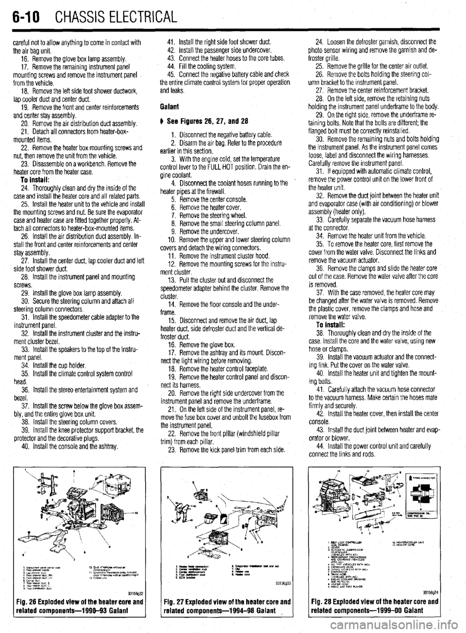
# See Figures 26, 27, and 28
1. Disconnect the negative battery cable.
2. Disarm the air bag. Refer to the procedure
earlier in this section.
3. With the engine cold, set the temperature
control lever to the FULL HOT position. Drain the en-
gine coolant.
4. Disconnect the coolant hoses running to the
heater pipes at the firewall.
5. Remove the center console.
6. Remove the heater cover.
7. Remove the steering wheel.
8. Remove the small steering column panel.
9. Remove the undercover.
10. Remove the upper and lower steering column
covers and detach the wiring connectors.
11. Remove the instrument cluster hood.
12. Remove the mounting screws for the instru-
ment cluster.
13. Pull the cluster out and disconnect the
speedometer adapter behind the cluster. Remove the
cluster.
14. Remove the floor console and the under-
frame.
15. Disconnect and remove the air duct, lap
heater duct, side defroster duct and the vertical de-
froster duct.
16. Remove the glove box.
17. Remove the ashtray and its mount. Discon-
nect the light wiring before removing.
18. Remove the heater control faceplate.
19. Remove the heater control panel and discon-
nect its harness.
20. Remove the right side undercover from the
instrument panel and remove the underframe.
21. On the left side of the instrument panel, re-
move the fuse box cover and unbolt the fusebox from
the instrument panel.
22. Remove the front pillar (windshield pillar
trim) from each pillar.
23. Remove the kick panel trim from each side.
Fig. 26 Exploded view of the heater core and
related components-1990-93 Galant
:IQ. 27 Exploded view of the heater core and
-elated components-1994-98 Galant 24. Loosen the defroster garnish, disconnect the
photo sensor wiring and remove the garnish and de-
froster grille.
25. Remove the grille for the center air outlet.
26. Remove the bolts holding the steering col-
umn bracket to the instrument panel.
27, Remove the center reinforcement bracket.
28. On the left side, remove the retaining nuts
holding the instrument panel underframe to the body.
29. On the right side, remove the underframe re-
taining bolts. Note that the bolts are different; the
flanged bolt must be correctly reinstalled.
30. Remove the remaining nuts and bolts holding
the instrument panel. As the instrument panel comes
loose, label and disconnect the wiring harnesses.
Carefully remove the instrument panel.
31. If equipped with automatic climate control,
remove the power control unit on the lower front of
the heater unit.
32. Remove the duct joint between the heater unit
and evaporator case (with air conditioning) or blower
assembly (heater only).
33. Carefully separate the vacuum hose harness
at the connector.
34. Remove the heater unit from the vehicle.
35. To remove the heater core, first remove the
cover from the water valve. Disconnect the links and
remove the vacuum actuator.
36. Remove the clamps and slide the heater core
out of the case. Remove the water valve after the core
is removed.
37. With the case removed, the heater core may
be changed after the water valve is removed. Remove
the plastic cover, remove the clamps and hose and
remove the water valve.
To install:
38. Thoroughly clean and dry the inside of the
case. Install the core and the water valve, using new
hose or clamps.
39. Install the vacuum actuator and the connect-
ing link. Put the cover on the water valve.
40. Install the heater unit and tighten the mount-
ing bolts.
41. Carefully attach the vacuum hose connector
to the vacuum harness. Make certain the hoses mate
firmly and securely.
42. Install the heater cover, then install the center
console.
43. Install the duct joint between heater and evap-
orator or blower.
44. Install the power control unit and carefully
connect the links and rods.
Fig. 28 Exploded view of the heater core and
related components-1999-00 Galant