1900 MITSUBISHI DIAMANTE Power steering
[x] Cancel search: Power steeringPage 233 of 408
6-30 CHASSIS ELECTRICAL
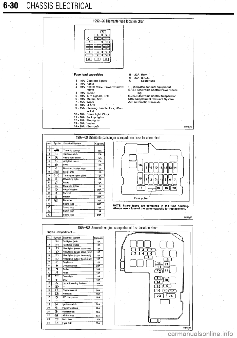
1992-96 Diamante fuse location chart
I
Fuse load caaacities 15 -2OA Horn
16 - 20A (E.C.S.)
1 - 15A Cigarette lighter 17 - spare fuse
2 - 10A Radio
3 - 10A Heater relay, (Power window ( ) indicates optlonal equipment
relay) E P.S.: Electronic Control Power Steer-
4 - 10A (E.P.S) ing
5 - 10A Turn signals, SRS E.C.S.: Electronic Control Suspension
6 - 10A Meters, SRS SRS~ Supplement Restratnt System
7 - 15A Wiper A/T: Automatic Transaxle
8-10A (4AIT)
9- 15A Steering handle lock, (Door
locks)
lo- 10A Dome light, Clock
11 - 10A Backup lights
12 -2OA StoplIghts
13 -3OA Heater
14 - 20A (Sunroof)
93156fllE
1997-00 Diamante passenger compartment fuse location chart No Symbol Electrical System
I capactty
I
Spare fuses are contained in the fuse housing
use a fuse of the same capacity for replacement.
199740 Diamante encline
compartment fuse location chart
Page 281 of 408
7-2 'DRIVETRAIN
Because of the way an internal combustron engine
breathes, it can produce torque, or twisting force,
only within a narrow speed range. Most modern,
overhead valve pushrod engines must turn at about
2500 rpm to produce their peak torque By 4500 rpm
they are producrng so lrttle torque that contrnued in-
creases in engine speed produce no power increases.
The torque peak on overhead camshaft engines IS
generally much higher, but much narrower.
The manual transaxle and clutch are employed to
vary the relationship between engine speed and the
speed of the wheels so that adequate engine power can
be produced under all crrcumstances. The clutch al-
lows engine torque to be applied to the transaxle input
shaft gradually, due to mechanical slippage. Conse-
quently, the vehicle may be started smoothly from a
full stop The transaxle changes the ratio between the
rotating speeds of the engine and the wheels by the
use of gears. The gear ratios allow full engine power to
be applied to the wheels during acceleration at low
speeds and at highway/passing speeds.
In a front wheel drive transaxle, power is usually
transmitted from the input shaft to a mainshaft or out-
put shaft located slightly beneath and to the side of
the input shaft. The gears of the mainshaft mesh with
gears on the input shaft, allowing power to be carried
from one to the other. All forward gears are in con-
stant mesh and are free from rotating with the shaft
unless the synchronizer and clutch IS engaged. Shaft-
ing from one gear to the next causes one of the gears
to be freed from rotating with the shaft and locks an-
other to it. Gears are locked and unlocked by internal
dog clutches which slide between the center of the
gear and the shaft. The forward gears employ syn-
chronizers; friction members which smoothly bring
gear and shaft to the same speed before the toothed
dog clutches are engaged.
SHIFT LINKAGE
1. Disconnect the shift linkage from the transaxle.
2. On the transaxle, put select lever in N and
move the shift lever in
4th gear. Depress the clutch,
if necessary, to shift.
3. Move the shift lever in the vehicle to the
4th gear position until it contacts the stop.
4. Turn the adjuster turnbuckle so the shift cable
eye aligns with the eye in the gear shift lever. When
installing the cable eye, make sure the flange side of
the plastic bushing at the shift cable end is on the
cotter pin side.
5 The cables should be adjusted so the clear-
ance between the shift lever and the 2 stoppers are
equal when the shift lever IS moved to 3rd and 4th
gear. Move the shift lever to each positron and check i
that the shifting is smooth
REMOVAL &INSTALLATION
1, Disconnect the negative battery cable 2. Remove any components necessary to access
the back-up light switch.
3. Unplug the back-up light switch connector.
4. Remove the switch from the case using the ap-
propriate size socket and drive tool.
To install: 5. Install the switch and tighten it to 22-25 ft. Ibs.
(30-35 Nm).
6. Attach the back-up light switch connector
7. Install any components removed to access the
back-up light switch
8. Connect the negative battery cable.
REMOVAL & INSTALLATION
Mirage
*If the vehicle is going to be roiled while the
halfshafts are out of the vehicle, obtain 2 outer
CV-joints or proper equivalent tools and install
to the hubs. If the vehicle is rolled without the
proper torque applied to the front wheel bear-
ings, the bearings will no longer be usable.
*The suspension components should not be
tightened until the vehicles weight is resting
on the ground.
1. Remove the battery and battery tray.
2. Remove the air cleaner assembly and vacuum
hoses.
3. Note the locations and disconnect the shifter
cables.
4. If equipped with 1.61 engine, remove the ten-
sion rod.
5. Detach the backup lamp switch connector,
speedometer cable connection and remove the starter
motor.
6. Raise the vehicle and support safely.
7. Remove the front wheels and the inner wheel
panels.
8. Remove the undercover and splash pan.
9. Drain the transaxle oil into a suitable con-
tainer
10. Support the engine and remove the cross-
member.
11. Remove the upper transaxle mounting bolt
and bracket.
12 Disconnect the stabilizer bar, tie rod ends and
the lower ball joint connections.
13 Remove the clutch release cylinder and clutch
oil line bracket. Do not disconnect the fluid lines and
secure the slave cylinder with wire.
14 Disconnect the clutch cable, if equipped with
cable controlled clutch system.
15. Remove the halfshafts by inserting a prybar
between the transaxle case and the driveshaft and
prying the shaft from the transaxle. Do not pull on the
driveshaft Doing so damages the inboard joint. Do
not insert the prybar so far the oil seal in the case is
damaged.
*It is not necessary to disconnect the half-
shafts from the steering knuckle. Remove the
shaft with the hub and knuckle as an assem-
bly. Tie the shafts aside. Note the circle clip
on the end of the inboard shafts should not
be reused.
16. Remove the bellhousing lower cover.
17 Remove the transaxle to engine bolts and
lower the transaxle from the vehrcle.
To install:
*When installing the transaxle, be sure to
align the splines of the transaxle with the
clutch disc.
18 Install the transaxle to the engine and install
the mounting bolts. Tighten the bolts to 31-40 ft. Ibs.
(43-55 Nm) on 1990-92 models and 35 ft. Ibs. (48
Nm) on 1993-00 models.
19 Install the bellhousing cover.
*When installing the halfshafts, use new
circlips on the axle ends. Care must be taken
to ensure that the oil seal lip of the transaxle
is not damaged by the serrated part of the
driveshaft.
20. Install and fully seat the halfshafts into the
transaxle.
21. Install the slave cylinder.
22. Connect the ball joints, tie rod ends and the
stabilizer bar connections.
23. Install the upper transaxle mounting bracket
and bolt.
24. Install the crossmember.
25. Install the undercover.
26. Install the upper transaxle-to-engine mount-
ing bolts, Tighten the bolts to 31-40 ft. Ibs. (43-55
Nm) on 199C-92 models and 35 ff. Ibs. (48 Nm) on
1993-00 models.
27. Install the starter motor.
28 Connect the backup light switch connector
and speedometer cable.
29 Connect and adjust the shifter cables.
30 Install the air cleaner assembly.
31. Install the front wheels.
32 Make sure the vehicle is level when refilling
the transaxle Use Hypoid gear oil or equivalent, GL-
4 or higher.
33. Connect the negative battery cable and check
the transaxle for proper operation. Make sure the re-
verse lights operate when in reverse.
Galant
1999-93 MODELS
rlf the vehicle is going to be rolled on its
wheels while the halfshafts are out of the ve-
hicle, obtain two outer CV-joints or proper
equivalent tools and install to the hubs. If the
vehicle is rolled without the proper torque
applied to the front wheel bearings, the bear-
ings will no longer be usable.
1. Remove the battery and the air intake hoses.
2. If equipped with Active-ECS, unplug the
compressor wiring.
3. Remove the auto-cruise actuator and under-
hood bracket, located on the passenger side inner
fender well.
4. Drain the transaxle and transfer case fluid, if
equipped, into a suitable waste container.
5. Remove the retainer bolt and pull the
speedometer cable from the transaxle assembly.
6. Remove the cotter pin securing the select and
shift cables and remove the cable ends from the
transaxle.
Page 289 of 408
7-10 DRIVETRAIN
The automatic transaxle allows engine torque and
power to be transmitted to the front wheels within a
narrow range of engine operating speeds. It will allow
the engine to turn fast enough to produce plenty of
power and torque at very low speeds, while keeping it
at a sensible rpm at high vehicle speeds (and it does
this job without driver assistance). The transaxle uses
a light fluid as the medium for the transmission of
power. This fluid also works in ths operation of vari-
ous hydraulic control circuits and as a lubricant. Be-
cause the transaxle fluid performs all of these func-
tions, trouble within the unit can easily travel from one
part to another For this reason, and because of the
complexity and unusual operating principles of the
transaxle, a very sound understanding of the basic
principles of operation will simplify troubleshooting
REMOVAL &INSTALLATION
Pan removal, fluid and filter
in Section 1 of this manual changes are covered
REMOVAL &INSTALLATION
1990-97 Mirage and 1990-93 Galant
# See Figure 44
1. Disconnect the negative battery cable.
2. Disconnect the selector cable from the lever
3. Remove the two retaining screws and lift off
the switch.
To install: 4. Mount and position new switch. Do not tighten
the bolts until the switch is adjusted.
5. Connect selector cable and adjust switch.
6. After installation and adjustment make sure the
engine only starts in the
P and N selections. Also check
that the reverse lights operate only in the R selectlon.
1994-00 Galant and 1998-00 Mirage
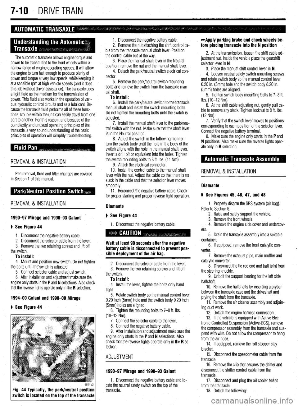
e See Figure 44
93157pm Fig. 44 Typically, the park/neutral position
switch is located on the top of the transaxle
1. Disconnect the negative battery cable.
2. Remove the nut attaching the shift control ca-
ble from the transaxle manual shaft lever. Position
the control cable out of the way.
3. Place the manual shaft lever in the Neutral
position, remove the nut and the manual shaft lever.
4. Detach the park/neutral switch electrical con-
nector.
5. Remove the park/neutral switch mounting
bolts and remove the switch from the transaxle man-
ual shaft.
To install: 6. Install the park/neutral switch to the transaxle
manual shaft and install the switch mounting bolts
Do not tighten the mounting bolts unh the switch is
adjusted.
7. Install the manual shaft lever to the park/neu-
tral switch with the nut. Make sure that the shaft lever
is in the Neutral position.
8. Adjust the switch in the following manner:
turn the switch body until the hole in the body of the
switch aligns with the hole in the manual shaft lever.
Insert a drill bit or equivalent into the holes. Tighten
the switch mounting bolts to 8 ft. Ibs. (11 Nm).
9. Attach the electrical connector.
10. Install the control cable to the manual shaft
lever with the nut. Adjust the cable so that there is no
slack in the cable and that the selector lever moves
smoothly
11. Reconnect the negative battery cable Check
for proper starting and proper reverse light operatron.
Diamante
ti See Figure 44
1. Disconnect the negative battery cable.
Wait at least 90 seconds after the negative
battery cable is disconnected to prevent pos-
sible deployment of the air bag.
2. Disconnect the selector cable from the lever.
3. Remove the two retaining screws and lift off
the switch.
To install: 4. Install the lever, tighten the bolts only hand
tight.
5. Rotate switch body so the manual control lever
0.20 inch (5mm) hole and the switch body 0.20 inch
(5mm) holes are aligned.
6. Tighten the mounting bolts to 7-8 ft. Ibs.
(10-12 Nm).
7. Connect the selector cable to the lever.
8. Connect the negative battery cable.
9. After installahon and adjustment make sure the
engine only starts in the
P and N selections. Also
check that the reverse lights operate only in the R se- lection.
ADJUSTMENT
1990-97 Mirage and 1990-93 Galant
1. Disconnect the negative battery cable and lo-
cate the neutral safety switch on the top of the
transaxle.
*Apply parking brake and chock wheels be-
fore placing transaxle into the N position
2. At the transmission, loosen the shift cable ad-
justment nut. Inside the vehicle place the gearshift
selector lever in N
3. Place the manual shift control lever in N.
4. Loosen neutral safety switch mounhng screws
and rotate switch body so the manual control lever
0.20 in. (5mm) hole and the switch body 0.20 in.
(5mm) holes are aligned.
5. Tighten switch body mounting bolts to 7-8 ft.
Ibs. (lo-12 Nm).
6. At the shift cable adjusting nut, gently pull ca-
ble to remove any slack. Tighten locknut to 8 ft. Ibs.
(12 Nm)
7. Verify that the switch lever moves to positions
corresponding to each position of the selector lever.
Connect the negative battery terminal.
8. Make sure the engine only starts in the
P and
N positions. Also make sure the reverse lights oper-
ate only in
R selection.
REMOVAL&INSTALLATION
Diamante
) See Figures 45, 46, 47, and 48
1. Properly disarm the SRS system (air bag).
Refer to Section 6.
2. Raise and safely support the vehicle.
3. Remove the front wheels.
4. Remove the engine side cover and undercov-
ers.
5. Drain the transaxle assembly into a suitable
container.
6. If equipped, remove the front catalytic con-
verter.
7. Remove the exhaust pipe, main muffler and
catalytic converter.
8. Disconnect the tie rod end and ball joint from
the steering knuckle.
9. Unbolt the support bearing for the left side
halfshaft.
10. Remove the halfshafts by inserting a prybar
between the transaxle case and the driveshaft and
prying the shaft from the transaxle.
11. Remove the air cleaner assembly and adjoin-
ing duct work.
12. Detach the engine harness connection.
13. If the vehicle is equipped with Active Elec-
tronlc Controlled Suspension (Active-ECS), remove
the compressor assembly from the transaxle and sus-
pend with wire. Do not allow the compressor to hang
from the air hose.
14. If equipped, remove the roll stopper stay
bracket.
15. Disconnect the speedometer cable from the
transaxle.
16. Remove the clip that secures the shifter and
disconnect the shifter control cable from the
transaxle.
17. Disconnect and plug the oil cooler hoses
from the transaxle.
18. Detach the following:
Page 296 of 408
WHEELS 8-2
WHEEL ASSEMBLY 8-2
REMOVAL & INSTALLATION 8-2
INSPECTION 8-2
WHEELLUG STUDS 8-2
REMOVAL & INSTALLATION 8-2
FRONT SUSPENSION 8-4
MACPHERSONSTRUTAND COIL
SPRING 8-7
REMOVAL & INSTALLATION 8-7
OVERHAUL 8-7
SHOCKABSORBERAND COIL
SPRING 8-8
REMOVAL &INSTALLATION 8-8
OVERHAUL 8-9
UPPER BALLJOINT 8-9
REMOVAL & INSTALLATION 8-9
INSPECTION 8-9
UPPER CONTROLARM 8-10
REMOVAL &INSTALLATION 8-10
LOWER BALLJOINT 8-10
REMOVAL &INSTALLATION 8-10
INSPECTION 8-10
LOWER CONTROL ARM 8-10
REMOVAL&INSTALLATION 8-10
SWAY BAR 8-12
REMOVAL & INSTALLATION 8-12
KNUCKLE, HUB, AND BEARING 8-13
REMOVAL & INSTALLATION 8-13
WHEEL ALIGNMENT 8-16
CASTER 8-16
CAMBER 8-17
TOE 8-17
REAR SUSPENSION 8-18
STRUT AND COIL SPRING 8-21
REMOVAL & INSTALLATION 8-21
OVERHAUL 8-22
UPPER CONTROLARMS 8-22
REMOVAL & INSTALLATION 8-22
LOWER CONTROL ARMS 8-23
REMOVAL &INSTALLATION 8-23
TRAINING ARM 8-24
REMOVAL & INSTALLATION 8-24
SWAY BAR 8-25
REMOVAL &INSTALLATION 8-25
HUB & BEARINGS 8-25
ADJUSTMENT 8-25
REMOVAL & INSTALLATION 8-25
STEERING 8-27
STEERING WHEEL 8-27
REMOVAL &INSTALLATION 8-27
COMBINATION SWITCH 8-29
REMOVAL &INSTALLATION 8-29
WINDSHIELD WIPER SWITCH 8-29
REMOVAL&INSTALLATION 8-29
IGNITION LOCK CYLINDER 8-29 '
REMOVAL &INSTALLATION 8-29
IGNITION SWITCH 8-30
REMOVAL &INSTALLATION 8-30
STEERING LINKAGE 8-30
REMOVAL&INSTALLATION 8-30
MANUAL RACK AND PINION STEERING
GEAR 8-31 REMOVAL & INSTALLATION 8-31
POWER RACK AND PINION STEERING
GEAR 8-32
REMOVAL &INSTALLATION 8-32
POWERSTEERING PUMP 8-34
REMOVAL &INSTALLATION 8-34
SYSTEM BLEEDING 8-36
COMPONENT LOCATIONS
FRONTSUSPENSION COMPONENT
LOCATIONS 8-4
REARSUSPENSION COMPONENT
LOCATIONS 8-18
SPECIFICATIONS CHARTS ’
TORQUE SPECIFICATIONS 8-39
Page 326 of 408
8-30 SUSPENSION AND STEERING
position. Remove the key from the ignition lock
cylinder.
b. Disconnect the negative battery cable and
insulate the cable end with high-quality electrical
tape or similar non-conductive wrapping.
c. Wait at least 1 minute before working on
the vehicle. The air bag system is designed to re-
tain enough voltage to deploy the air bag for a
short period of time even after the battery has
been disconnected.
3. Remove the steering wheel. as outlined ear-
lier in this section.
4. Remove the hood lock release handle.
5. Remove the switches from the knee protector
below the steering column, and remove the exposed
retaining screws. Then remove the knee protector.
6. Remove the column covers.
7. Remove necessary duct work and detach the
windshield wiper switch connectors. +
8. Remove the retaining screws and remove the
windshield wiper switch assembly from the steering
column.
To install: 9. Install the wiper switch to the steering col-
umn and connect the connectors.
IO. Install any removed duct work.
11. Install the column covers.
12. Install the knee protector and switches.
13. Install the hood release handle.
14. Confirm that the front wheels are in a straight
ahead position. Install the steering wheel, as outlined
earlier in this section.
15. Connect the negative battery cable and check
the windshield wiper and washer for proper opera-
tion
REMOVAL &INSTALLATION
The air bag system (SRS or SIR) must be dis-
armed before removing the steering wheel.
Failure to do so may cause accidental de-
ployment, property damage or personal in-
jury.
1. If equipped, properly disarm the air bag sys-
tern:
2. Disconnect the negative battery cable.
3. Remove the hood lock release lever from the
lower panel.
4. Remove the lower instrument panel knee pro-
tector.
5. Remove the ductwork with the lower knee
panel and remove the steering wheel assembly.
Use proper steering wheel puller equipment
when removing the steering wheel. The use
of a hammer for removal could damage the
collapsible mechanism within the column.
6. Remove the lower and upper steering column
covers.
7. For Diamante models, remove the lap cooler
and foot shower duct work.
8. If necessary, remove the clip that holds the
wiring harness against the steering column. 9. Detach all necessary connectors.
10. For Galant and Diamante models, remove the
retaining screws, then remove the entire column
switch/clockspring assembly from the left side of the
steering column.
11. For Diarnante models, remove the mounting
screws from the ignition switch and pull the switch
from the interlock cylinder.
12. Insert the key into the steering lock cylinder
and turn to the
ACC position.
13. With a small, pointed tool, push the lock pin
of the steering lock cylinder inward and pull the lock
cylinder out.
14. Remove the key reminder switch, if equipped.
To install: 15. For Mirage, install the lock cylinder in the
lock cylinder bracket. Make sure the cylinder oper-
ates properly before breaking off the heads of the
special bolts, if the bracket was replaced.
16. For Galant and Diarnante models, install the
lock cylinder into the interlock housing. Be sure the
lock pin snaps into place. Install the ignition switch
into the interlock housing. Align the keyway of the ig-
nition switch with the lock cylinder and secure with
the mounting screws.
17. For Galant and Diamante models, install the
column switch/clockspring assembly to the and con-
nect the harness.
18. install the key reminder switch, if equipped.
19. Attach the harness connections and install
the wiring clip.
20. If removed, install the lap cooler and foot
shower duct work.
21. Install the steering column upper and lower
covers.
22. If necessary, install the knee protector and the
steering wheel.
23. Install the hood lock release lever.
24. Connect the negative battery cable, enable the
air bag system, and check the ignition switch and
lock for proper operation.
REMOVALANDINSTALLATION
Mirage and Galant
I. Disconnect the negative battery cable. If
equipped, disarm the air bag system.
2. Remove the hood lock release lever from the
lower panel.
3. Remove the lower instrument panel knee pro-
tector.
4. Remove the ductwork with the lower knee
panel and remove the steering wheel assembly.
*Use proper steering wheel puller equip-
ment when removing the steering wheel. The
use of a hammer for removal could damage
the collapsible mechanism within the col-
umn.
5. Remove the lower steering column cover.
6. Remove the upper steering column cover.
7. Remove the clip that holds the wiring harness
against the steering column.
8. For Galant models, insert the key into the
steering lock cylinder and turn to the ACC position.
9. For Galant models, using a small pointed
tool, push the lock pin of the steering lock cylinder
inward and pull the lock cylinder out. IO. For Galant models, remove the key reminder
switch, if equipped.
11. Unplug the ignition switch harness connec-
tor. Remove the ignition switch mounting screws and
pull the switch from the steering lock cylinder.
*Vehicles equipped with automatic
transaxle have safety-lock systems and will
have a key interlock cable installed in a slide
lever on the side of the key cyfinder. Care-
fully unhook the interlock cable from the lock
cylinder while withdrawing the cylinder from
the lock housing.
To install:
*To remove the steerlng lock, use a hack-
saw or equivalent to cut the special bolts
through the bracket. The bracket and bolts
must be replaced with new ones.
12. With the ignition key removed, install the
slide lever and the interlock cable to the steering lock
cylinder. Apply grease to the interlock cable and in-
stall the cylinder into the lock housing. Check for
normal operation of the interlock system.
13. Install the ignition switch into the rear of the
lock cylinder housing. Be sure to align the keyway of
the ignition switch with interlock cylinder.
14. Attach the harness connections and install
the wiring clip.
15. Install the steering column upper and lower
covers.
16. Install the knee protector.
17. Connect the negative battery cable, enable the
air
bag system (if equipped) and check the ignition
switch and lock for proper operation.
Diamante
Work MUST NOT be started until at least 90
seconds after the ignition switch is turned to
the LOCK position and the negative battery
cable is disconnected from the battery. This
will allow time for the air bag system backup
power supply to deplete its stored energy
preventing accidental air bag deployment
which could result in unnecessary air bag
system repairs and/or personal injury.
I. Disconnect the negative battery cable.
2. Disarm the air bag system, as outlined in
Section 6.
3. Remove the steering wheel, as outlined ear-
lier in this section.
4. Remove the hood lock release handle.
5. Remove the switches from the knee protector
below the steering column and remove the exposed
retaining screws. Then remove the knee protector.
6. Remove the steering column upper and lower
covers. Use care removing the covers to prevent
breakage of alignment tabs.
7. Remove lap cooler and foot shower
duct work. Detach the ignition switch harness connectors.
8. Remove mounting screws from the ignition
switch and pull switch from interlock cylinder.
To install: 9. Install ignition switch into interlock housing.
Align keyway of ignition switch with lock cylinder and
secure with mounting screws.
IO. Connect the ignition switch electrical harness
Plug.
Page 329 of 408
SUSPENSION AND STEERING 8-33
*Matchmark the pinion input shaft of the
rack to the lower steering column joint for in-
stallation purposes.
6. Remove the pinch bolt holding the lower
steering column joint to the rack and pinion input
shaft.
7. Remove the cotter pins and disconnect the tie
rod ends from the steering knuckle.
8. Remove the rack and pinion steering assem-
bly and its rubber mounts from the right side of the
vehicle.
To install: 9. Align the matchmarks of the input shaft and
install the rack to the vehicle.
10. Secure the rack using the retainer clamps and
bolts. Tighten the bolts to 51 ft. Ibs. (70 Nm).
11. Tighten the steering column pinch bolt to 13
ft. Ibs. (18 Nm).
12. Install the center member.
13. Install the front exhaust pipe.
14. Connect the HO$ sensor.
15. Connect the tie rod ends to the steering
knuckles and tighten the castle nuts to 25 ft. Ibs. (34
Nm). Install new cotter pins.
16. Install the wheels and connect the negative
battery cable.
17. Have a front end alignment performed.
REMOVAL &INSTALLATION
Diamante
FRONT
*Prior to removal of the steering gear box,
center the front wheels and remove the igni-
tion key. Failure to do so may damage the
SRS clock spring and render SRS system in-
operative.
1. Disconnect the negative battery cable.
2. Disconnect the front exhaust pipe.
3. If equipped with AWD, remove the transfer
case assembly.
4. Remove the bolt holding the lower steering
column joint to the rack and pinion input shaft.
5. Remove the cotter pins and disconnect the tie
rod ends.
6. Remove the left and right frame members.
7. Remove the stabilizer bar bracket.
8. If equipped with four-wheel steering, discon-
nect the lines going to the rear pump.
9. Remove the rack and pinion steering assem-
bly and its rubber mounts. Move the rack to the right
to remove it from the crossmember.
To install: IO. Install the rack and mounting bolts. Tighten
the bolts to 51 ft. Ibs. (70 Nm). When installing the
rubber rack mounts, align the projection of the
mounting rubber with the indentation in the cross:
member. Install the pinch bolt.
11. Connect the pressure and return lines to the
rack and to the rear pump, if equipped.
12. Install the frame members and tighten the
bolts to 43-51 ft. Ibs. (60-70 Nm).
13. Connect the tie rods and install new cotter
pins. 14. Install the transfer case and front exhaust
pipe.
15. Refill the reservoir and bleed the system.
16. Have a front end alignment performed.
REAR
1. Disconnect the negative battery cable.
2. Raise the vehicle and support safely.
3. Drain the power steering fluid.
4. Remove the main muffler assembly.
5. Remove the rear shock absorber lower
mounting bolts.
6. Using the proper equipment, support the
weight of the rear differential. Remove the 2 small
crossmember brackets.
7. Remove the large self-locking crossmember
mounting nuts on the differential side.
8. Remove the oil line clamp bolts.
9. Remove the pressure tubes.
IO. Hold the tie rod ends stationary and remove
the tie rod end nuts. Remove the tie rod ends from
the trailing arms.
11. Remove the mounting bolts and remove the
rear steering gear.
To install: 12. Secure the unit to the crossmember. Move
the power cylinder piston rod over its full stroke to
determine its neutral position.
13. Align the tie rod ends with the holes in the
trailing arms and install the nuts. Adjust the length of
the tie rods with the nuts if necessary. The difference
in length between the 2 tie rod ends should not ex-
ceed 0.04 in. (1 mm). The nuts’ torque specification is
42 ft. Ibs. (58 Nm).
14. Replace the O-rings and install the pressure
tubes. Clamp in place.
15. Install the large self-locking crossmember
mounting nuts on the differential side. Tighten to
80-94 ft. Ibs. (110-130 Nm).
16. Remove the support equipment.
17. Install the 2 small crossmember brackets.
18. Install the shock mounting bolts.
19. Install the muffler assembly.
20. Refill the reservoir and bleed the system.
21. Have a front end alignment performed. _
Galant
1990-93 MODELS
1. Disconnect the negative battery cable.
2. Drain the power steering fluid.
3. Raise the vehicle and support safely.
4. Remove the bolt holding lower steering col-
umn joint to the rack and pinion input shaft.
5. Remove the transfer case, if equipped.
6. Remove the cotter pins and using the proper
tools, separate the tie rod ends from the steering
knuckle.
7. Locate the triangular brace near the stabilizer
bar brackets on the crossmember and remove both
the brace and the stabilizer bar bracket.
8. Support the center crossmember.
9. Remove the through-bolt from the round roll
stopper and remove the rear bolts from the center
crossmember.
10. Disconnect the front exhaust pipe, if
equipped with FWD.
11. Disconnect the power steering fluid pressure
pipe and return hose from the rack fittings. Plug the
fittings to prevent excess fluid leakage. 12. Lower the crossmember slightly.
13. Remove the rack and pinion steering assem-
bly and its rubber mounts. Move the rack to the right
to remove from the crossmember. Tilt the assembly
downward and remove from the left side of the vehi-
cle. Use caution to avoid damaging the boots.
To install: 14. Install the rack and install the mounting bolts. Tighten the mounting bolts to 43-58 ft. Ibs. (60-80
Nm). When installing the rubber rack mounts, align
the projection of the mounting rubber with the inden-
tation in the crossmember.
15. Connect the power steering fluid lines to the
rack.
16. Connect the exhaust pipe, if removed.
17. Raise the crossmember into position. Install
the center member mounting bolts and tighten to 72
ft. Ibs. (100 Nm). Install the roll stopper bolt and new
nut. Tighten nut to 47 ft. Ibs. (65 Nm).
18. Install the stabilizer bar brackets and brace.
19. Connect the tie rod ends and tighten nuts to
25 ft. Ibs. (34 Nm).
20. Install the transfer case, if removed. Check
and fill fluid.
21. Refill the reservoir with power steering fluid
and bleed the system.
22. Have a front end alignment performed.
1994-M MODELS
+ See Figure 96
Prior to removal of the steering gear box,
center the front wheels and remove the igni-
tion key. Failure to do so may damage the
SRS clock spring and render SRS system in-
operative.
1. Disconnect the negative battery cable.
2. Raise and properly support the vehicle.
3. Remove both front wheel assemblies.
4. Remove the bolt holding lower steering col-
umn joint to the rack and pinion input shaft.
5. Remove the stabilizer bar.
6. Remove the cotter pins, and using joint sepa-
rator MB991 113 or equivalent, disconnect the tie rod
ends from the steering knuckle.
7. On vehicles equipped with Electronic Control
Power steering (EPS), detach the wiring harness from
the solenoid connector.
8. Locate the two triangular braces near the
crossmember and remove both.
9. Support the center crossmember. Remove the
through-bolt from the front round roll stopper and re-
move the bolts securing the center crossmember.
10. Remove the center crossmember. ,
Il. Properly support the engine and remove the
rear roll stopper through-bolt.
12. Disconnect the power steering fluid pressure
pipe and return hose from the rack fittings. Plug the
fittings to prevent excessive fluid leakage.
13. Remove the clamp bolts and the two bolts se-
curing the rack assembly to the chassis.
14. Remove the rack and pinion steering assem-
bly and its rubber mounts.
*When removing the rack and pinion as-
sembly, tilt the assembly to the vehicle side
of the compression lower arm and remove
from the left side of the vehicle.
Page 330 of 408
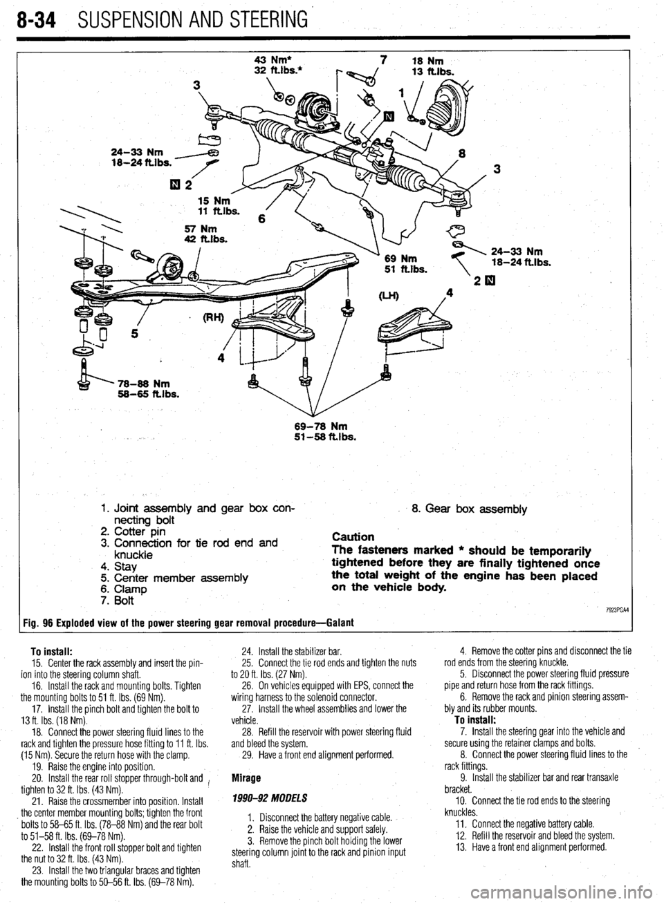
8-34 SUSPENSION AND STEERING'
Fig. 96 Exploded view of the power steering gear removal procedure- -Galant 43 Nm*
7 18 Nm
24-33 Nm
18-24 ttlbs.
15 Nm . 11 ftlbs. 6
57 Nm
42 ft.lbs.
\1- 69 Nm
51 ft.lbs. 24-33 Nm
18-24
ft.1 bs.
’ 78-86 Nm
58-65 ft.lbs.
69-78
Nm 51-58 ftlbs.
1. Joint assembly and gear box con-
necting bolt
2. Cotter pin
3. Connection for tie rod end and
knuckle
4. Stay
5. Center member assembly
6. Clamp
7. Bott
I 8. Gear box assembly
Caution
The fasteners marked * should be temporarily
tightened before they are finally tightened once
the total weight of the engine has been placed
on the vehicle
body.
7923PGAl
To install:
15. Center the rack assembly and insert the pin-
ion into the steering column shaft.
16. Install the rack and mounting bolts. Tighten
the mounting bolts to 51 ft. Ibs. (69 Nm).
17. Install the pinch bolt and tighten the bolt to
13 ft. Ibs. (18 Nm).
18. Connect the power steering fluid lines to the
rack and tighten the pressure hose fitting to 11 ft. Ibs.
(15 Nm). Secure the return hose with the clamp.
19. Raise the engine into position.
20. Install the rear roll stopper through-bolt and I
tighten to 32 ft. Ibs. (43 Nm).
21. Raise the crossmember into position. Install
_ the center member mounting bolts; tighten the front
bolts to 58-65 ft. Ibs. (78-88 Nm) and the rear bolt
to 51-58 ft. Ibs. (69-78 Nm).
22. Install the front roll stopper bolt and tighten
the nut to 32 ft. Ibs. (43 Nm).
23. Install the two triangular braces and tighten
the mounting bolts to 50-56 ft. Ibs. (69-78 Nm). 24. Install the stabilizer bar.
25. Connect the tie rod ends and tighten the nuts
to 20 ft. Ibs. (27 Nm).
26. On vehicles equipped with EPS, connect the
wiring harness to the solenoid connector.
27. Install the wheel assemblies and lower the
vehicle.
28. Refill the reservoir with power steering fluid
and bleed the system.
29. Have a front end alignment performed.
Mirage
1990-92 MODELS
I. Disconnect the battery negative cable.
2. Raise the vehicle and support safely.
3. Remove the pinch bolt holding the lower
steering column joint to the rack and pinion input
shaft. 4. Remove the cotter pins and disconnect the tie
rod ends from the steering’knuckle.
5. Disconnect the power steering fluid pressure
pipe and return hose from the rack fittings.
6. Remove the rack and pinion steering assem-
bly and its rubber mounts.
To install:
7. Install the steering gear into the vehicle and
secure using the retainer clamps and bolts.
8. Connect the power steering fluid lines to the
rack fittings.
9. Install the stabilizer bar and rear transaxle
bracket.
10. Connect the tie rod ends to the steering
knuckles.
ll= Connect the negative battery cable.
12. Refill the reservoir and bleed the system.
13. Have a front end alignment performed.
Page 331 of 408
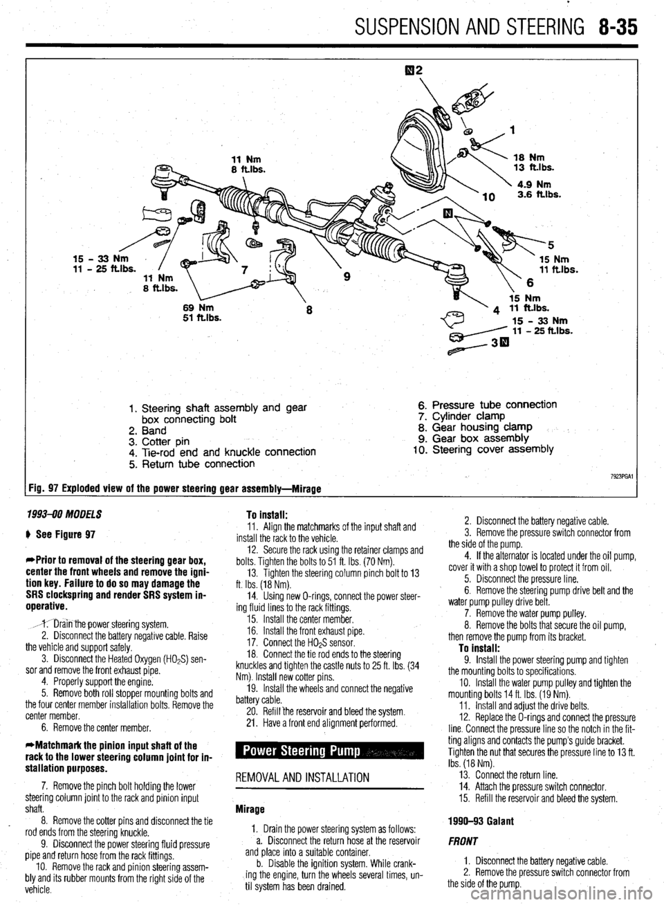
SUSPENSION AND STEERING 8-35
1. Steering shaft assembly and gear
box connecting bolt
2. Band
3. Cotter pin
4. Tie-rod end and knuckle connection
5. Return tube connection 6. Pressure tube connection
7. Cylinder clamp
8. Gear housing clamp
9. Gear box assembly 10. Steering cover assembly
7923PGAl FiD= 97 Exploded view of the power steering gear assembly-Mirage
1993-90 MODELS To install:
) See Figure 97
*Prior to removal of the steering gear box,
center the front wheels and remove the igni-
tion key. Failure to do so may damage the
SRS clockspring and render SRS system in-
operative.
,mr;iin thepower steering system.
2. Disconnect the battery negative cable. Raise
the vehicle and support safely.
3. Disconnect the Heated Oxygen (HOPS) sen-
sor and remove the front exhaust pipe.
4. Properly support the engine.
5. Remove both roll stopper mounting bolts and
the four center member installation bolts. Remove the
center member.
6. Remove the center member. 11. Align the matchmarks of the input shaft and
install the rack to the vehicle.
12. Secure the rack using the retainer clamps and
bolts. Tighten the bolts to 51 ft. Ibs. (70 Nm).
13. Tighten the steering column pinch bolt to 13
ft. Ibs. (18 Nm).
14. Using new O-rings, connect the power steer-
ing fluid lines to the rack fittings.
15. Install the center member.
16. Install the front exhaust pipe.
17. Connect the H02S sensor.
18. Connect the tie rod ends to the steering
knuckles and tighten the castle nuts to 25 ft. Ibs. (34
Nm). Install new cotter pins.
19. Install the wheels and connect the negative
battery cable.
20. Refill ‘the reservoir and bleed the system.
21. Have a front end alignment performed.
stallation purposes. -
7. Remove the pinch bolt holding the lower REMOVALANDINSTALLATION
steering column joint to the rack and pinion input
shaft.
8. Remove the cotter pins and disconnect the tie
rod ends from the steering knuckle.
9. Disconnect the power steering fluid pressure
pipe and return hose from the rack fittings.
IO. Remove the rack and pinion steering assem-
bly and its rubber mounts from the right side of the
vehicle. Mirage
1, Drain the power steering system as follows:
a. Disconnect the return hose at the reservoir
and place into a suitable container.
b. Disable the ignition system. While crank-
ing the engine, turn the wheels several times, un-
til system has been drained. 2. Disconnect the battery negative cable.
3. Remove the pressure switch connector from
the side of the pump.
4. If the alternator is located under the oil pump,
cover it with a shop towel to protect it from oil.
5. Disconnect the pressure line.
6. Remove the steering pump drive belt and the
water pump pulley drive belt.
7. Remove the water pump pulley.
8. Remove the bolts that secure the oil pump,
then remove the pump from its bracket.
To install: 9. Install the power steering pump and tighten
the mounting bolts to specifications.
IO. Install the water pump pulley and tighten the
mounting bolts 14 ft. Ibs. (19 Nm).
11. Install and adjust the drive belts.
12. Replace the O-rings and connect the pressure
line. Connect the pressure line so the notch in the fit-
ting aligns and contacts the pump’s guide bracket.
Tighten the nut that secures the pressure line to 13 ft.
Ibs. (18 Nm).
13. Connect the return line.
14. Attach the pressure switch connector.
15. Refill the reservoir and bleed the system.
1990-93 Galant
FRONT
1. Disconnect the battery negative cable.
2. Remove the pressure switch connector from
the side of the pump.