1900 MITSUBISHI DIAMANTE battery replacement
[x] Cancel search: battery replacementPage 320 of 408
SUSPENSION AND STEERING 8-25
1994-00 Galant and 1997-00 Diamante
4. Remove the retainer bolts and the stabilizer
..- 8, Loosely in”,“,, +I?,, r+&,il;7nr kn- h.~r.l,,d” -..
1. Raise and safely support the vehicle securely he bushing.
the vehicle.
on jackstands.
7er hnr with FI wmnph Remnun (1 Alinn th
2. Remove the wheel and tire assembly.
3. Support the rear axle using a jack or other
suitable device.
4. Remove the trailing arm-to-knuckle connec-
tion,
5. Remove the trailing arm-to-body mounting
n~~““yll-““!~ (1II” fWll”“C LllG llcllllll$j a,,,,. To install:
6. Install the trailing arm and install the trailing
arm-to-body mounting through-bolt. Tighten the bolt
to 99-114 ft. Ibs. (137-157 Nm).
7. Install the trailing arm-to-knuckle connection. Dar brackets. Hemove t
5. Hold the stabilL_. __. . . _ . .._..“... ..I . .._._
the self-locking nut.
6. Once the stabilizer bar nut is removed, re-
move the joint cups and stabilizer rubber bushing.
7. Hold the stabilizer link with a wrench and re-
move the self-locking nuts. Remove the stabilizer
link.
8. Lower the jack supporting the rear axle
in a slight gap between the rear sus-
? body of the vehicle.
! the stabilizer bar.
IL_ L__ I__ _)----- .-- .-J JAI.... slightly. Mainta
pension and thf
9. Remow
10. Inspect LIIB uar 101 uamage, wear ana aereno-
ration and replace as required.
-Fe c--a-...
1 IIIJMII UK 3La”III‘w “ill “lduKm “II
“. , ,,LY,, ,,ie side locating markings on the stabi-
lizer bar, so that the marking on the bar extends ap-
proximately 0.39 inches (1Omm) from the outer edge
of the mounting bracket, on both sides.
10. With the stabilizer bar properly aligned,
tighten the mounting bracket bolts to 28 ft. Ibs. (39
Nm).
11. Connect the stabilizer links to the damper fork
andihe stabilizer bar. Tighten the locking nuts to 28
ft. Ibs. (38 Nm).
12. Lower the vehicle and connect the negative
8.. Ia
mery came.
Tighten the bolt to 85-99 ft. Ibs. (118-137 Nm).
nemove me axle suppon
9. Install the wheel and tire
10. Lower the vehicle. aewce.
assembly.
I 0 Insran: 11, Install the stabilizer bar into the vehicle. Raise
the rear axle and suspension into place.
12. Install the stabilizer link into the stabilizer ba
Ir
ADJUSTMENT anfi indc4ll 33 ft. Ibs. (45 Nm).
13. Install the ioint __-_ _.._ __
1. Raise and safely support the vehicle securely the link. Ins’
..I.,
Mlhiln hnlrii, tall a rkW self~locking n
lll~llG llUlulng the stabi” ” ’ ’ ’
wrench, tighten the self,
of the stabilizer link is v
ihe hub and bearing assembly.
5. Support the rear axle using a jack or other
suitable device.
6. Remove the lower shock absorber-to-trailing
arm connection. ocking nut. Tighten the nut to
ClrnC 2nd ?$bilizer rubber to
ut onto the link.
nzer nnK oall studs with a
-locking nut so the protrusion
within 0.354-0.433 in.
I stabilizer bar bushings,
>+nn thn hnk In -I A u (9-llmm).
14. Install the cente
brackets and bolts. Tiqt Mirage
*Never disassemble the rear hub bearing.
The wheel bearing is serviced by replace-
ment of the hub.
1. Raise and safely support the vehicle.
2. Remove the rear wheel.
3. Remove the caliper and brake disc of brake 1992-96 biamante
on IacKsranos.
2. Remove the wheel and tire assembly
3, Remove thn hralm rntnr 4. Remove1
7. Remove the stabilizer bar link-to-trailing arm
connection.
8. Remove the tie rod end-to-trailing arm con-
nection.
9. Remove the lower control arm-to-trailing arm
connection.
10. Remove the trailing arm-to-body mounting
through-bolt and remove the trailing arm. Nm).
15. Install the parking
sensor installation bolt.
, , I oraxe cat * ale ar
member bracket and tighten
i Nm). Tighten the crossmem-
A to 94 ft. Ibs. (130 Nm). 16. Install the cross
the bolt to 61 ft. Ibs. (8!
ber bracket mounting nl
17. Install the rubbe
locking nuts onto the cro:
the nuts to 80-94 fl. Ibs. (
18. Lower the vehicle. id rear speed drum.
4. Remove the dust cab and tighten the flange ll”, *lb+ to 130 ft. Ibs. (180 Nm).
5. Using a dial indicator, measure wheel bear-
!r insulators and new seif-
ismemoer ’ brackets. Tighten
[110-130 Nm). ing end-play. The maximum limit for end-play is
o.oc-- ‘^ -- rzu mcnes (u.usmm).
arol
tanc
sisk 6. Using a spring scale and a rope wrapped
md the bolts, measure the rotary sliding resis-
e of the bearing/hub. The maximum limit for re-
mce is 4 Ibs. (19 N).
7. If any of the readings exceed the specifica-
To install:
11. Install the trailing arm and install the trailina Diamante and 1994-98 Gal&i
t tions, replacement of the hub is required.
8. Install the dust cap.
9. Install the brake disc and caliper, or brake
negative battery ( sble.
;“I,-.
I support the vbhlblG.
stabilizer links by removing
Alizer bar mounting brackets
from the vehicle.
lonents for wear or damage,
ded. drum.
10. Install the rear wheel assembly and lower the
vehicle to the floor.
*
1990-93 Galant
*Vehicles equipped with rear disc brakes
use a sealed hub and bearing assembly,
which requires no adjustment. Drum brake
models are
adjusted using the following pro- arm-to-body mounting through-bolt. Tighten the bolt
to 101-116 ft. Ibs. (140-160 Nm). ) See Figure 72
12. Install the trailing arm-to-lower control arm
1. Disconnect the I
connection. Tighten the bolt to 101-116 ft. Ibs.
(140-160 Nm). 2. Raise and safely
13. Install the tie rod end-to-trailing arm connec- 3. Disconnect the I
tion. Tighten the nut to 21 ft. Ibs. (29 Nm). the self-locking nuts.
14. Install the stabilizer bar link-to-trailing arm 4. Remove the stat
connection. Tighten the nut to 29 ft. Ibs. (40 Nm). and bushings.
15. Install the lower shock absorber-to-trailing
5. Remove the bar
arm connection. Tighten the bolt to 65 ft. Ibs. (90 6. Inspect all comr
. and replace parts as nee
Nrn).
16. Remove the axle support device.
17. Install the hub and bkaring assembly,
18. Install the brake rotor.
19. Install the wheel and tire assembly.
20. Lower the vehicle.
REMOVALANDINSTALLATION
1990-93 Gaiant
1. Raise and support the vehicle safely.
2. Place a jack under the rear axle and suspen- To install:
7 InstA the dnhili cedure. ._._ . . .._ -.--.. lzer bar into the vehicle.
1. Raise the vehicle and support it safely.
2. Remove the wheel and tire assemblies.
3. If equipped with rear disc brakes, remove the
caliper assembly.
4. Remove the grease cap and the hub nut.
5. Tighten the wheel bearing nut to 20 ft. Ibs. (27
Nm) while rotatir ” ”
6. Back off th
load and then tighten it to 7 ft. Ibs. (10 Nm).
7. Install the nut lock and a new cotter pin.
8. If brake caliper was removed, reinstall.
9. Install the wheel and lower the vehicle.
Diamante and lQQ44 Galant 10 tne mum/hub.
ie adjusting nut to remove the pre-
Sian assembly.
3. Remove the self-locking nuts and crossmem-
ber bracket.
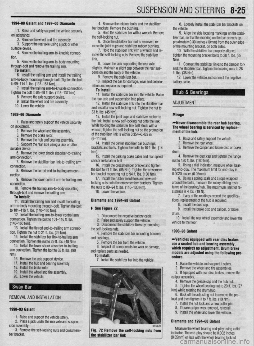
93158P61 Fig. 72 Remove the self-locking nuts from Measure the wheel bearing end-play using a dial
the stabilizer bar link indicator. The end-play should be 0.002 inches
a (0.05mm) or less with the wheel bearing locknut
Page 356 of 408
‘I
9-20 ,BRAKES
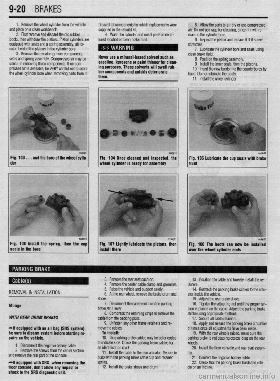
1. Remove the wheel cylinder from the vehicle
and place on a clean workbench.
2. First remove and discard the old rubber
boots, then withdraw the pistons. Piston cylinders are
equipped with seals and a spring assembly, all lo-
cated behind the pistons in the cylinder bore.
3. Remove the remaining inner components,
seals and spring assembly. Compressed air may be
useful in removing these components. If no com-
pressed air is available, be VERY careful not to score
the wheel cylinder bore when removing parts from it. Discard all components for which replacements were
supplied in the rebuild kit.
4. Wash the cylinder and metal parts in dena-
tured alcohol or clean brake fluid.
Never use a mineral-based solvent such as
gasoline, kerosene or paint thinner for clean-
ing purposes. These solvents will swell rub-
ber components and quickly deteriorate
them. 5. Allow the parts to air dry or use compressed
air. Do not use rags for cleaning, since lint will re-
main in the cylinder bore.
6. Inspect the piston and replace it if it shows
scratches.
7. Lubricate the cylinder bore and seals using
- clean brake fluid.
8. Position the spring assembly.
9. Install the inner seals, then the pistons.
IO. Insert the new boots into the counterbores bv
hand. Do not lubricate the boots,
11, Install the wheel cylinder,
m9017 Fig. 103. . .
and the bore of the wheel cylin- der
-9P20 Fig. 106 Install the spring, then the cup
seals in the bore 1 Fig. 104 Once cleaned and inspected, the
1 wheel cylinder Is ready for assembly
1 install them Fig 107 Lightly lubricate the pistons z
’ Fig. 108 The boots can now be instaT:
over the wheel cylinder ends
REMOVAL& INSTALLATION
Mirage
WITH REAR DRUM BRAKES
-If equipped witti an air bag (SRS system), 3. Remove the rear seat cushion.
13. Position the cable and loosely install the re-
4. Remove the center cable clamp and grommet.
tainers.
5. Raise the vehicle and support safely.
14. Reattach the parking brake cables to the actu-
6. At the rear wheel, remove the brake drum and
ator inside the vehicle.
shoes.
15. Adjust the rear brake shoes.
7. Disconnect the cable end from the parking
16. Tighten the adjusting nut until the proper ten-
brake strut lever.
sion is placed on the cable. Adjust the parking brake
8. Compress the retaining strips to remove the
stroke using appropriate method.
cable from the backing plate.
17. Secure all cable retainers,
9. Unfasten any other frame retainers and re-
18. Apply and release the parking brake a number
move the cables.
of times once all adjustments have been made.
be sure to disarm system
befok starting rd-
aairs on the vehicle. To install:
10. The parkinq brake cables mav be color coded 19. With the rear wheels raised, make sure the
oarkino brake is not causina excess draa on the rear
1. Disconnect the negative battery cable.
2. Remove the screws from the center section
and remove the rear part of the console.
*If equipped with SRS, when removing the
floor console,
don’t allow any impact or
shock to the SRS diagnostic unit. to indicate stde. Check the parking brake cables for
wheels: .A
an identification mark.
20. Install the floor consoleand rear seat assem-
11. Install the cable to the rear actuator. Secure in
bly.
place with the parking brake cable clip and retainer
21. Connect the negative battery cable.
spring.
22. Check that the parking brake holds the vehi-
12. Install the brake shoes and drum.
cle on an incline.
Page 372 of 408
10-4 BODYANDTRIM
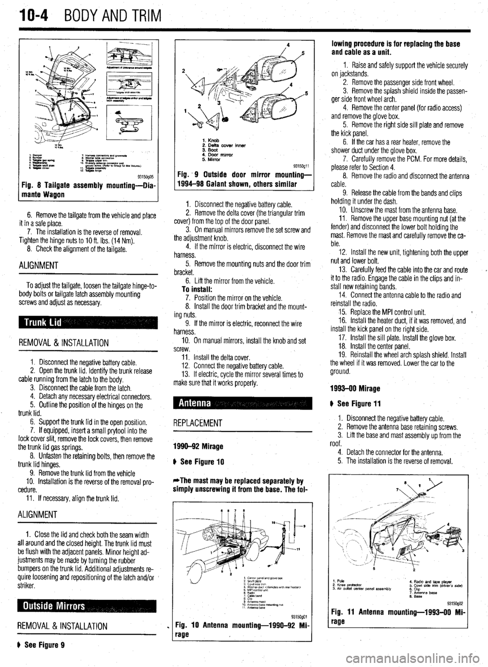
Fig. 8 Tailgate assembly mounting-Dia-
mante Wagon
6. Remove the tailgate from the vehicle and place
it in a safe place.
7. The installation is the reverse of removal.
Tighten the hinge
nuts to IO ft. Ibs. (14 Nm).
8. Check the alignment of the tailgate.
ALIGNMENT
To adjust the tailgate, loosen the tailgate hinge-to-
body bolts or tailgate latch assembly mounting
screws and adjust as necessary.
REMOVAL &INSTALLATION
1. Disconnect the negative battery cable.
2. Open the trunk lid. Identify the trunk release
cable running from the latch to the body.
3. Disconnect the cable from the latch.
4. Detach any necessary electrical connectors.
5. Outline the position of the hinges on the
trunk lid.
6. Support the trunk lid in the open position.
7. If equipped, insert a small prytool into the
lock cover slit, remove the lock covers, then remove
the trunk lid gas springs.
8. Unfasten the retaining bolts, then remove the
trunk lid hinges.
9. Remove the trunk lid from the vehicle
10. Installation is the reverse of the removal pro-
cedure.
11. If necessary, align the trunk lid.
ALIGNMENT
1. Close the lid and check both the seam width
all around and the closed height. The trunk lid must
be flush with the adjacent panels. Minor height ad-
justments may be made by turning the rubber
bumpers on the trunk lid. Additional adjustments re-
quire loosening and repositioning of the latch and/or
striker.
REMOVAL &INSTALLATION
? See Figure 9
1. Knob 2. Delta cover inner
3. Boot
4. Door mirror
5. Mirror
Fig. .9 Outside door mirror
1994-98 Galant shown
, others 9315oQ1 i mounting-
similar
1. Disconnect the negative battery cable.
2. Remove the delta cover (the triangular trim
cover) from the top of the door panel.
3. On manual mirrors remove the set screw and
the adjustment knob.
4. If the mirror is electric, disconnect the wire
harness.
5. Remove the mounting nuts and the door trim
bracket.
6. Lift the mirror from the vehicle.
To install: 7. Position the mirror on the vehicle.
8. Install the door trim bracket and the mount-
ing nuts.
9. If the mirror is electric, reconnect the wire
harness.
IO. On manual mirrors, install the knob and set
screw.
11. Install the delta cover.
12. Connect the negative battery cable.
13. If electric, cycle the mirror several times to
make sure that it works properly.
# See Figure 11
REPLACEMENT
1990-92 Mirage
b
See Figure 10
*The mast may be replaced separately by
simply unscrewing it from the base. The fol-
1. center panel and glove box
2 scuff plate
3 cowl 51ae wm
4 Washer duct
7 CaMeband
8 cap
9 Anrsnna mast
10 Antenna base “ourmng ““f
11 Antennz.base
%i%Qol
Fig. 10 Antenna mounting-1990-92 Mi-
rage lowing procedure is for replacing the base
and cable as a unit.
1 I Raise and safely support the vehicle securely
on jackstands.
2. Remove the passenger side front wheel.
3. Remove the splash shield inside the passen-
ger side front wheel arch.
4. Remove the center panel {for radio access)
and remove the glove box.
5. Remove the right side sill plate and remove
the kick panel.
6. If the car has a rear heater, remove the
shower duct under the glove box.
7. Carefully remove the PCM. For more details,
please refer to Section 4.
8. Remove the radio and disconnect the antenna
cable.
9. Release the cable from the bands and clips
holding it under the dash.
10. Unscrew the mast from the antenna base.
II. Remove the upper base mounting nut (at the
fender) and disconnect the lower bolt holding the
mast. Remove the mast and carefully remove the ca-
ble.
12. Install the new unit, tightening both the upper
nut and lower bolt.
13. Carefully feed the cable into the car and route
it to the radio. Engage the cable in the clips and in-
stall new retaining bands.
14. Connect the antenna cable to the radio and
reinstall the radio.
15. Replace the MPI control unit. t
16. Install the heater duct, if it was removed, and
install the kick panel on the right side.
17. Install the sill plate. Install the glove box.
18. Install the center panel.
19. Reinstall the wheel arch splash shield. Install
the wheel if it was removed. Lower the car to the
ground.
1993-00 Mirage
I. Disconnect the negative battery cable.
2. Remove the antenna base retaining screws.
3. Lift the base and mast assembly up from the
roof.
4. Detach the connector for the antenna.
5. The installation is the reverse of removal.
1. Pole
2. Knee protactor
3. Air outlet center panel assembly 4. Radto and laps player
5. Cowl side trim (driver’s side)
6. Chp
7. Antenna base
6. Base
931 !iogo2 Fig. 11 Antenna mounting-1993-00 Mi-
rage
Page 380 of 408
.
1042 BODYANDTRIM
P
I. i%lllUVt: LIE UUUI yldbb Uy lllllll!J It up ana out ot me ease, wnicn IS glueo onto tne wmasnlela. 1 ne
of the door.
installation is the reverse of the removal procedure. If
8. Remove the installation bolts holding the
the mirror base falls off of the windshield it can be in-
regulator to the door.
stalled as follows:
I
9. If equipped with electric windows discnnnad
1. Scrape the base mounting area with a razor
LllC vvllllly L” t,te Wlll”“W lll”l”l.
blade to remove the old adhesive.
I 10. Remove the regulator through the access hole
2. Thoroughly clean the base mounting ara.
’ in the door.
3. Obtain a mirror adhesive kit. Apply the clean-
To install:
ing compound to the windshield in the area that the
11. When reinstalling the regulator, apply a light
base is to be mounted. Allow to dry.
coat of multipurpose grease to the moving parts.
4. Apply the adhesive to both the base plate and
12. Install the regulator and tighten the bolts fin-
the windshield. Install the base to the glass. Hold in
ger-tight.
position until the adhesive has a chance to set. Make
5315oQ18 Fig. 52 To access the door components,
peel back the plastic weatherproofing 13. Beginning with the lower left bolt, final
tighten the regulator retaining bolts and p
clockwise pattern.
14.
applic
+r roceed in a
Connect the wiring to the window motor, if
able.
Install the window glass. If the vehicle is a
lack, tighten the rearmost glass mount first. If
hicle is a sedan, tighten the front bolt first.
.
13. hatcht
the ve’
16. Uperate the window a little bit at a time,
checking the fit of the glass in all dimensions and all
positions. The window should fit evenly in all chan-
nels and operate smoothly throughout its travel. Ad-
ius~ment is rener;IIIv not needed. and diffirlllf +n nor- . ._ ~ _.._. - ., _.
___.-, - - _ lll”“ll I” pm
i&h. If adiustment is necessarv, remove thp win&N I..” . . . ..“1.. regulator and elongate the mointing holes in the
door. Before this measure is undertaken, check care-
fully for bent or damaged components.
17. Reinstall the moisture barrier and the door sure the correct side of the base is installed against
the glass.
5. Allow around 24 hours for the adhesive to dry
completely before installing the mirror to the base
plate. This will assure proper adhesion.
REMOVAL & INSTALLATION
Front Seats
* err ei
I ovv rlgure 57 .
1, Disconnect the negative battery cable.
2. If equipped with power seats and the motor
doesn’t work, perform the following to slide the seat
panel.
18. Conned the negative battery Cable. in order to acdess the retainers:
-
a. Unfasten the bolts that secure the gear box
to the left and right ends of the rails.
b. Remove the gear shaft from the left side.
Pull the gear box at the right side toward you, to
I REMOVAL & INSTALLATION detach the gear from the side rail.
c. Use your hand to push the seat to a posi-
tion where the mounting nuts and bolts can be
The window motor is an integral part nf the renlrla-
romnvPrl
-’ .“- ‘-J-.- tor assembly. Refer to the door Glass and window
regulator assembly procedure above. IYII,“.““. 3. Remove the seat anchor covers.
4. Detach the electrical connector from the seat,
if m~innd I I, “y”y~Y”. 5. Unfasten the seat mountina nuts and bolts.
1 REPLACEMENT To install:
c
b Ser f Floure 56
Yap- ~~
Remove the inner rear view mirror by loosening
the set screw on the mirror stem and lifting mirror off seat adjusters on both sides of the seat are locked in
rmritinn p”3111”ll.
7. Provisionally tighten the front mounting nuts
first. After the front fasteners have been tightened,
tomnnr.,rilw tinhton thn co.-ar co.,+ m qunting bolts. then remove the seat from the vehicle.
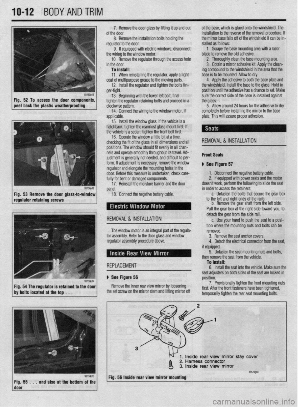
1, Inside rear view mirror stay ‘cover
2. Harness connector
3. Inside rear view mirror
’ ~;f!i!i...andalsoatthebottom~~~~ Fig. 56 Inside rear view mirror mbuntlng
I
Page 390 of 408
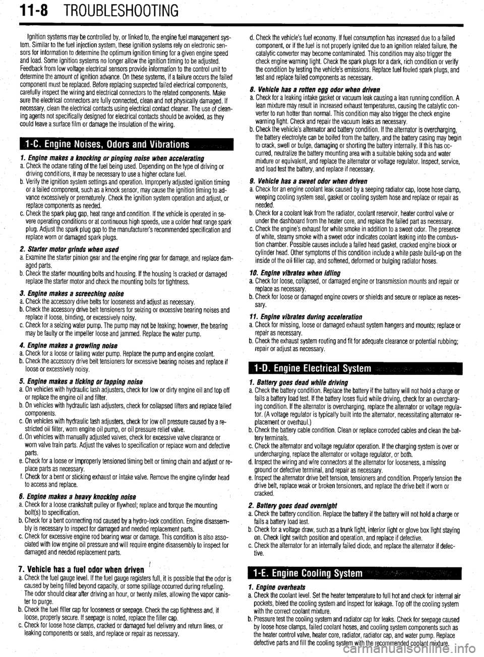
11-8 TROUBLESHOOTING
Ignition systems may be controlled by, or linked to, the engine fuel management sys-
tem. Similar to the fuel injection system, these ignition systems rely on electronic sen-
sors for information to determine the optimum ignition timing for a given engine speed
and load. Some ignition systems no longer allow the ignition timing to be adjusted.
Feedback from low voltage electrical sensors provide information to the control unit to
determine the amount of ignition advance. On these systems, if a failure occurs the failed
component must be replaced. Before replacing suspected failed electrical components,
carefully inspect the wiring and electrical connectors to the related components. Make
sure the electrical connectors are fully connected, clean and not physically damaged. If
necessary, clean the electrical contacts using electrical contact cleaner. The use of clean-
ing agents not specifically designed for electrical contacts should be avoided, as they
could leave a surface film or damage the insulation of the wiring.
1. Engine makes a knocking or pinging noise when accelerating
a. Check the octane rating of the fuel being used. Depending on the type of driving or
driving conditions, it may be necessary to use a higher octane fuel.
b. Verify the ignition system settings and operation. Improperly adjusted ignition timing
or a failed component, such as a knock sensor, may cause the ignition timing to ad-
vance excessively or prematurely. Check the ignition system operation and adjust, or
replace components as needed.
c. Check the spark plug gap, heat range and condition. If the vehicle is operated in se-
vere operating conditions or at continuous high speeds, use a colder heat range spark
plug. Adjust the spark plug gap to the manufacturer’s recommended specification and
replace worn or damaged spark plugs.
2. Sfarter motor grinds when used
a. Examine the starter pinion gear and the engine ring gear for damage, and replace dam-
aged parts.
b. Check the starter mounting bolts and housing. If the housing is cracked or damaged
replace the starter motor and check the mounting bolts for tightness.
3. Engine makes a screeching noise
a. Check the accessory drive belts for looseness and adjust as necessary.
b. Check the accessory drive belt tensioners for seizing or excessive bearing noises and
replace if loose, binding, or excessively noisy.
c. Check for a seizing water pump. The pump may not be leaking; however, the bearing
may be faulty or the impeller loose and jammed. Replace the water pump.
4. Engine makes a growling noise
a. Check for a loose or failing water pump. Replace the pump and engine coolant.
b. Check the accessory drive belt tensioners for excessive bearing noises and replace if
loose or excessively noisy.
5. Engine makes a ticking or tapping noise
a. On vehicles with hydraulic lash adjusters, check for low or dirty engine oil and top off
or replace the engine oil and filter.
b. On vehicles with hydraulic lash adjusters, check for collapsed lifters and replace failed
components.
c. On vehicles with hydraulic lash adjusters, check for low oil pressure caused by a re-
stricted oil filter, worn engine oil pump, or oil pressure relief valve.
d. On vehicles with manually adjusted valves, check for excessive valve clearance or
worn valve train parts. Adjust the valves to specification or replace worn and defective
parts.
e. Check for a loose or improperly tensioned timing belt or timing chain and adjust or re-
place parts as necessary.
f. Check for a bent or sticking exhaust or intake valve. Remove the engine cylinder head
to access and replace.
6. Engine makes a heavy knocking noise
a. Check for a loose crankshaft pulley or flywheel; replace and torque the mounting
bolt(s) to specification.
b. Check for a bent connecting rod caused by a hydro-lock condition. Engine disassem-
bly is necessary to inspect for damaged and needed replacement parts.
c. Check for excessive engine rod bearing wear or damage. This condition is also asso-
ciated with low engine oil pressure and will require engine disassembly to inspect for
damaged and needed replacement parts,
7. Vehicle has a fuel odor when driven ’ a. Check the fuel gauge level. If the fuel gauge registers full, it is possible that the odor is
caused by being filled beyond capacity, or some spillage occurred during refueling.
The odor should clear after driving an hour, or twenty miles, allowing the vapor canis-
ter to purge.
b. Check the fuel filler cap for looseness or seepage. Check the cap tightness and, if
loose, properly secure. If seepage is noted, replace the filler cap.
c. Check for loose hose clamps, cracked or damaged fuel delivery and return lines, or
leaking components or seals, and replace or repair as necessary. d. Check the vehicle’s fuel economy. If fuel consumption has increased due to a failed
component, or if the fuel is not properly ignited due to an ignition related failure, the
catalytic converter may become contaminated. This condition may also trigger the
check engine warning light. Check the spark plugs for a dark, rich condition or verify
the condition by testing the vehicle’s emissions. Replace fuel fouled spark plugs, and
test and replace failed components as necessary.
5. Vehicle has a rotten egg odor when driven
a. Check for a leaking intake gasket or vacuum leak causing a lean running condition. A
lean mixture may result in increased exhaust temperatures, causing the catalytic con-
verter to run hotter than normal. This condition may also trigger the check engine
warning light. Check and repair the vacuum leaks as necessary.
b. Check the vehicle’s alternator and battery condition. If the alternator is overcharging,
the battery electrolyte can be boiled from the battery, and the battery casing may begin
to crack, swell or bulge, damaging or shorting the battery internally. If this has oc-
curred, neutralize the battery mounting area with a suitable baking soda and water
mixture or equivalent, and replace the alternator or voltage regulator. Inspect, service,
and load test the battery, and replace if necessary.
9. Vehicle has a sweet odor when driven
a. Check for an engine coolant leak caused by a seeping radiator cap, loose hose clamp,
weeping cooling system seal, gasket or cooling system hose and replace or repair as
needed.
b. Check for a coolant leak from the radiator, coolant reservoir, heater control valve or
under the dashboard from the heater core, and replace the failed part as necessary.
c. Check the engine’s exhaust for white smoke in addition to a sweet odor. The presence
of white, steamy smoke with a sweet odor indicates coolant leaking into the combus-
tion chamber. Possible causes include a failed head gasket, cracked engine block or
cylinder head. Other symptoms of this condition include a white paste build-up on the
inside of the oil filler cap, and softened, deformed or bulging radiator hoses.
19. Engine vibraies when idling
a. Check for loose, collapsed, or damaged engine or transmission mounts and repair or
replace as necessary.
b. Check for loose or damaged engine covers or shields and secure or replace as neces-
sary.
11. Engine vibrates during acceleration
a. Check for missing, loose or damaged exhaust system hangers and mounts; replace or
repair as necessary.
b. Check the exhaust system routing and fit for adequate clearance or potential rubbing;
repair or adjust as necessary.
7. Battery goes dead while driving
a. Check the battery condition. Replace the battery if the battery will not hold a charge or
fails a battery load test. If the battery loses fluid while driving, check for an overcharg-
ing condition. If the alternator is overcharging, replace the alternator or voltage regula-
tor. (A voltage regulator is typically built into the alternator, necessitating alternator re-
placement or overhaul.)
b. Check the battery cable condition. Clean or replace corroded cables and clean the bat-
tery terminals.
c. Check the alternator and voltage regulator operation. If the charging system is over or
undercharging, replace the alternator or voltage regulator, or both.
d. Inspect the wiring and wire connectors at the alternator for looseness, a missing .
ground or defective terminal, and repair as necessary.
e. Inspect the alternator drive belt tension, tensioners and condition. Properly tension the
drive belt, replace weak or broken tensioners, and replace the drive belt if worn or
cracked.
2. Battery goes dead overnight
a. Check the battery condition. Replace the battery if the battery will not hold a charge or
fails a battery load test.
b. Check for a voltage draw, such as a trunk light, interior light or glove box light staying
on. Check light switch position and operation, and replace if defective.
c. Check the alternator for an internally failed diode, and replace the alternator if defec-
tive.
1. Engine overheats
a. Check the coolant level. Set the heater temperature to full hot and check for internal air
pockets, bleed the cooling system and inspect for leakage. Top off the cooling system
with the correct coolant mixture.
b. Pressure test the cooling system and radiator cap for leaks. Check for seepage caused
by loose hose clamps, failed coolant hoses, and cooling system components such as
the heater control valve, heater core, radiator, radiator cap, and water pump. Replace
defective parts and fill the cooling system with the recommended coolant mixture.
Page 403 of 408
ADJUSTMENTS 2-3
ADJUSTMENTS 2-5
ADJUSTMENTS 7-2
AIR BAG (SUPPLEMENTAL RESTRAINT SYSTEM) 6-7
AIR CONDITIONING COMPONENTS 6-11
REMOVAL & INSTALLATION 6-11
AIRCLEANER(ELEMENT) I-14
REMOVAL&INSTALLATION I-14
AIR CONDITIONING SYSTEM 1-28
ALLWHEELDRIVEMODELS l-44
ALTERNATOR 2-8
ALTERNATORPRECAUTIONS 2-8
ANTENNA IO-4
REPLACEMENT IO-4
ANTI-LOCK BRAKE SYSTEM 9-24
ANTI-LOCK CONTROL UNIT 9-27
REMOVAL & INSTALLATION 9-27
AUTOMATICTRANSAXLEASSEMBLY 7-10
ADJUSTMENTS 7-13
REMOVAL&INSTALLATION 7-10
AUTOMATIC TRANSAXLE 7-10
AUTOMATICTRANSAXLE l-36
DRAIN &REFILL l-36
FLUIDRECOMMENDATIONS l-36
LEVELCHECK l-36
PAN&FILTER SERVICE l-36
AVOIDINGTHEMOSTCOMMON MISTAKES l-2
AVOIDINGTROUBLE l-2
AXLE HOUSING ASSEMBLY 7-16
REMOVAL&INSTALLATION 7-16
BACK-UP LIGHT SWITCH 7-2
REMOVAL & INSTALLATION 7-2
BALANCE SHAFT 3-54
REMOVAL & INSTALLATION 3-54
BASIC ELECTRICAL THEORY 6-2
HOW DOES ELECTRlClTYWORK:THEWATERANALOGY 6-2
OHM'S LAW 6-2
BASIC FUEL SYSTEM DIAGNOSIS 5-2
BASIC OPERATING PRINCIPLES 9-2
DISC BRAKES 9-2
DRUMBRAKES 9-2 .
POWER BOOSTERS 9-2
BATTERY CABLES 6-7
BATTERY I-16
BATTERYFLUID I-16
CABLES I-17
CHARGING I-18
GENERALMAINTENANCE I-16
PRECAUTIONS 1-16
REPLACEMENT I-18
BELTS I-18
ADJUSTMENT I-18
INSPECTION I-18
REMOVAL &INSTALLATION 1-18
BLEEDING BRAKESYSTEM 9-7
BLEEDING THEABS SYSTEM 9-30
BLOWERMOTOR 6-7
REMOVAL &INSTALLATION 6-7
BODYLUBRICATIONANDMAINTENANCE l-43
BOLTS,NUTSANDOTHERTHREADED RETAINERS l-6
BRAKE CALIPER 9-11
OVERHAUL 9-12
REMOVAL & INSTALLATION 9-11
BRAKE DISC (ROTOR) 9-13
1
INSPECTION 9-14
REMOVAL &INSTALLATION 9-13
BRAKEDRUMS 9-16
INSPECTION 9-16
REMOVAL&INSTALLATION. 9-16
BRAKE HOSESAND LINES 9-6
REMOVAL&INSTALLATION 9-6
BRAKE LIGHT SWITCH 9-3
Page 406 of 408
l
II-24 MASTER INDEX
ADJUSTMENT 8-25
REMOVAL &INSTALLATION 8-25
HYDRAULIC CONTROL UNIT 9-25
REMOVAL & INSTALLATION 9-25
IDLE AIR CONTROLMOTOR 4-9
OPERATION 4-9
REMOVAL&INSTALLATION 4-9
TESTING 4-9
IDLESPEED 1-28
PREVENTIVEMAINTENANCE 1-28
SYSTEM INSPECTION 1-29
SYSTEMSERVlCE&REPAlR 1-28
IGNITION LOCK CYLINDER 8-29
REMOVAL & INSTALLATION 8-29
IGNITION SWITCH 8-30
REMOVAL & INSTALLATION 8-30
IGNITION COIL(s) 2-5
REMOVAL&INSTALLATION 2-6
TESTING . 2-5
IGNITION COIL 2-3
REMOVAL&INSTALLATION 2-3
TESTING 2-3
IGNITION TIMING l-25
GENERALINFORAMTION l-25
INSPECTION&ADJUSTMENT l-26
INSIDE REAR VIEW MIRROR
IO-IO
REPLACEMENT IO-IO
INSPECTION 3-55
REPLACEMENT 3-56
INSTRUMENT CLUSTER 6-17
REMOVAL&INSTALLATION 6-I;
INSTRUMENTPANEL IO-6
REMOVAL &INSTALLATION IO-6
INSTRUMENTS AND SWITCHES 6-17
INTAKE MANIFOLD 3-7
REMOVAL &INSTALLATION 3-7
INTAKEAIRTEMPERATURESENSOR 4-10
OPERATION 4-10
REMOVAL&INSTALLATION 4-11
TESTING 4-11
INTERIOR 1 O-6
JACKING I-46
. JACKING PRECAUTIONS 1-47
JUMP STARTING A DEAD BATTERY 1-44
JUMPSTARTING PRECAUTIONS l-45
JUMPSTARTING PROCEDURE l-45
KNUCKLE,HUB, AND BEARING 8-13
REMOVAL &INSTALLATION 8-13
LIGHTING 6-19
LOWER BALLJOINT 8-10
INSPECTION 8-10
REMOVAL & INSTALLATION 8-10
LOWER CONTROLARM 8-10
REMOVAL&INSTALLATION 8-10
LOWER CONTROL ARMS 8-23
REMOVAL & INSTALLATION 8-23
MACPHERSONSTRUTAND COILSPRING
8-7
OVERHAUL 8-7
REMOVAL & INSTALLATION 8-7
MAINTENANCEORREPAIR? l-2
MANIFOLDABSOLUTEPRESSURESENSOR
4-12
OPERATION 4-12
REMOVAL&INSTALLATION 4-13
TESTING 4-12
MANUAL RACK AND PINION STEERING GEAR
8-31
REMOVAL & INSTALLATION 8-31
MANUALTRANSAXLEASSEMBLY 7-2
REMOVAL & INSTALLATION. 7-2
MANUAL TRANSAXLE 7-2 MANUALTRANSAXLE l-35
DRAIN &REFILL l-36
FLUID RECOMMENDATIONS l-35
LEVEL CHECK l-35
MASSAIRFLOWSENSOR 4-11
OPERATION 4-11
REMOVAL&INSTALLATION 4-11
TESTING 4-11
MASTER CYLINDER 9-3
BRAKE PEDALADJUSTMENTS 9-4
REMOVAL & INSTALLATION 9-3
MULTI-POINT FUEL INJECTION SYSTEM (MPI) 5-3
DBD-1 TROUBLE CODES 4-26
OBD-II TROUBLE CODES 4-27
OIL PAN 3-30
REMOVAL & INSTALLATION 3-30
OIL PUMP 3-33
REMOVAL & INSTALLATION 3-33
OIL PRESSURESENDING UNIT 2-12@T
REMOVAL&INSTALLATION 2-1.2
TESTING 2-12
OUTSIDE MIRRORS IO-3
REMOVAL&INSTALLATION IO-3
OXYGENSENSOR 4-8
OPERATION 4-8
REMOVAL&INSTALLATION 4-8
TESTING 4-8
PARK/NEUTRAL POSITIONSWITCH 7-10
ADJUSTMENT 7-10
REMOVAL & INSTALLATION 7-10
PARKING BRAKE 9-20
PCVVALVE l-15
REMOVAL&INSTALLATION I-15
PINION SEAL 7-16
REMOVAL &INSTALLATION 7-16
POWER BRAKEBOOSTER 9-5
REMOVAL &INSTALLATION 9-5
POWER RACK AND PINION STEERING GEAR 8-32
REMOVAL &INSTALLATION 8-32
POWERSEATMOTOR IO-11
REMOVAL & INSTALLATION IO-11
POWER STEERING PUMP 8-34
REMOVAL & INSTALLATION 8-34
SYSTEM BLEEDING 8-36
POWER TRANSlSTOR(IGNITION MODULE) 2-7
REMOVAL&INSTALLATION 2-7
POWERSTEERING PUMP l-42
FLUID RECOMMENDATIONS l-42
LEVELCHECK l-42
POWER TRANSlSTOR(Ignition Module) 2-4
REMOVAL&INSTALLATION 2-4
PRESSURERELIEFVALVE 5-9
REMOVAL&INSTALLATION 5-9
PROPORTIONING VALVE 9-6
REMOVAL & INSTALLATION 9-6 *
RADIATOR 3-18
REMOVAL &INSTALLATION 3-18
RADIO RECEIVER/AMPLIFIER/TAPE PLAYER/CD PLAYER 6-14
READING CODES 4-26
WITHASCANTOOL 4-26
WITHOUTASCANTOOL 4-27
READING CODES 4-27
WITHASCANTOOL 4-27
WITHOUTASCANTOOL 4-27
REAR AXLE DIFFERENTIAL 7-15
REAR HALFSHAFTAND SEAL 7-15
REMOVAL&INSTALLATION 7-15
REAR MAIN SEAL 3-54
REMOVAL & INSTALLATION 3-54