1900 MITSUBISHI DIAMANTE engine coolant
[x] Cancel search: engine coolantPage 59 of 408
.
2-12 ENGINEELECTRICAL
*This section describes the operating prina
ciples of sending units, warning lights and
gauges. Sensors which provide information
to the Enafne Control Unit (ECU) or Electronic
or Power&in Control Module (FCM/PCM) are
covered in Section 4 of this manual.
Instrument panels contain a number of indicating
devices (gauges and warning lights). These devices
are composed of two separate components. One is
the sending unit, mounted on the engine or other re-
mote part of the vehicle, and the other is the actual
gauge or light in the instrument panel.
Several types of sending units exist, however most
can be characterized as being either a pressure type
or a resistance type. Pressure type sending units
convert liquid pressure into an electrical signal which
is sent to the gauge. Resistance type sending units
are most often used to measure temperature and use
variable resistance to control the current flow back to
the indicatinq device. Both types of sendinq units are
connected inseries by a wimto the batteryithiough
the ignition switch). When the ignition is turned ON,
current flows from the battery through the indicating
device and on to the sending unit.
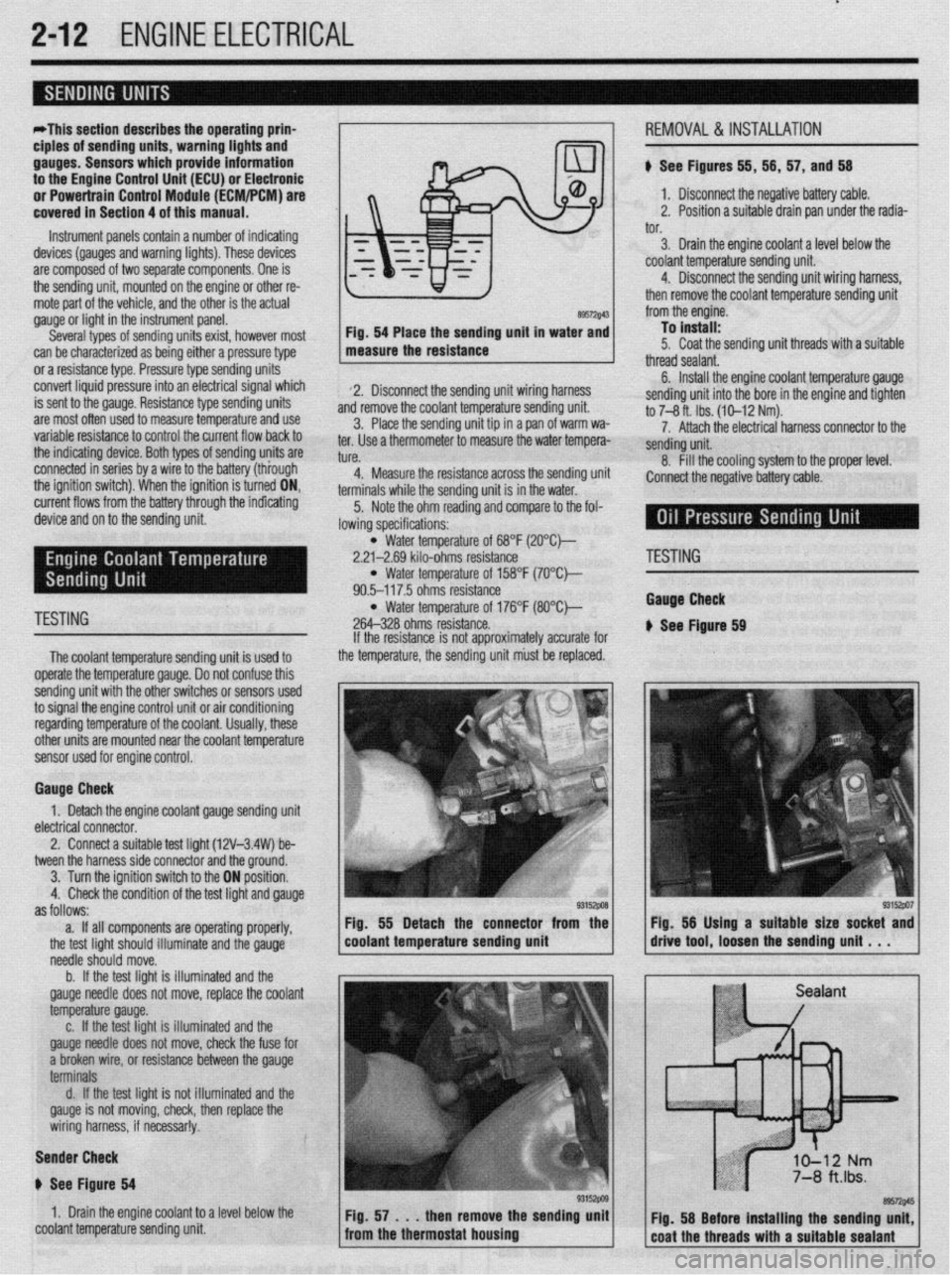
89572$43 Fig. 54 Place the sending unit in water and
measure the resistance
2. Disconnect the sending unit wiring harness
and remove the coolant temperature sending unit.
3. Place the sending unit tip in a pan of warm wa-
ter. Use a thermometer to measure the water tempera-
tl KP
L”,“.
4. Measure the resistance across the sending uni
terminals while the sending unit is in the water.
5. Note the ohm reading and compare to the fol-
lowing specifications: i, 56, 57, and 56
1. Disconnect the negative battery cable.
2. Position a suitable drain pan under the radia-
tor.
3. Drain the engine coolant a level below the
coolant temperature sending unit.
4. Disconnect the sending unit wiring harness,
then remove the coolant temperature sending unit
from the engine.
To install:
5. Coat the sending unit threads with a suitable
thread sealant.
6. Install the engine coolant temperature gauge
sending unit into the bore in the engine and tighten
to 7-8 ft. Ibs. (10-12 Nm).
7. Attach the electrical harness connector to the
sendina unit.
8. fill the cooling system to the proper level.
:onnect the negative battery cable.
l Water temperature of 68°F (2O”C)-
2.21-2.69 kilo-ohms resistance
l Water temperature of 158°F (7O’Ck
90.5-117.5 ohms resistance
TESTING l Water temperature of 176°F (8O”C)-
264-328 ohms resistance.
The coolant temperature sendina unit is used to
operate the temperature gauge. Donot confuse this
sending unit with the other switches or sensors used
to signal the engine control unit or air conditioning
regarding temperature of the coolant. Usually, these
other units are mounted near the coolant temoerature
sensor used for engine control. If the resistance is not approximately accurate for
the temperature, the sending unit must be replaced.
Gauge Check
1. Detach the engine coolant gauge sending unit
electrical connector.
2. Connect a suitable test liaht (12V-3.4W) be-
tween the harness side connector and the around.
I
3. Turn the ignition switch to the ON position.
4. Check the condition of the test light and gauge
as follows:
a. If all components are operating properly,
the test light should illuminate and the gauge
needle should move.
b. If the test light is illuminated and the
gauge needle does not move, replace the coolant
temperature gauge.
c. If the test light is illuminated and the
gauge needle does not move, check the fuse for
a broken wire, or resistance between the gauge
terminals
d. If the test light is not illuminated and the
gauge is not moving, check, then replace the
wiring harness, if necessar!y.
Sender Check
p See Figure 64
1. Drain the engine coolant to a level below the
coolant temperature sending unit Fig. 55 Detach the connector from the
coolant temperature sending unit
'ESTING
tauga Check
See Ftgure 69
Page 61 of 408
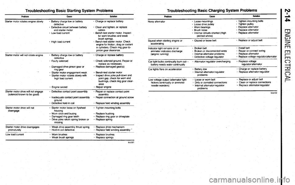
Troubleshooting Basic Starting System Problems Troubleshooting Basic Charging System Problems
Pmblem
Starter motor rotates engrne slowly cause
* Battery charge low or battery
defecttve Sobnlon
. Charge or replace battery
- Defective crrcurt between battery
and starter motor
* Low load current
* Hugh load current + Clean and ttghten, or replace
cables
* Bench-test starter motor Inspect
for wom brushes and weak
brush springs.
. Bench-test starter motor Check
engtne for fncbon, drag or coolant
rn cylinders. Check nng gear-to-
prnton gear clearance.
Starter motor wrll not rotate engrne
Starter motor dnve wrll not engage
(solenotd known to be good)
Starter motor dnve wtli not
dtsengage * Battery charge low or battery * Charge or replaoe battery
defecttve
* Faulty solenord . Check solenoid ground Reparr or
replace as necessary.
* Damaged drive pnron gear or * Replace damaged gear(s)
ring gear
* Starter motor engagement weak . Bench-test starter motor
. Starter motor rotates slowly wtth . Inspect dnve yoke pull-down and
high load current pornt gap, check for worn end
bushtngs. check m-g gear clear-
ance
. Engine setzed * Repatr engk7e
. Defecbve contact pant assembly * Reparr or replace contact pornt
assembly
. Inadequate contact pornt assembly + Repatr connectron at ground screw
ground
- Defeckve hold-In co11
* Replace field w~ndrng assembly
- Starter motor loose on flywheel . Ttghten mounttng bolts
houstng
. Worn drive end bustng . Replace bushtrg
* Damaged nng gear teeth . Replace ring gear or dnveplate
* Drive yoke return spnng broken or . Replace spnng
mtsstng
Starter motor dnve d&engages
prematurely
Low load current * Weak drive assembly thrust spnng * Replace dnve mechamsm
* Hold-tn co11 defeckve
. Replace field wtndtng assembly *
- Worn brushes . Replace brushes
* Weak brush springs * Replace spnngs Problem
Noisy alternator cause
* Loose mounbngs
. Loose drive pulley SoluIion
. Ttghten mountrng bolts
. Tighten pulley
. Worn beanngs
* Brush notse
* Internal circuits shorted (Hugh
pitched whrne) * Replace alternator
. Replace alternator
. Replace alternator
Squeal when starting engtne or . Glazed or loose belt * Replace or adfust belt
acceleratmg
Indicator light rematns on or . Broken belt . Install heft
ammeter rndrcates drscharge . Broken or dksconnected wares - Repatr or connect Waring
(ejrgrne runmng) * Internal aitemator problems * Replace alternator
. Defectrve voltage regulator . Replace vottage regulator/alternator
Car Irght bulbs contmually bum out- * Alternator/regulator overchargtng . Replace voltage
batter-v needs water conbnually regulatoriatternator
Car kghts flare on acceleratton . Battery low
. Internal alternator/regulator
problems * Charge or replace battery
. Replace alternator/regulator
Low voltage output (alternator lght
fltckers conbnually or ammeter
needle wanders) * Loose or worn belt
* Dkly or corroded connecttons
* Internal alternator/regulator
oroblems . Replace or adjust beit
. Clean or replace connecttons
* Replace alternator/regulator
Page 63 of 408
3-2 ENGINEANDENGINEOVERHAUL
REMOVAL &INSTALLATION
# See Figure 1
In the process of removing the engine, you will
come across a number of steps which call for the re-
moval of a separate component or system, such as
“disconnect the exhaust system” or “remove the radi-
ator.” In most instances, a detailed removal proce-
dure can be found elsewhere in this manual.
It is virtually impossible to list each individual
wire and hose which must be disconnected, simply
because so many different model and engrne combi-
nations have been manufactured Careful observation
and common sense are the best possible approaches
to any repair procedure.
Removal and installation of the engine can be
made easier if you follow these basic points:
l If you have to drain any of the fluids, use a
suitable container.
l Always tag any wires or hoses and, if possrble,
the components they came from before disconnect-
ing them.
l Because there are so many bolts and fasteners
involved, store and label the retainers from compo-
nents separately in muffin pans, jars or coffee cans.
This will prevent confusion during installatron.
l After unbolting the transmisston or transaxle,
always make sure it is properly supported.
l If it is necessary to disconnect the air condi-
tioning system, have this service performed by a
qualified technician using a recovery/recycling sta-
tion If the system does not have to be disconnected,
unbolt the compressor and set it aside.
l When unbolting the engine mounts, always
make sure the engine is properly supported. When
removing the engine, make sure that any lifting de-
vices are properly attached to the engine. It is recom-
mended that if your engine IS supplied with lifting
hooks, your lifting apparatus be attached to them.
l Lift the engine from its compartment slowly,
checking that no hoses, wires or other components
are still connected.
l After the engine is clear of the compartment,
place it on an engine stand or workbench.
l After the engine has been removed, you can
perform a partial or full teardown of the engine using
the procedures outlined in this manual.
1. Relieve fuel system pressure.
Observe all applicable safety precautions
when working around fuel. Whenever servic-
ing the fuel system, always work in a well
ventilated area. Do not allow fuel spray or
vapors to come in contact with a spark or
open flame. Keep a dry chemical fire extin-
guisher near the work area. Always keep fuel
in a container specifically designed for fuel
storage; also, always properly seal fuel con-
tainers to avoid the possibility of fire or ex-
plosion.
2. Disconnect the negative battery cable.
3. Remove the engine undercover if equipped. 4. Matchmark the hood and hinges and remove
the hood assembly.
5. Remove the air cleaner assembly and all ad-
joining air intake duct work.
6. Drain the engine coolant, remove the radiator
hoses, and remove the radiator assembly, coolant
reservoir, and intercooler, as equipped.
cooling system when hot; serious burns can
occur from the steam and hot coolant. Also,
when draining engine coolant, keep in mind
that cats and dogs are attracted to ethylene
glycol antifreeze and could drink any that is
left in an uncovered container or in puddles
on the ground. This will prove fatal in suffi-
cient quantities. Always drain coolant into a
sealable container. Coolant should be reused
unless it is contaminated or is several years
old.
7. Remove the transaxle and transfer case as
equipped.
8. Tag and detach the following electrical con-
nections:
l Accelerator cable l Heater hoses l Brake booster vacuum hose l Vacuum hoses l Fuel lines l Engine ground cables l Any applicable sensors l Coolant temperature and oil pressure send-
ing units
l Exhaust Gas Recirculation (EGR) tempera-
ture sensor
l Connection for the idle speed control mo-
tor
l Fuel injectors l Power transistor l Ignition coil and any applicable distributor
connections
l The connections for the alternator l Power steering pressure switch l A/C compressor l Refrigerant temperature switch l Condenser
9. Remove the air conditioner drive belt and the
air conditioning compressor. Leave the hoses at-
tached. Do not discharge the system. Place the com-
pressor aside and secure it using a suitable device.
10. Remove the power steering pump and place
the pump asrde and secure it using a surtable device.
11. Remove the exhaust manifold-to-exhaust
pipe nuts. Discard the gasket.
12. Install the engine hoist equipment and make
certain the attaching points on the engine are secure.
13. Raise the hoist enough to support the engine.
14. Remove the front and rear engine roll stop-
pers
15. Remove the left engine mount and support
Double check that all cables, hoses, harness
connectors, etc., are disconnected from the
engine.
16. Slowly lift the engine and remove it from the
vehicle.
To install:
17. Install the engine and secure all control
brackets and mounts.
18. Install the transaxle, and transfer case if
equipped.
19. The balance of the installation is the reverse
of removal with the addition of the following notes:
a. Use new clamps or O-rings to connect the
high pressure fuel lme and the fuel return line.
b. Use new gaskets to connect the exhaust
system to the engine.
c. Fill the engine with the proper amount of
engine oil and coolant.
d. Start the engine, allow it to reach normal
operating temperature.
e. Check for leaks.
f. Check the ignition timing and adjust if nec-
essary.
g. Road test the vehicle and check all fluid
levels and functions for proper operation.
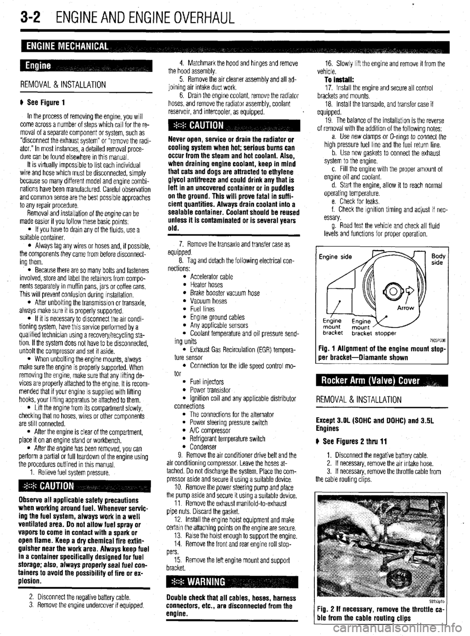
Fig. 1 Alignment of the engine mount stop-
oer bracket-Diamante shown
REMOVAL &INSTALLATION
Except 3.OL (SOHC and DOHC) and 3.5L
Engines
# See Figures 2 thru 11
1. Disconnect the negative battery cable.
2. If necessary, remove the air intake hose.
3. If necessary, remove the throttle cable from
the cable routing clips.
Fig. 2 If necessary, remove the throttle ca-
ble from the cable routing clips
Page 68 of 408
ENGINEANDENGINEOVERHAUL 3-7
4. Remove the center cover, breather and PCV
hoses, and spark plug cables.
5. Remove the rocker cover.
6. Remove the throttle body stay, both camshaft
sprockets, and oil seals.
7. Remove the Camshaft Position fCMP) sensor 3. install the lash adjuster clips on the rocker
arms, then loosen the bearing cap bolts. Do not re-
move the bolts from the bearing caps.
4. Remove the rocker arms, shafts and bearing
caps as an assembly.
lo hlstall: unless it is contaminated or is several years old.
3. Remove any necessary components to access
the thermostat.
4. Remove the thermostat housinq retaininq
nd adapter from the rear of the camshah. ’
8. Remove the intake and exhaust camshafts.
9. Remove rocker arms and lash adjusters from
he head. It is recommended that all lash adjusters
md rockers be replaced as a complete set.
To Install:
10. Immerse the lash adjusters in clean diesel
uel. Using a small wire, move the plunger of the lash
tdjuster up and down four or five times while push-
ng down lightly on the check ball in order to bleed
jut the air. Lubricate and install the lash adjusters in
he cylinder head.
11. Lubricate the camshafts with clean enqine oil
nd position the camshafts on the cylinder head.
12. Install the bearing caps. Tighten the caps in
sequence, in 2 or 3 steps. Caps 2,3 and 4 have a
ront mark. Install with the mark aligned with the front
nark on the cylinder head. Intake caps have I
stamped on the cap and exhaust caps have E. Also,
)e sure the rocker arm is correctly mounted on the
ash adjuster and the valve stem end. Torque the front
md rear retaining cap bolts to 14 ft. Ibs. (20 Nm) and
ighten the center 3 retaining cap bolts to 8 ft. Ibs.
11 Nm).
13. Apply a coating of engine oil to the oil seals
md install.
14. Install the timing belt, valve cover and all re-
ated parts. Refer to the timing belt procedure in this
;ection. 5. Install the bearing caps/rocker arm assem-
blies. Tighten the bolts to 23 ft. Ibs. (31 Nm).
6. Remove the lash adjuster clips.
7. Install the rocker arm cover using a new gas-
ket.
8. Connect the negative battery cable.
REMOVAL &INSTALLATION
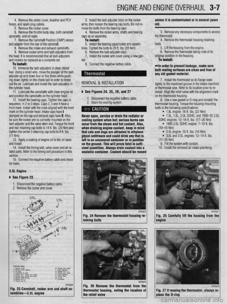
b See Figures 24, 25, 26, and 27
1. Disconnect the negative battery cable.
2. Drain the cooling system.
Never open, service or drain the radiator or
cooling system when hot; serious bums can
occur from the
steam and hot coolant. Also,
when draining engine coolant, keep in mind
that cats and dogs are attracted to ethylene
glycol antifreeze and could drink any that is
left in an uncovered container or in puddles
on the ground. This will prove fatal in suffi-
cient quantities. Always drain coolant into a
sealable container. Coolant should be reused bolts.
5. Lift the housing from the engine.
6. Remove the thermostat taking note of its
original position in the housing.
To Install:
*In order to prevent leakage, make sure
both mating
surfaces are clean and free of
any old gasket material.
7. Install the thermostat so its flange seats
tightly in the machined groove in the intake manifold
or thermostat case. Refer to its location prior to re-
moval. Aliqn the relief valve with the alignment mark
on the thermostat housing.
8. Use a new gasket or D-ring and reinstall the
thermostat housing. Torque the housing mounting
bolts to the following specifications:
l 1.8L engine: 16 ft. Ibs. (22 Nm) l 1.5L, 1.61, 2.OL DOHC, and 1990-92 2.OL
SOHC engines: 12-14 ft. Ibs. (17-20 Nm)
l 1993 2.01 SOHC engine: 7-10 ft. Ibs.
(10-15 Nm)
l 2.4L engine: IO ft. Ibs. (14 Nm) l 3.OL and 3.5L engines: 12-14 ft. Ibs.
(17-20 Nm)
9. Fill the system with coolant.
10. Install the removed air intake plumbing.
15. Connect the negative battery cable and check
or leaks.
3.51 Engine
I See Figure 23
1. Disconnect the negative battery cable.
2. Remove the rocker arm cover.
g. 26 Remove the thermostat from the
ousing, noting the location of using the thermostat, always re-
Page 69 of 408
3-8' ENGINEANDENGINEOVERHAUL
Nm ft.lbs.
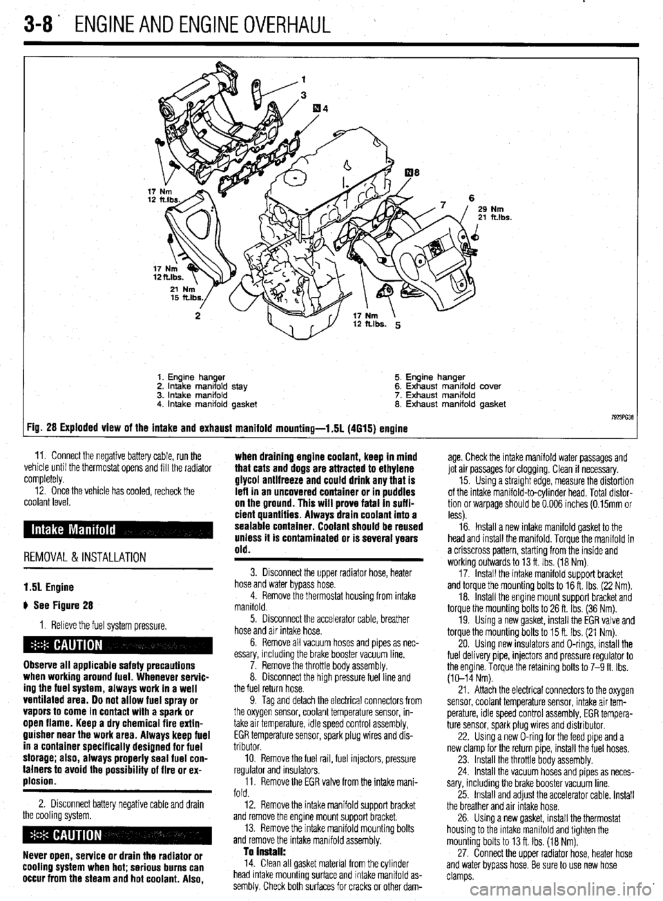
1. Engine hanger 5. Engine hanger
2. Intake manifold stay 6. Exhaust manifold cover
3. intake manifold 7. Exhaust manifold
4. Intake manifold gasket 8. Exhaust manifold gasket
7923ffi38 :ig. 28 Exploded view of the intake and exhaust manifold mounting-l .5L (4615) engine
11. Connect the negative battery cable, run the ,. . . .
vemcie unnl me tnermostat opens ano till the radiator
completely. age. Check the intake manifold water passages and
jet air passages for clogging. Clean if necessary.
12. Once the vehicle has cooled, recheck the
coolant level.
REMOVAL &INSTALLATION when draining engine coolant, keep in mind
that cats and dogs are attracted to ethylene
glycol antifreeze and could drink any that is
left in an uncovered container or in puddles
on the ground. This will prove fatal In suffi-
cient quantities. Always drain coolant into a
sealable container. Coolant should be reused
unless it is contaminated or is several years
old.
15. Using a straight edge, measure the distortion
of the intake manifold-to-cylinder head. Total distor-
tion or warpage should be 0.006 inches (0.15mm or
less).
16. Install a new intake manifold gasket to the
head and install the manifold. Torque the manifold in
a crisscross pattern, starting from the inside and
working outwards to 13 ft. Ibs. (18 Nm).
17. Install the intake manifold support bracket
and torque the mounting bolts to 16 ft. Ibs. (22 Nm).
18. Install the engine mount support bracket and
torque the mounting bolts to 26 ft. Ibs. (36 Nm).
19. Using a new gasket, install the EGR valve and
torque the mounting bolts to 15 ft. Ibs. (21 Nm).
20. Using new insulators and O-rings, install the
fuel delivery pipe, injectors and pressure regulator to
the engine. Torque the retaining bolts to 7-9 ft. Ibs.
(10-14 Nm).
1.51 Engine
# See Figure 28
1. Relieve the fuel system pressure.
Observe all applicable safety precautions
when working around fuel. Whenever servic-
ing the fuel system, always work in a well
ventilated area. Do not allow fuel spray or
vapors to come in contact with a spark or
open flame. Keep a dry chemical fire extin-
guisher near the work area. Always keep fuel
in a container specifically designed for fuel
storage; also, always properly seal fuel con-
tainers to avoid the possibility of fire or ex-
plosion.
2. Disconnect battery negative cable and drain
the cooling system.
Never open, service or drain the radiator or
cooling system when hot; serious burns can
occur from the steam and hot coolant. Also,
3. Disconnect the upper radiator hose, heater
hose and water bypass hose.
4. Remove the thermostat housing from intake
manifold.
5. Disconnect the accelerator cable, breather
hose and air intake hose.
6. Remove all vacuum hoses and pipes as nec-
essary, including the brake booster vacuum line.
7. Remove the throttle body assembly.
8. Disconnect the high pressure fuel line and
the fuel return hose.
9. Tag and detach the electrical connectors from
the oxygen sensor, coolant temperature sensor, in-
take air temperature, idle speed control assembly,
EGR temperature sensor, spark plug wires and dis-
tributor.
10. Remove the fuel rail, fuel injectors, pressure
regulator and insulators.
11. Remove the EGR valve from the intake mani-
fold.
12. Remove the intake manifold support bracket
and remove the engine mount support bracket.
13. Remove the intake manifold mounting bolts
and remove the intake manifold assembly.
To Install: 14. Clean all gasket material from the cylinder
head intake mounting surface and intake manifold as-
sembly. Check both surfaces for cracks or other dam- 21. Attach the electrical connectors to the oxygen
sensor, coolant temperature sensor, intake air tem-
perature, idle speed control assembly, EGR tempera-
ture sensor, spark plug wires and distributor.
22. Using a new O-ring for the feed pipe and a
new clamp for the return pipe, install the fuel hoses.
23. Install the throttle body assembly.
24. Install the vacuum hoses and pipes as neces-
sary, including the brake booster vacuum line.
25. Install and adjust the accelerator cable. Install
the breather and air Intake hose.
26. Using a new gasket, install the thermostat
housing to the intake manifold and tighten the
mounting bolts to 13 ft. Ibs. (18 Nm).
27. Connect the upper radiator hose, heater hose
and water bypass hose. Be sure to use new hose
clamps.
Page 70 of 408
ENGINEANDENGINEOVERHAUL 3-9
28. Fill the system with coolant.
29. Connect the negative battery cable, run the
vehicle until the thermostat opens, fill the radiator
completely.
30. Check and adjust the idle speed and ignition
timing.
31. Once the vehicle has cooled, recheck the
coolant level.
1.8L Engine
) See Figures 29 and 30
I. Relieve the fuel system pressure.
Observe all applicable safety precautions
when working around fuel. Whenever servic-
ing the fuel system, always work in a well
ventilated area. Do not allow fuel spray or
vapors to come in contact with a spark or
open flame. Keep a dry chemical fire extin-
guisher near the work area. Always keep fuel
in a container specifically designed for fuel
storage; also, always properly seal fuel con-
tainers to avoid the possibility of fire or ex-
plosion.
2. Disconnect battery negative cable and drain
the cooling system.
Never open, service or drain the radiator or
cooling system when hot; serious burns can
occur from the steam and hot coolant. Also,
when draining engine coolant, keep in mind
that cats and dogs are attracted to ethylene
glycol antifreeze and could drink any that is
leff in an uncovered container or in puddles
on the ground. This will prove fatal in suffi-
cient quantities. Always drain coolant into a
sealable container. Coolant should be reused
unless it is contaminated or is several years
old.
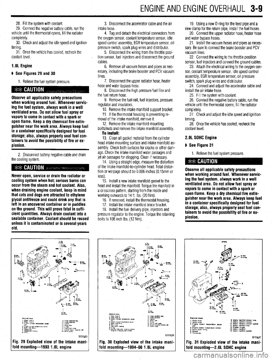
Fig. 29 Exploded view of the intake mani.
old mounting-1993 1.8L engine
3. Disconnect the accelerator cable and the air
intake hose.
4. Tag and detach the electrical connectors from
the oxygen sensor, coolant temperature sensor, idle
speed control assembly, EGR temperature sensor, oil
pressure switch, spark plug wires and distributor.
5. Disconnect the wiring from the throttle posi-
tion sensor, fuel Injectors and disconnect the ground
cables.
6. Remove all vacuum hoses and pipes as nec-
essary, including the brake booster and PCV vacuum
lines.
7. Disconnect the upper radiator hose, heater
hose and water bypass hose.
8. Disconnect the high pressure fuel line and
the fuel return hose.
9. Remove the fuel rail, fuel injectors, pressure
regulator and insulators.
10. Remove the intake manifold support bracket.
11. If the thermostat housing is preventing re-
moval of the Intake manifold, remove it.
12. Remove the intake manifold mounting
bolts/nuts and remove the intake manifold assembly.
To install: 13. Clean all gasket material from the cylinder
head intake mounting surface and intake manifold as-
sembly Check both surfaces for cracks or other dam-
age. Check the intake manifold water passages and
jet air passages for clogging. Clean if necessary.
14. Using a straight edge, measure the distortion
of the intake manifold-to-cylinder head. Total distor-
tion or warpage should be 0.006 inches (0.15mm or
less).
15. Install a new intake manifold gasket to the
head and install the manifold. Torque the manifold in
a crrsscross pattern, starting from the inside and
working outwards to 14 ft. Ibs. (20 Nm).
16. If removed, install the thermostat housing.
17. Install the Intake manifold brace bracket.
18. Install the fuel delivery pipe, injectors and
pressure regulator to the engine. Torque the retaining
bolts to 108 Inch Ibs. (12 Nm). 19. Using a new O-ring for the feed pipe and a
new clamp for the return pipe, install the fuel hoses,
20. Connect the upper radiator hose, heater hose
and water bypass hoses.
21. Install the vacuum hoses and pipes as neces-
sary. Be sure to connect the brake booster and PCV
vacuum lines
22. Connect the wiring to the throttle position
sensor, fuel injectors and connect the ground cables,
23. Attach the electrical wiring to the oxygen sen-
sor, coolant temperature sensor, Idle speed control
assembly, EGR temperature sensor, oil pressure
switch, spark plug wires and distributor.
24. Connect and adjust the accelerator cable and
install the air intake hose.
25. Fill the system with coolant.
26. Connect the negative battery cable, run the
vehicle until the thermostat opens, fill the radiator
completely.
27. Check and adjust the idle speed and ignition
timing.
28. Once the vehicle has cooled, recheck the
coolant level. 2.OL SOHC Engine
# See Figure 31
1. Relieve the fuel system pressure.
Observe all applicable safety precautions
when working around fuel. Whenever servic-
ing the fuel system, always work in a well
ventilated area. Do not allow fuel spray or
vapors to come in contact with a spark or
open flame. Keep a dry chemical fire extin-
guisher near the work area. Always keep fuel
in a container specifically designed for fuel
storage; also, always properly seal fuel con-
tainers to avoid the possibility of fire or ex-
plosion.
Fig. 30 Exploded view of the intake mani,
iold mounting-1994-00 1.8L engine Fig. 31 Exploded view of the intake mani
fold mounting-2.01 SOHC ermine
Page 71 of 408
3-10 ENGINEANDENGINEOVERHAUL
2. Disconnect the battery negative cable.
3. Drain the cooling system.
Never open, service or drain the radiator or
cooling system when hot; serious burns can
occur from the steam and hot coolant. Also,
when draining engine coolant, keep in mind
that cats and dogs are attracted to ethylene
glycol antifreeze and could drink any that is
left in an uncovered container or in puddles
on the ground. This will prove fatal in suffi-
cient quantities. Always drain coolant into a
sealable container. Coolant should be reused
unless it is contaminated or is several years
old.
4 Disconnect the accelerator cable and air in-
take hose.
5. Disconnect the upper radiator hose, heater
hose and water bypass hose.
6. Unplug the vacuum connection at the power
brake booster and the PCV valve if still connected.
Disconnect all remaining vacuum hoses and pipes as
necessary.
7. Disconnect the high pressure fuel line, fuel
return hose and remove throttle control cable brack-
ets
8. Tag and detach the electrical connectors from
the oxygen sensor, coolant temperature sensor,
therm0 switch, idle speed control assembly, EGR
temperature sensor, distributor, fuel injectors and
spark plug wires. Position the engine wiring harness
aside.
9. Matchmark the distributor housing to the in-
take manifold, and remove the distributor.
10. Remove the intake manifold bracket and the
engine hanger.
11. If the thermostat housing is preventing re-
moval of the intake manifold, remove it.
12. Remove the intake manifold mounting bolts
and remove the intake manifold assembly. Drsassem-
ble manifold from the Intake plenum on a work bench
as required
To install: 13. Clean all gasket material from the cylinder
head intake mounting surface and intake manifold as-
sembly. Check both surfaces for cracks or other dam-
age. Check the intake manifold water passages and
jet air passages for clogging. Clean if necessary.
14 Assemble the intake manifold assembly using
all new gaskets. Torque air intake plenum bolts to
11-14ff. Ibs. (15-19 Nm).
15. Install a new intake manifold gasket to the
head and install the manifold. Torque the manifold in
a crrsscross pattern, starting from the inside and
working outwards to 11-14 ff. Ibs. (15-19 Nm).
16. Install the fuel delivery pipe, injectors and
pressure regulator to the engine. Torque the retaining
bolts to 4 ft. Ibs (6 Nm).
17. install the thermostat housing, intake mani-
fold brace bracket, and engine hanger bracket.
18 Connect or install all hoses, cables and elec-
trical connectors that were removed or disconnected
during the removal procedure.
19. Align the distributor matchmarks and install
the distributor.
20. Fill the system with coolant,
21. Connect the negative battery cable, run the
vehicle until the thermostat opens, fill the radiator
completely. 22. Adjust the accelerator cable. Check and ad-
just the idle speed and ignition timing.
23. Once the vehicle has cooled, recheck the
coolant level.
1.6L and 2.OL DDHC Engines
# See Figure 32
1. Relieve the fuel system pressure.
Observe all applicable safety precautions
when working around fuel. Whenever servic-
ing the fuel system, always work in a well
ventilated area. Do not allow fuel spray or
vapors to come in contact with a spark or
open flame. Keep a dry chemical fire extin-
guisher near the work area. Always keep fuel
in a container specifically designed for fuel
storage; also, always properly seal fuel con-
tainers to avoid the possibility of fire or ex-
ulosion.
2. Disconnect battery negative cable and drain
the cooling system.
Never open, service or drain the radiator or
cooling system when hot; serious burns can
occur from the steam and hot coolant. Also,
when draining engine coolant, keep in mind
that cats and dogs are attracted to ethylene
glycol antifreeze and could drink any that is
left in an uncovered container or in puddles
on the ground. This will prove fatal in suffi-
cient quantities. Always drain coolant into a
sealable container. Coolant should be reused
unless it is contaminated or is several years
old.
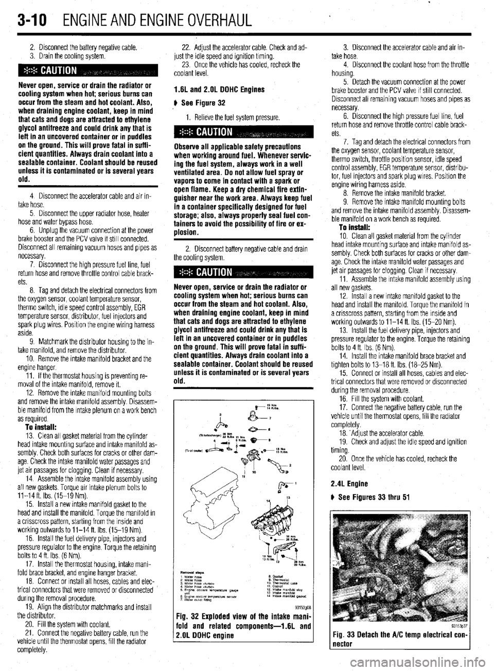
Fig. 32 Exploded view of the intake mani-
fold and related components-1.6L and
2.OL DDHC engine
3. Disconnect the accelerator cable and air in-
take hose.
4. Disconnect the coolant hose from the throttle
housing.
5. Detach the vacuum connection at the power
brake booster and the PCV valve If still connected.
Disconnect all remaining vacuum hoses and pipes as
necessary.
6. Drsconnect the high pressure fuel line, fuel
return hose and remove throttle control cable brack-
ets
7. Tag and detach the electrical connectors from
the oxygen sensor, coolant temperature sensor,
therm0 switch, throttle position sensor, rdle speed
control assembly, EGR temperature sensor, distribu-
tor, fuel injectors and spark plug wires. Position the
engine wiring harness aside.
8. Remove the intake manifold bracket.
9. Remove the intake mamfold mounting bolts
and remove the intake manifold assembly. Disassem-
ble manifold on a work bench as required.
To install:
10. Clean all gasket material from the cylinder
head intake mounting surface and intake manifold as-
sembly. Check both surfaces for cracks or other dam-
age. Check the intake manifold water passages and
jet air passages for clogging. Clean if necessary.
11. Assemble the Intake manifold assembly using
all new gaskets.
12. Install a new intake manifold gasket to the
head and install the manifold. Torque the manifold in
a crisscross pattern, starting from the inside and
working outwards to 11-14 ft. Ibs. (15-20 Nm).
13. Install the fuel delivery pipe, injectors and
pressure regulator to the engine. Torque the retaining
bolts to 4 ft. Ibs. (6 Nm).
14. Install the intake manifold brace bracket and
tighten bolts to 13-18 ft. Ibs. (18-25 Nm).
15. Connect or install all hoses, cables and elec-
trical connectors that were removed or disconnected
during the removal procedure.
16. Fill the system with coolant.
17. Connect the negative battery cable, run the
vehicle until the thermostat opens, fill the radiator
completely.
18. ‘Adjust the accelerator cable.
19. Check and adjust the idle speed and ignition
timing.
20. Once the vehicle has cooled, recheck the
coolant level.
2.4L Engine
) See Figures 33 thru 51
93153p37 Fig. 33 Detach the A/C temp electrical con- 1
Page 73 of 408
.
3-12 ENGINEANDENGINEOVERHAUL
93153p54
1
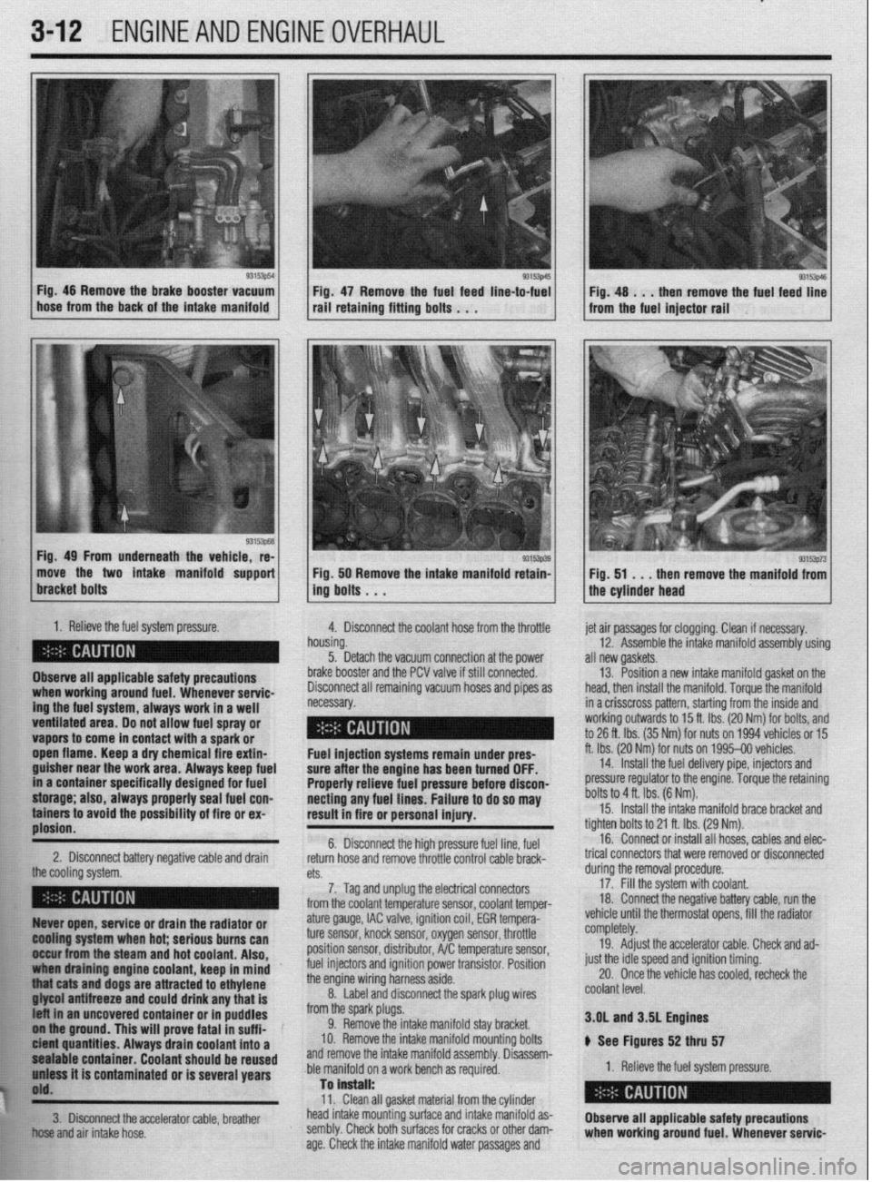
L Fig. 46 Remove the brake booster vacuum
hose from the back of the intake manifold Fig 47 Remove the fuel feed line-to-fuel rail’retaini”g fitti”g bo,ts . . .
Fig. 49 From underneath the vehicle, re-
move the two intake manifold support
1. Relieve the fuel system pressure.
4. Disconnect the coolant hose from the throttle
Observe all applicable safety precautions
ing the fuel system, always work in a well when working around fuel. Whenever servic-
ventilated area. Do not allow fuel spray or - __.
vapors to come in contact with a spark or
._
open flame. Keep a dry chemical fire extin-
guisher near the work area. Always keep fuel
in a container specifically designed for fuel
storage; also, always properly seal fuel con-
tainers to avoid the possibility of fire or ex-
plosion.
2. Disconnect battery negative cable and drain
the cooling rtfctnm 93153p39 Fig. 50 Remove the intake manifold retain-
ing bolts . . .
h
n ousing.
5. Detach the vacuum connection at the power
b
rake booster and the PCV valve if still connected.
C lisconnect all remaining vacuum hoses and pipes as
ecessary. et air passages for clogging. Clean if necessary.
12. Assemble the intake manifold assembly using
III new gaskets.
13. Position a new intake manifold gasket on the
lead, then install the manifold. Torque the manifold
n a crisscross pattern, starting from the inside and
vorking outwards to 15 ft. Ibs. (20 Nm) for bolts, and
o 26 ft. Ibs. (35 Nm) for nuts on 1994 vehicles or 15
t. Ibs. (20 Nr$ for nuts on 1995-00 vehicles.
14. Install the fuel delivery pipe, injectors and
xessure regulator to the engine. Torque the retaining
)olts to 4 ft. Ibs. (6 Nm). Fuel injection systems remain under pres- f
sure after the engine has been turned OFF.
Properly relieve fuel pressure before discon-
necting any fuel lines. Failure to do so may [
result in fire or personal injury.
t 6. Disconnect the high pressure fuel line, fuel
return hose and remove throttle control cable brack- t
n+C.
cm. durino the removal orocedure. 15. Install the intake manifold brace bracket and
ighten bolts to 21 ft. Ibs. (29 Nm).
16. Connect or install all hoses, cables and elec-
rical connectors that were removed or disconnected
7. Tag and unplug the electrical connectors
from the coolant temperature sensor, coolant temper- 17: Fill the system with coolant.
18 Connect the negative battery cable, run the
, . : .., ,, ., , ,
,,,, ,. ,.
93153p73 Fig. 51 . . .
then remove the manifold from
the cylinder head
Ruver open, service or drain the radiator or
@Ming system when hot; serious burns can
II&ur from the steam and hot coolant. Also,
draining engine coolant, keep in mind ’
j “thiat cats and dogs are attracted to ethylene
. . . ..____ “..” 11_,1 -...... any that is
t uncovered container or in puddles
FE ol iha ground. This will prove fatal in suff i-
k ici?M quantities. Always drain coolant into a
$1 pealable container. Coolant should be reused
h’ uniass it is contaminated or is several years
j$O'd.
**w
ature gauge, IAC valve, ignition coil, EGR tempera-
ture sensor, knock sensor, oxygen sensor, throttle
position sensor, distributor, A/C temperature sensor,
fuel injectors and ignition power transistor. Position
the engine wiring harness aside.
8. Label and disconnect the spark plug wires
from the spark plugs.
9. Remove the intake manifold stay bracket.
IO. Remove the intake manifold mounting bolts
and remove the intake manifold assembly. Disassem-
ble manifold on a work bench as required.
Tan is”.+..ll. vemcle unrn me mermosrar opens, ml tne raalaror
completely.
19. Adjust the accelerator cable. Check and ad-
just the idle speed and ignition timing.
20. Once the vehicle has cooled, recheck the
coolant level.
3.OL and 3SL Engines
ti See Figures 52 thru 57
1. Relieve the fuel system pressure.
W.>. Clean all gasket material from the cylinder
!&S head intake mounting surface and intake manifold as-
fir!: 3. Disconnect the accelerator cable, breather
Observe all applicable safety precautions
El .;,
+w..” and air intake hose. sembly. Check both surfaces for cracks or other dam-
age. Check the intake manifold water passages and when working around fuel. Whenever servic-