1900 MITSUBISHI DIAMANTE engine coolant
[x] Cancel search: engine coolantPage 144 of 408
EMISSION CONTROLS 4-2
CRANKCASEVENTILATIONSYSTEM 4-2
OPERATION 4-2
COMPONENTTESTING 4-2
REMOVAL &INSTALLATION 4-2
EVAPORATIVEEMISSIONCONTROLS 4-2
OPERATION 4-2
COMPONENTTESTING 4-3
REMOVAL&INSTALLATION 4-4
EXHAUSTGASRECIRCULATION
SYSTEM 4-5
OPERATION 4-5
COMPONENTTESTING 4-5
REMOVAL&INSTALLATION 4-6
ELECTRONIC ENGINE CONTROLS 4-7
ENGlNECONTROLUNIT/POWERTRAIN
CONTROLMODULE(ECU/PCM) 4-7
OPERATION 4-7
REMOVAL&INSTALLATION 4-7
OXYGENSENSOR 4-8
OPERATION 4-8
TESTING 4-8
REMOVAL&INSTALLATION 4-8
IDLEAIRCONTROLMOTOR 4-9
OPERATION 4-9
TESTING 4-9
REMOVAL&INSTALLATION 4-9
ENGINECOOLANTTEMPERATURE
SENSOR 4-10
OPERATION 4-10
TESTING 4-10
REMOVAL&INSTALLATION 4-10
INTAKEAIRTEMPERATURESENSOR 4-10
OPERATION 4-10
TESTING 4-11
REMOVAL&INSTALLATION 4-11
MASSAIRFLOWSENSOR 4-11
OPERATION 4-11
TESTING 4-11
REMOVAL&INSTALLATION 4-11
MANIFOLDABSOLUTEPRESSURE
SENSOR 4-12
OPERATION 4-12
TESTING 4-12
REMOVAL&INSTALLATION 4-13
THROTTLEPOSITIONSENSOR 4-13
OPERATION 4-13
TESTING 4-13
REMOVAL&INSTALLATION 4-13
CAMSHAFT POSITIONSENSOR 4-14
OPERATION 4-14
TESTING 4-14
REMOVAL&INSTALLATION 4-14
CRANKSHAFTPOSlTlONSENSOR/CRANK
ANGLE SENSOR 4-14
OPERATION 4-14 I
TESTING 4-15 REMOVAL&INSTALLATION 4-15
COMPONENT LOCATIONS 4-16
OBD-1 TROUBLE CODES 4-26
GENERALINFORMATION 4-26
CHECKENGINVMALFUNCTION
INDICATOR LIGHT 4-26
SERVICEPRECAUTIONS 4-26
READING CODES 4-26
WITHASCANTOOL 4-26
WITHOUTASCANTOOL 4-27
CLEARINGCODES 4-27
DIAGNOSTICTROUBLECODES 4-27
OBD-II TROUBLE CODES 4-27
GENERALINFORMATION 4-27
READING CODES 4-27
WITHASCANTOOL 4-27
WITHOUTASCANTOOL 4-27
CLEARINGCODES 4-28
WITHASCANTOOL 4-28
WITHOUTASCANTOOL 4-28
DIAGNOSTICTROUBLECODES 4-28
FLASH OUTCODELIST 4-32
VACUUM DIAGRAMS 4-36
Page 146 of 408
DRIVEABILITYAND EMISSIONS CONTROLS 4-3
895?4Q3:
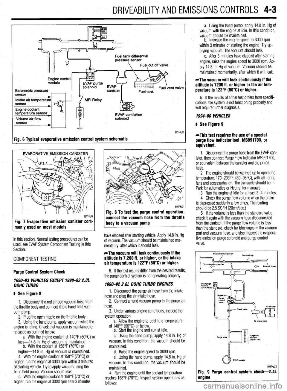
Fig. 6 Tvoical evaoorative emission control system schematic
EVAPORATIVE EMISSION CANISTER
Fig. 7 Evaporative emission canister com-
monly used on most models
in this section. Normal testing procedures can be
used, see EVAP System Component Testing in this
Section.
COMPONENTTESTING
89574g21 Fig. 8 To test the purge control operation,
connect the vacuum hose from the throttle
body to a vacuum pump
have elapsed after starting vehicle. Apply 14.8 in. Hg
of vacuum. The vacuum should be maintained mo-
mentarily, after which it should leak.
*The vacuum will leak continuously if the
altitude is 7,200 ft. or higher, or the intake
air temperature is 122°F (50°C) or higher.
Purge Control System Check
lB!M-93 VEHKLES EXCEPT 39911-92 2.UL
DDHC TURBO
p See Figure 8
1. Disconnect the red striped vacuum hose from
the throttle body and connect it to a hand held vac-
uum pump.
2. Plug the open nipple on the throttle body.
3. Using the hand pump, apply vacuum while the
engine is idling. Check that vacuum is maintained or
released as outlined below:
a. With the enaine coolant at 140°F f6O”C) or
less-14.8 in Hgof vacuum IS maintained. ’
b. With the coolant at 158°F (70°C) or
higher-14.8 in. Hg of vacuum is maintained.
4. With the engine coolant at 158°F (70°C) or
higher, run the engine at 3000 rpm within 3 minutes
of starting vehicle. Try to apply vacuum using the
hand held pump. Vacuum should leak.
5. With the engine coolant at 158°F (70°C) or
higher, run the engine at 3000 rpm after 3 minutes 6. If the test results differ from the desired results,
the purge control system is not operating properly.
199042 2.OL DDHC TURBO ENGINES
1, Disconnect the purge air hose from the intake
hose and plug the air intake hose.
2. Connect a hand vacuum pump to the purge air
hose.
3. Under various engine condrtions, inspect the
system operation:
a. Allow the engine to cool to a temperature
of 140°F (60°C) or below.
b. Start the engine and run at idle.
c. Using the hand pump, apply 14.8 in. Hg of
vacuum. In this condition, the vacuum should be
maintained.
d. Raise the engine speed to 3000 rpm.
e. Using the hand pump, apply 14.8 in. Hg of
vacuum. In this condition, the vacuum should be
maintained.
4. Run the engine until the coolant temperature
reaches 158°F (70°C). Inspect system operations as
follows: a. Using the hand pump, apply 14.8 in. Hg of
vacuum with the engine at idle. In this condition,
vacuum should be maintained.
b. Increase the enaine soeed to 3000 rpm
within 3 minutes of st&ting’the engine. Try ap-
plying vacuum. The vacuum should leak.
c. After 3 minutes have elapsed after starting
engine, raise the engine speed to 3000 rpm. Ap-
ply 14.8 in. Hg of vacuum. Vacuum should be
maintained momentarily, after which it will leak.
*The vacuum will leak continuously if the
altitude is 7200 ft. or higher or the air tem-
perature is 122°F (50°C) or higher.
5. If the results of either test differs from specifi-
cations, the system is not functioning
will require further diagnosis. properly and
1994-00 VEHICLES
p See Figure 9
*This test requires the use of a special
purge flow indicator tool, M8991700, or
equivalent.
1. Disconnect the purge hose from the EVAP can-
ister, then connect Purge Flow Indicator MB991700,
or equivalent between the canister and the purge
hose.
2. The engine should be warmed up to operating
temperature, 170-203°F. (80-95X), with all Irghts,
fans and accessories off. The transaxle should be in
Park for automatics or Neutral for manuals.
3. Run the engine at idle for at least 3-4 minutes.
4. Check the purge flow volume when the brake
is depressed suddenly a few times. The reading
should be 2.5 SCFH (20cmlsec.)
5. If the volume is less than the standard value,
check it again with the vacuum hose disconnected
from the canister. If the purge flow volume is less
than the standard, check for blockages in the vacuum
port and vacuum hose, and also inspect the evapora-
tive emission purge solenord and purge control
valve.
Page 148 of 408
,
DRIVEABILITYAND EMISSIONS CONTROLS 4-5
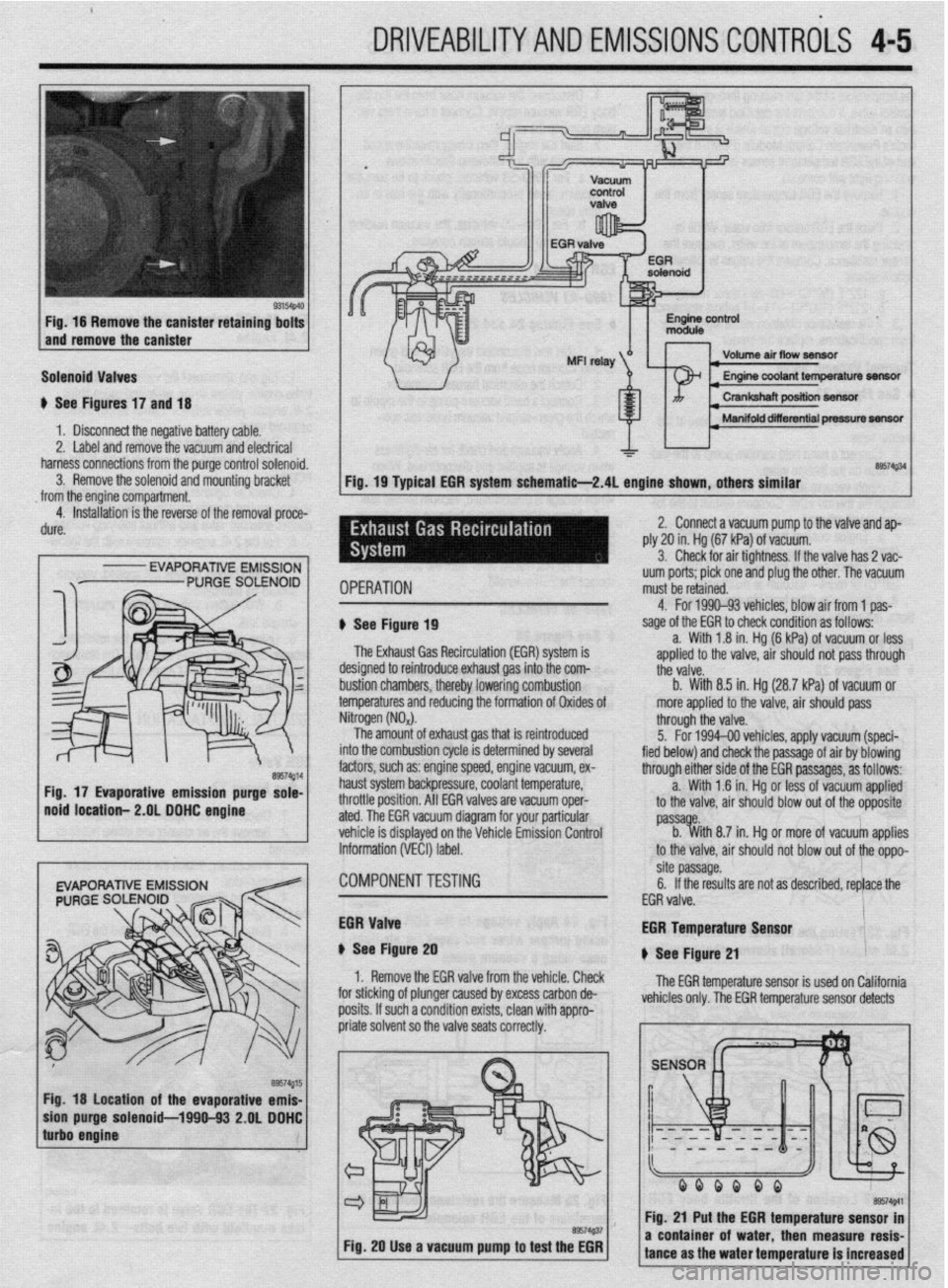
Fig. 16 Remove the canister retaining bolts
and remove the canister
Solenoid Valves
u See Figures 17 and 18
1 b Disconnect the negative battery cable.
2. Label and remove the vacuum and electrical
harness connections from the purge control solenoid.
3. Remove the solenoid and mounting bracket
from the engine compartment.
4. Installation is the reverse of the removal proce-
dure.
I
- EVAPORATIVE EMISSION
Fig. 18 location of the evaporative emis-
purge solenoid-1990-93 2.OL DDHC
Volume air flow seneftr I
I Manifold diierential pressure m
&a$34
Fig. 19 Typical EGR system schematie-2.4L engine shown, others similar
IPERATION uum ports; pick one and plug the other. The vacuum
must be retained.
1 See Figure 19
The Exhaust Gas Recirculation (EM) system is
lesigned to reintroduce exhaust gas into the com-
ttii valve.
rustion chambers, thereby lowering combustion b. With 8.5 in. Hg (28.7 kPa) of vacuum or
emperatures and reducing the formation of Oxides of more applied to the valve, air should pass 4. For 1990-93 vehicles. blow air from 1 oas-
sage of the EGR to check condition as foffows--
a. With 1.8 in. Hg (6 kPa) of vacuum or less
aoolied to the valve. air should not oass throuah
litrogen (NO,).
The amount of exhaust gas that is reintroduced
Ito the combustion cycle is determined by several
actors, such as: engine speed, engine vacuum, ex-
raust system backpressure, coolant temperature,
Irottle position. All EGR valves are vacuum oper-
ted. The EGR vacuum diagram for your particular
chicle is displayed on the Vehicle Emission Control
iformation (VECI) label. through the valve.
5. For 1994-00 vehicles, apply vacuum (speci-
fied below) and check the passage of air by blowing
through either side of the EGR passages, as follows:
a. With 1 .?I in. Hg or less of vacuum applied
to the valve, air should blow out of the opposite
passa e.
b. %ith 8.7 in. Hg or more of vacuum applies
to the valve, air should not blow out of the oppo-
:OMPONENTTESTiNG site passage.
6. If the results are not as described, replace the
EGR valve.
iGR Valve
t See Figure 20
1. Remove the EGR valve from the vehicle. Check
I”..““.
:or sticking of plunger caused by excess carbon de-
losits. If such a condition exists, clean with appro- EGR Temperature Lan*nr
u See Figure 21
The EGR temperature sensor is used on California
vehicles only. The EGR temperature sensor detects
Fig. 20 Use a vacuum pump to test the EGR
I I
a coni tance i of water. then measure resis-
I ms the water temperature is increased
Page 153 of 408
4-10 DRIVEABILITYAND EMISSIONS CONTROLS
I
OPERATION
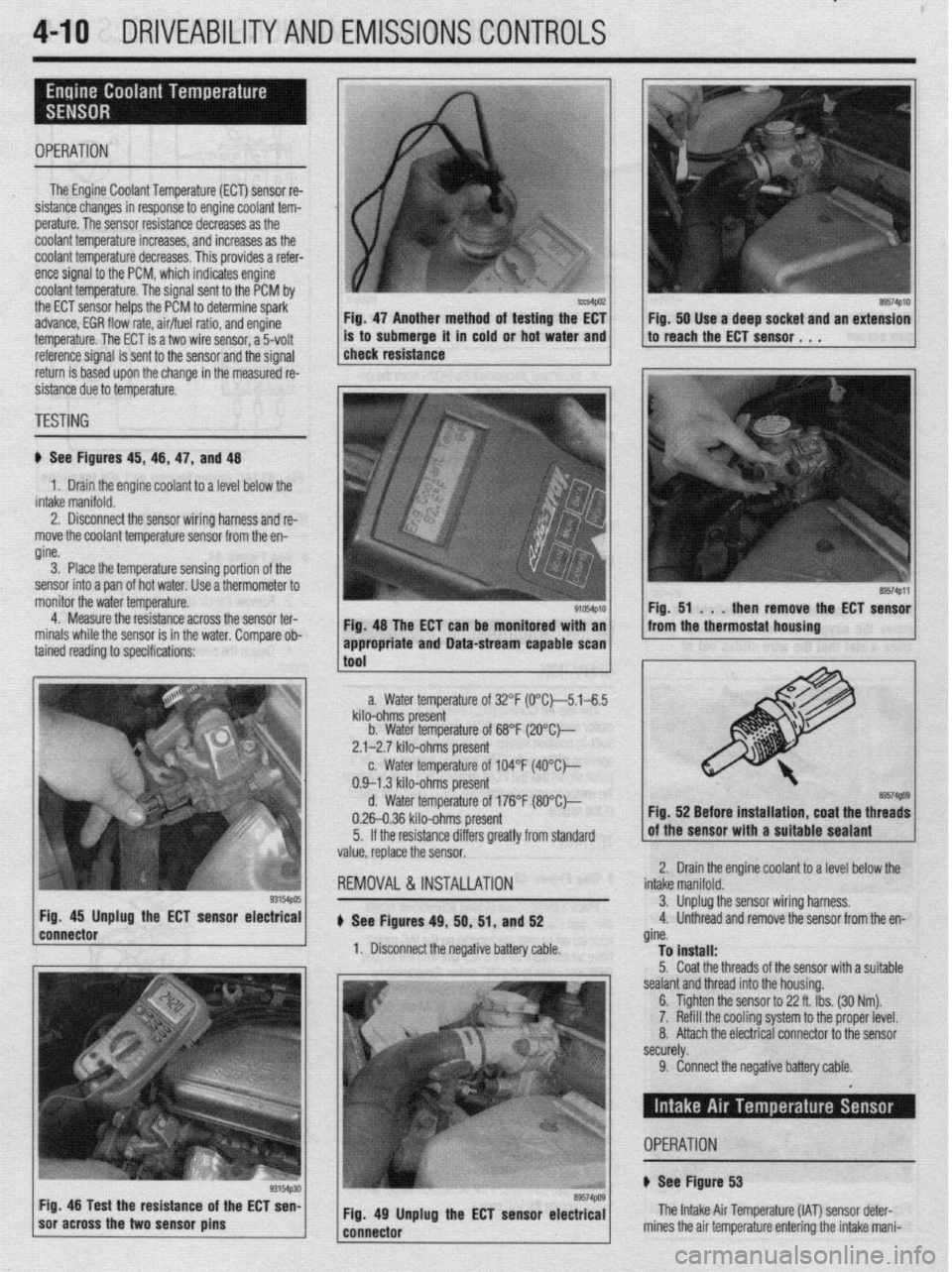
The Engine Coolant Temperature (ECT) sensor re-
sistance changes in response to engine coolant tem-
perature. The sensor resistance decreases as the
coolant temperature increases, and increases as the
coolant temperature decreases. This provides a refer-
ence signal to the PCM, which indicates engine
coolant temperature. The signal sent to the PCM by
the ECT sensor helps the PCM to determine spark-
advance, EGR flow rate, air/fuel ratio, and engine
temperature. The ECT is a two wire sensor, a 5volt
3. Place the temperature sensing portion of the
sensor into a pan of hot water. Use a thermometer to
monitor the water temperature.
4. Measure the resistance across the sensor ter-
minals while the sensor is in the water. Comoare ob- Fig. 47 Another method of testing the EC1 Fig. 50 Use a deep socket and an extension
is to submerge it in cold or hot water and to reach the ECT sensor. 1 ,
reference signal is sent to the sensor and the signal
return is based upon the change in the measured re-
sistance due to temperature. 1 check resistance
TESTING
ti See Figures 45, 46, 47, and 48
1. Drain the engine coolant to a level below the
intake manifold.
2. Disconnect the sensor wiring harness and re-
move the coolant temperature sensor from the en-
gine.
Fig. 48 The ECT can be monitored with an
tained reading to specifications: ’
93154pos Fig. 45 Unplug the ECT sensor electrical
connector
1 soracross the two sensor pins g3154p30 Fig 48 Test the resistance of the ECT sen-
89574PlO
89574Pll
Fig. 51 . . .
then remove the ECT sensor
from the thermostat housing
a. Water temperature of 32°F (0°C~5.1-6.5
kilo-ohms present
b. Water temperature of 68°F (2O”C)--
2.1-2.7 kilo-ohms present
c. Water temperature of 104°F (4O”C)---
0.9-l .3 kilo-ohms present
d. Water temperature of 176°F (8O”Ck,
0.26-0.36 kilo-ohms present
5. If the resistance differs greatly from standard
value, replace the sensor.
REMOVAL &INSTALLATION
u See Figures 49, 50, 51, and 52
1. Disconnect the negative battery cable. Fig. 52 Before installation, coat the threads
Iolant to a level below the 2. Drain the engine c(
intake manifold.
3. Unplug1 the sensor wiring harness,
4. Unthreac
d and remove the sensor from the en-
gine.
To install:
5. Coat the threads of the sensor with a suitable
sealant and thread into the housing.
6. Tighten the sensor to 22 ft. Ibs. (30 Nm).
7. Refill the cooling system to the proper level.
8. Attach the electrical connector to the sensor
securely. appropriate and Data-stream capable scan 1
1
tnnl
9. Connect the negative battery cable.
Fig. 49 Unplug the ECT sensor electrical
---..^-s-- The Intake Air Temperature (IAT) sensor det
mines the air temnerature enterinn the! intake n er-
- ._ r_ -.-._ _. ._. J . _ ..-. ._
iani- OPERATION
+ See Figure 53
Page 159 of 408
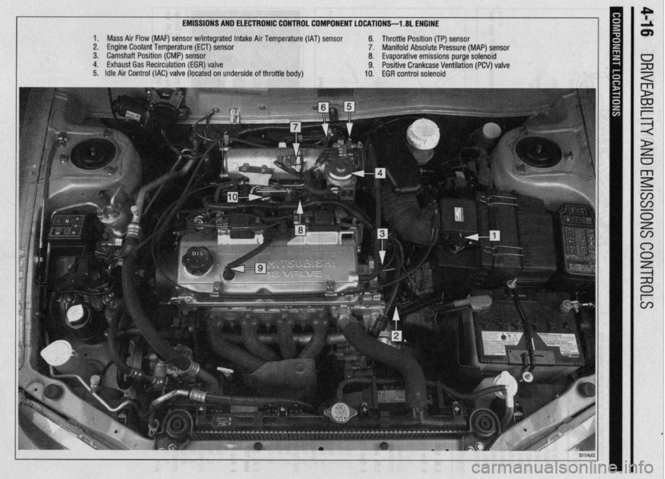
EMISSIONS AND ELECTRONIC CONTROL COMPONENT LOCATIONS-l .8L ENGINE
1. Mass Air Flow (MAF) sensor w/integrated Intake Air Temperature (IAT) sensor 6. Throttle Position (TP) sensor
2. Engine Coolant Temperature (ECT) sensor 7. Manifold Absolute Pressure (MAP) sensor
3. Camshaft Position (CMP) sensor 8. Evaporative emissions purge solenoid
4. Exhaust Gas Recirculation (EGR) valve 9. Positive Crankcase Ventilation (PCV) valve
5. Idle Air Control (IAC) valve (located on underside of throttle body) 10. EGR control solenoid
Page 160 of 408
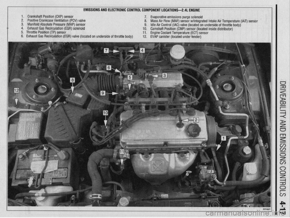
EMISSIONS AND ELECTRONIC CONTROL COMPONENT LOCATIONS-2.4L ENGINE
1. Crankshaft Position (CKP) sensor
7. Evaporative emissions purge solenoid
2. Positive Crankcase Ventilation (PCV) valve
8. Mass Air Flow (MAF) sensor w/integrated Intake Air Temperature (IAT) sensor
3. Manifold Absolute Pressure (MAP) sensor
9. Idle Air Control (IAC) valve (located on underside of throttle body)
4. Exhaust Gas Recirculation (EGR) solenoid
10. Camshaft Position (CMP) sensor (located inside distributor)
5. Throttle Position (TP) sensor
~11. Engine Coolant Temperature (ECT) sensor
6. Exhaust Gas Recirculation (EGR) valve (located on underside of throttle body)
12. EVAP canister (located under fender)
Page 161 of 408
.
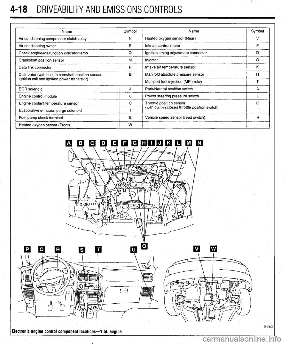
4-18 DRIVEABILITYAND EMISSIONS CONTROLS
Name ; Symbol Name j Symbol
I
Arr conditioning compressor clutch relay ; N Heated oxygen sensor (Rear)
j ”
Air condrtioning swatch , s 1 Idle air control motor
/ F
/
Check engrne/Malfunction Indicator lamp
/ Q lgnrtion trmrng adjustment connector
j D
Crankshaft position sensor / M Injector
! O
Data link connector
j p Intake air temperature sensor / K
Distributor (wrth bulk-in camshaft position sensor, , B Manifold absolute pressure sensor
ignition coil and rgnrtron power transistor) I 1 H
Multrport fuel in]ectron (MFI) relay
i T
EGR solenord
i J PaWNeutral positron switch j A
Engine control module
I u I Power steering pressure switch
Engine coolant temperature sensor c / Throttle position sensor
Evaporative emission purge solenoid
I I I (with burl&In closed throttle position switch) / L _
/ G
I
I
- Fuel pump check terminal /
I j E i Vehicle speed sensor (reed switch)
/ R
Heated oxygen sensor (Front)
I w I
i -
Ilectronic engine control component locations-l 51 engine 93154go1
Page 162 of 408
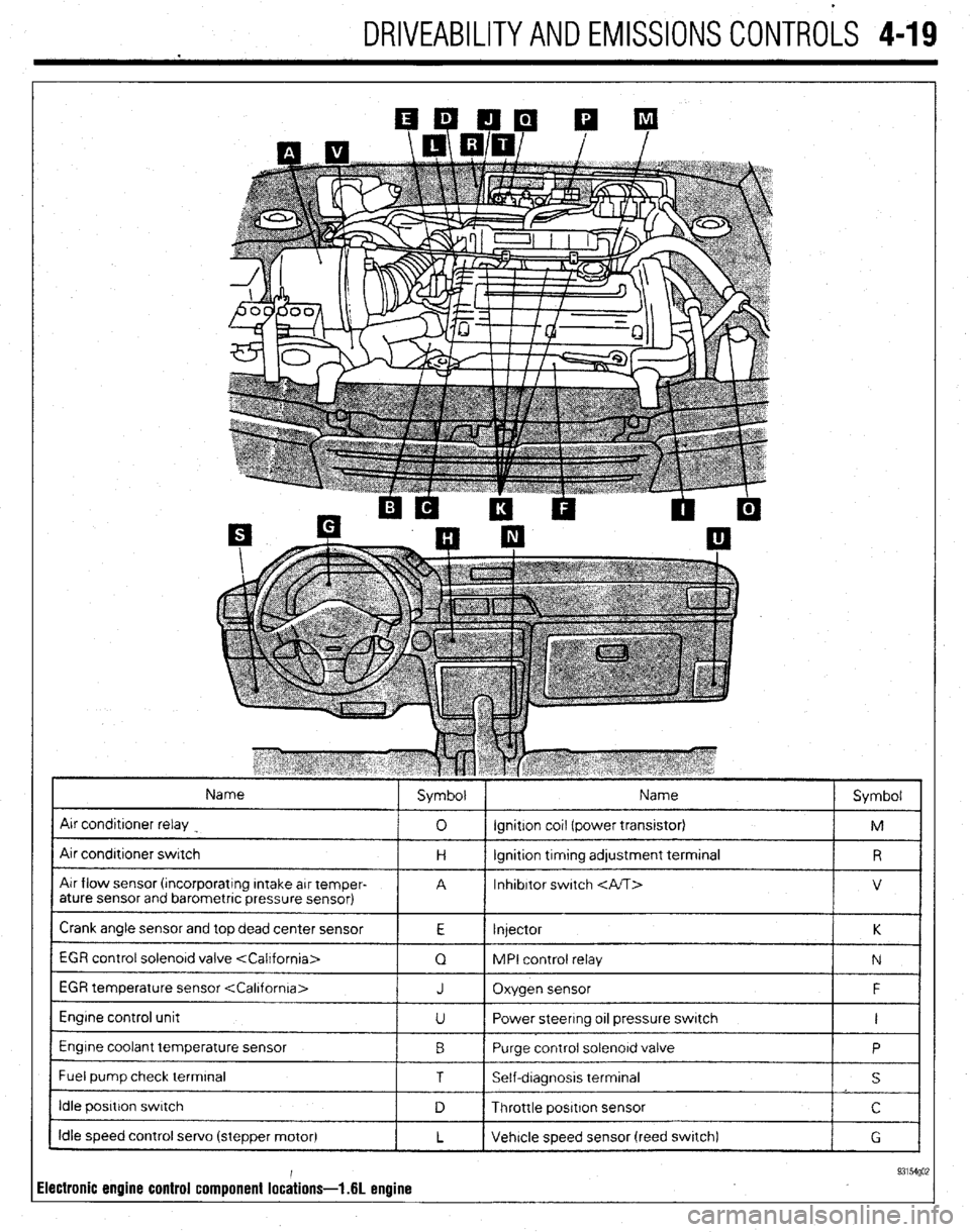
DRIVEABILITYAND EMISSIONS CONTROLS 4-19
Name
Air conditroner relay
Air condrtroner switch
Air flow sensor (rncorporatrng Intake arr temper-
ature sensor and barometric pressure sensor) Symbol Name
Symbol
0 ignition cot1 (power transrstor)
M
H lgnrtion trmtng adjustment terminal
R
A Inhibitor switch
V
Crank angle sensor and top dead center sensor
E Injector K
1 EGR control solenord valve
1 Q 1 MPI control relay
1 N 1
EGR temperature sensor
Engine control unit
Engine coolant temperature sensor
I Fuel pump check terminal J Oxygen sensor F
U Power steering 011 pressure switch I
0 Purge control solenord valve
P
1 T I Self-dragnosis terminal
I s I
I idle posrtron swatch
1 D 1 Throttle positron sensor I c I
Idle speed control servo (stepper motor)
L Vehicle speed sensor (reed swatch)
G
ilectronic engine control component lochions- .6L enuine 93154go;