1900 MITSUBISHI DIAMANTE engine coolant
[x] Cancel search: engine coolantPage 163 of 408
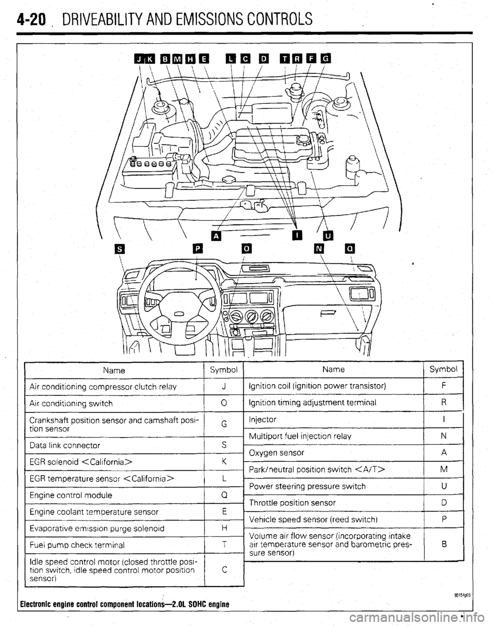
4-20 , DRIVEABILITYAND EMISSIONS CONTROLS
Name Symbol Name Symbol
Air conditioning compressor clutch relay J Ignition coil (ignition power transistor) F
Air conditlonrng switch 0 Ignition trming adjustment terminal R
Crankshaft positron sensor and camshaft posi- Injector I
tion sensor G
~ Multiport fuel injection relay N
Data link connector s ’
- Oxygen sensor A
EGR solenoid
~ Park/neutral positron switch M
EGR temperature sensor
_ Power steering pressure switch
U
Engine control module Q
~ Throttle position sensor
D
Engrne coolant temperature sensor E
Vehicle speed sensor (reed switch) P
Evaporative emrsslon purge solenoid H -
Volume air flow sensor (incorporating intake
Fuel pump check terminal T arr temperature sensor and barometric pres- B
- sure sensor)
Idle speed control motor (closed throttle POW
tron swatch, tdle speed control motor positron
sensor)
! c
93154go: Electronic engine control component locations-2.01 SOHC engine
Page 165 of 408
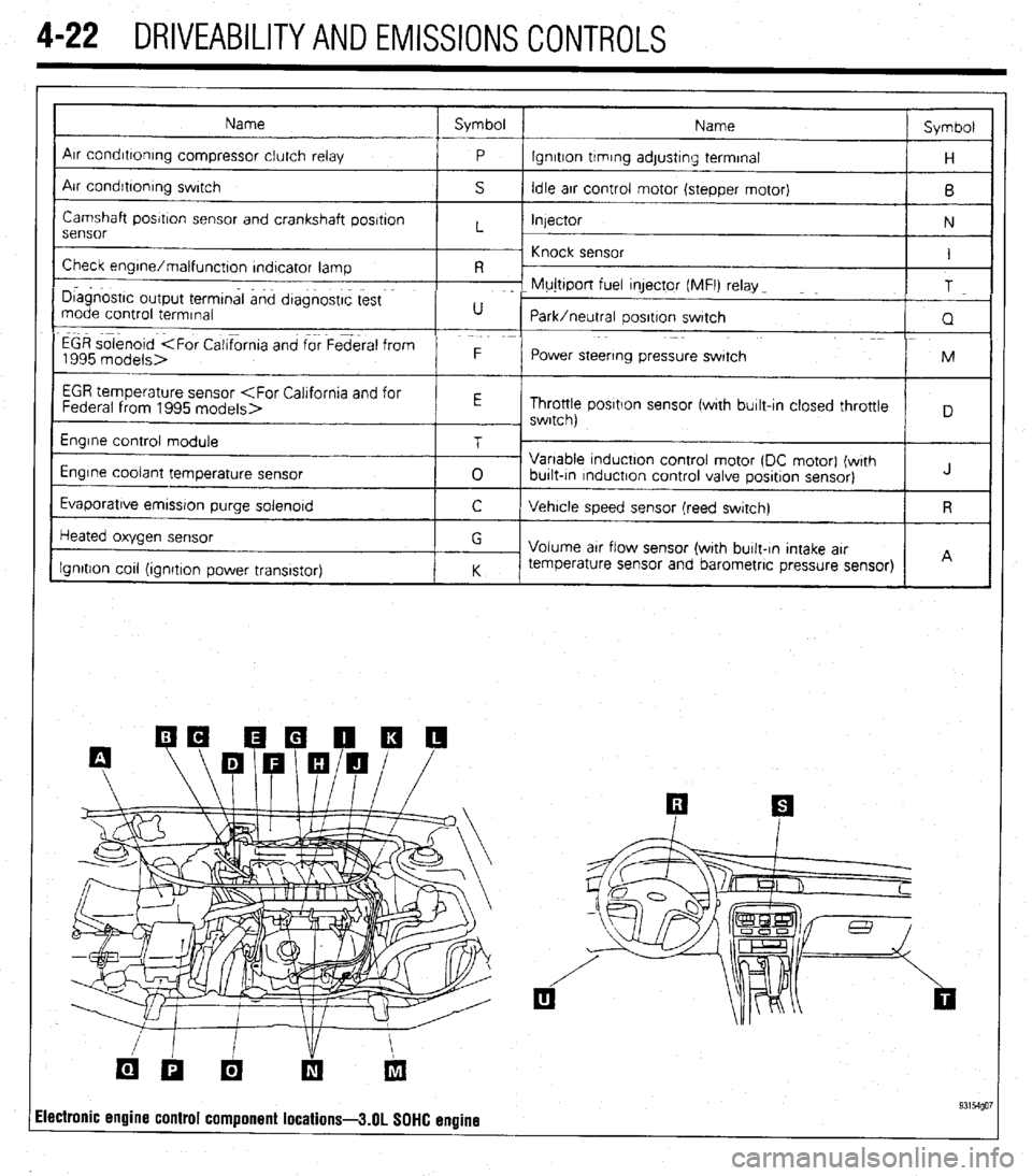
4-22 DRIVEABILITYAND EMISSIONS CONTROLS
Name Symbol
Name Symbol
I
Arr condrttontng compressor clutch relay
P lgnrtton trmrng adjustrng terminal
H
Air condrbonrng swrtch
S Idle arr control motor (stepper motor)
B
Camshaft posrtron sensor and crankshaft posrtron
Injector
N
sensor L
~ Knock sensor
Check engrne/malfunctton rndtcator lamp I
R -
I D~agnostrc output termtnal and dtagnostrc test F- Mujttport fuel qector (MFI) relay _
T
mode control termrnal U
Park/neutral oosrtron swatch
Q
EGR solenoid
1995 models> F
Power steering pressure swatch M
I
EGR temperature sensor
Throttle posrtlon sensor fwrth burlt-In closed throttle
, swrtch)
Engrne control module
Engine coolant temperature sensor
Evaporatrve emrssron purge solenord T
0 Variable tnductton control motor (DC motor) (wrth
burlt-tn rnductron control valve posrtron sensor) J
C Vehrcle speed sensor (reed swatch) R
Heated oxygen sensor
Ignition cot1 (ionrtron Dower transistor) G
Volume arr flow sensor (with burlt-In Intake arr
K temperature sensor and barometric pressure sensor)
I I A
ilectronic engine control component locations-3.01 SOHC engine 93154go7
Page 167 of 408
.
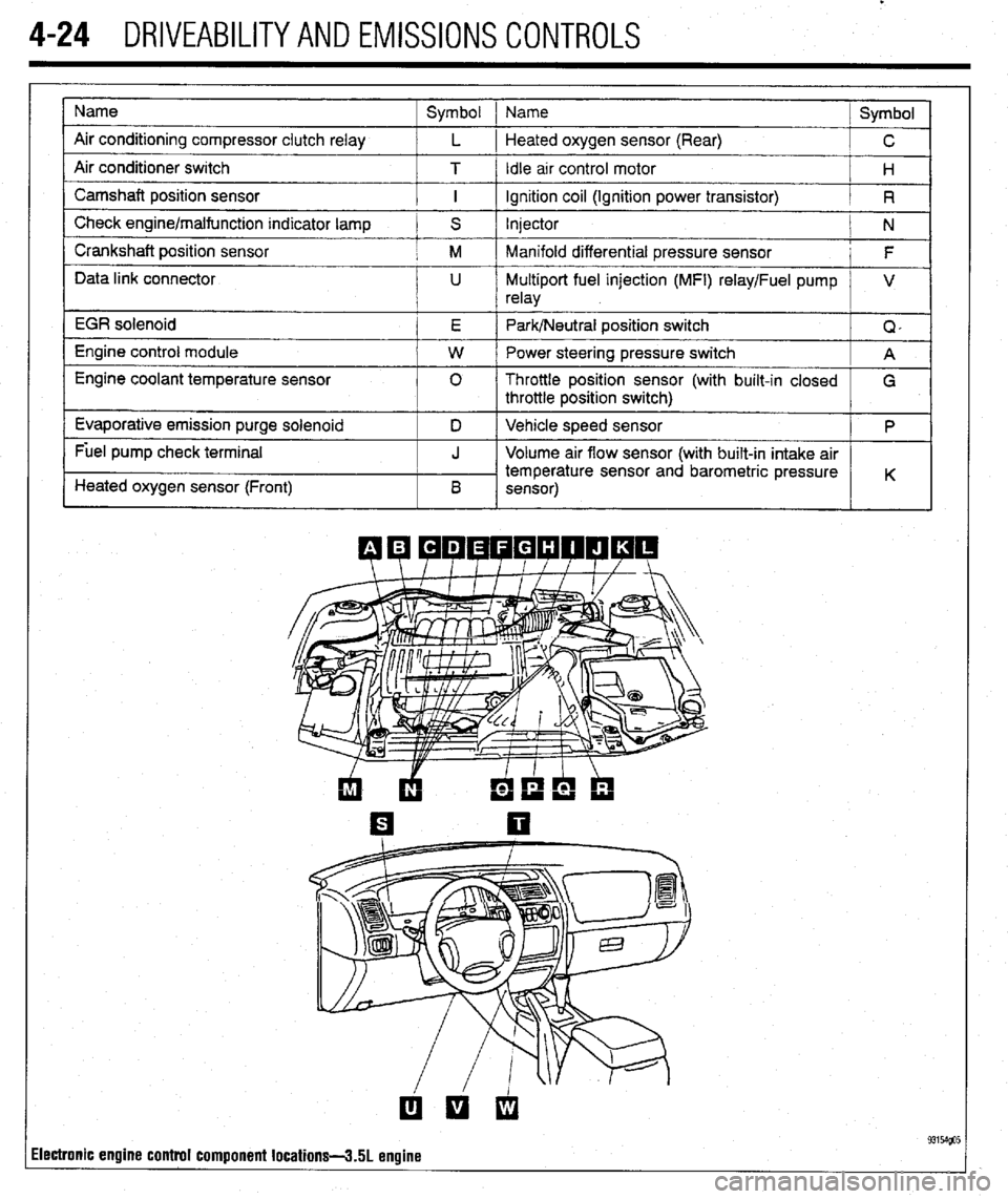
4-24 DRIVEABILITYAND EMISSIONS CONTROLS
Name
Air conditioning compressor clutch relay
Air conditioner switch
Camshaft position sensor
Check engine/malfunction indicator lamp
Crankshaft position sensor
Data link connector
EGR solenoid
Engine control module
Engine coolant temperature sensor
Evaporative emission purge solenoid
Fuel pump check terminal
Heated oxygen sensor (Front) Symbol 1 Name
Symbol
L 1 Heated oxygen sensor (Rear)
C
T / Idle arr control motor
H
I ignition coil (Ignition power transistor)
R
S Injector
N
M Manifold differential pressure sensor
F
U Multiport fuel injection (MFI) relay/Fuel pump V
relay
E Park/Neutral position switch
Q,
W Power steering pressure switch
A
0 Throttle position sensor (with built-in closed
G
throttle position switch)
D Vehicle speed sensor
P
J Volume air flow sensor (with built-in intake air
temperature sensor and barometric pressure
B K
sensor)
ilectronic engine control component locations-3.51 engine
Page 168 of 408
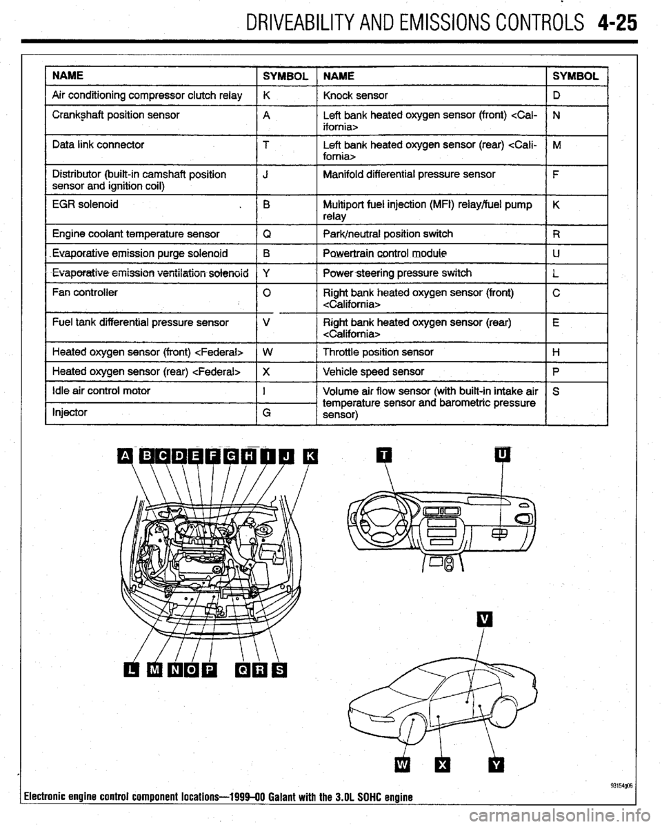
DRIVEABILITYAND EMISSIONS CONTROLS 4-25
NAME
SYMBOL NAME SYMBOL
Air conditioning compressor clutch relay K
Knock sensor D
I Crankshaft position sensor
A Left bank heated oxygen sensor (front)
I I
Data link connector T Left bank heated oxygen sensor (rear)
I Distributor (built-in camshaft position
I J Manifold differential pressure sensor
I F
sensor and ignition coil)
I
EGR solenoid . B Multiport fuel injection (MFI) relay/fuel pump K
relay
1 Engine coolant temperature sensor
IQ 1 Park/neutral position switch IR
Euaporatiue.emission purge solenoid B
Powertraincontrol module LJ
l Evaporatiw5+eiiission ventilation solenoid Y
I Powersteering pressure switch
L
Fan controller 0 Right bank heated oxygen sensor (front) C
Fuel tank differential pressure sensor V Right bank heated oxygen sensor (rear) E
Heated oxygen sensor (front)
I
1 Heated oxygen sensor (rear)
Ip I
Idle air control motor
Injector I
G Volume air flow sensor (with built-in intake air S
temperature sensor and barometric pressure
sensor)
I I
93154@3 lectronic engine control component locations-199940 Galant with the 3.OL SOHC engine
Page 170 of 408
DRIVEABILITYAND EMISSIONS CONTROLS 4-27
WITHOUTASCANTOOL
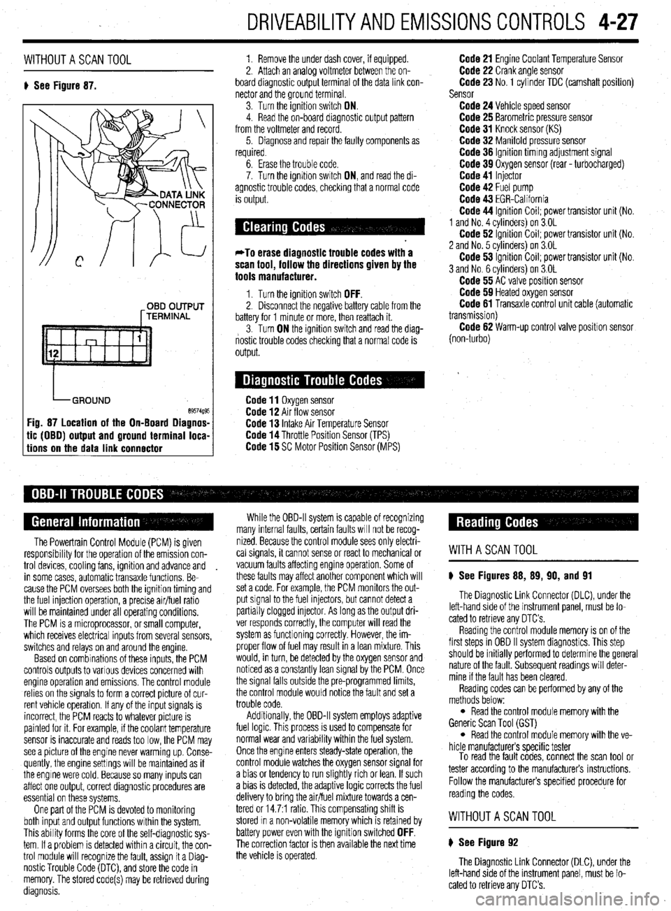
8 See Figure 87. 1. Remove the under dash cover, if equipped.
2. Attach an analoa voltmeter between the on-
board diagnostic outpit terminal of the data link con-
nector and the ground terminal
3. Turn the ignition switch ON.
4. Read the on-board diagnostic output pattern
from the voltmeter and record.
5. Diagnose and repair the faulty components as
required.
OBD OUTPUT
[TERMINAL
tic (OBO) output and ground terminal loca-
tions on the data link connector
6. Erase the trouble code.
7. Turn the ignition swatch ON, and read the di-
agnostic trouble codes, checking that a normal code
is output.
*To erase diagnostic trouble codes with a
scan tool, follow the directions given by the
tools manufacturer.
1. Turn the ignition switch OFF. 2. Disconnect the negative battery cable from the
battery for 1 minute or more, then reattach it.
3. Turn ON the ignition switch and read the diag-
nostic trouble codes checking that a normal code is
output.
Code 11 Oxygen sensor Code 12 Air flow sensor Code 13 Intake Air Temperature Sensor Code 14 Throttle Position Sensor (TPS) Code 15 SC Motor Position Sensor (MPS)
Code 21 Engine Coolant Temperature Sensor Code 22 Crank angle sensor Code 23 No. 1 cylinder TDC (camshaft position)
Sensor
Code 24 Vehicle speed sensor Code 25 Barometric pressure sensor Code 31 Knock sensor (KS) Code 32 Manifold pressure sensor Code 36 Ignition timmg adjustment signal Code 39 Oxygen sensor (rear - turbocharged) Code 41 Injector Code 42 Fuel pump Code 43 EGR-California Code 44 Ignition Coil; power transistor unit (No.
1 and No. 4 cvlinders) on 3.OL
Code 62 ignition Coil; power transistor unit (No.
2 and No. 5 cvlinders) on 3.OL
Code 53 ignition Coil; power transistor unit (No.
3 and No. 6 cylinders) on 3.OL
Code 55 AC valve position sensor Code 59 Heated oxygen sensor Code 61 Transaxle control unit cable (automatic
transmission)
Code 62 Warm-up control valve position sensor
(non-turbo)
The Powertrain Control Module (PCM) is given
responsibrlity for the operation of the emission con-
trol devices, cooling fans, ignition and advance and
in some cases, automatic transaxle functions. Be-
cause the PCM oversees both the ignition timing and
the fuel injection operation, a precise air/fuel ratio
will be maintained under all operating conditions,
The PCM is a microprocessor, or small computer,
which receives electrical inputs from several sensors,
switches and relays on and around the engine.
Based on combinations of these inputs, the PCM
controls outputs to various devices concerned with
engine operation and emissions. The control module
relies on the signals to form a correct picture of cur-
rent vehicle operation. If any of the input signals is
incorrect, the PCM reacts to whatever picture is
painted for it. For example, if the coolant temperature
sensor is inaccurate and reads too low, the PCM may
see a picture of the engine never warming up. Conse-
quently, the engine settings will be maintained as if
the engine were cold. Because so many inputs can
affect one output, correct diagnostic procedures are
essential on these systems,
One part of the PCM is devoted to monitoring
both input and output functions within the system.
This ability forms the core of the self-diagnostic sys-
tem. If a problem is detected within a circuit, the con-
trol module will recognize the fault, assign it a Diag-
nostic Trouble Code (DTC), and store the code in
memory. The stored code(s) may be retrieved during
diagnosis. While the OBD-II system is capable of recognizing
many internal faults, certain faults WIII not be recog-
nized. Because the control module sees only electri-
cal signals, it cannot sense or react to mechanical or
vacuum faults affecting engine operation. Some of
these faults may affect another component which will
set a code. For example, the PCM monitors the out-
put signal to the fuel injectors, but cannot detect a
partially clogged injector. As long as the output dri-
ver responds correctly, the computer will read the
system as functioning correctly. However, the im-
proper flow of fuel may result in a lean mixture. This
would, in turn, be detected by the oxygen sensor and
noticed as a constantly lean signal by the PCM. Once
the signal falls outside the pre-programmed limits,
the control module would notice the fault and set a
trouble code.
Additionally, the OBD-II system employs adaptive
fuel logic. This process is used to compensate for
normal wear and variability within the fuel system.
Once the engine enters steady-state operation, the
control module watches the oxygen sensor signal for
a bias or tendency to run slightly rich or lean. If such
a bias is detected, the adaptive logic corrects the fuel
delivery to bring the air/fuel mixture towards a cen-
tered or 14.7:1 ratio. This compensating shift is
stored In a non-volatile memory which is retained by
battery power even with the ignition switched
OFF. The correction factor is then available the next time
the vehicle is operated.
WITHASCANTOOL
8 See Figures 88, 89, 90, and 91
The Diagnostic Link Connector (DLC), under the
left-hand side of the instrument panel, must be lo-
cated to retrieve any OTC’s
Reading the control module memory is on of the
first steps in OBD II system diagnostics. This step
should be initially performed to determine the general
nature of the fault. Subsequent readings will deter-
mine if the fault has been cleared.
Reading codes can be performed by any of the
methods below:
l Read the control module memory with the
Generic Scan Tool (GST)
l Read the control module memory with the ve-
hicle manufacturers specific tester
To read the fault codes, connect the scan tool or
tester according to the manufacturers instructions.
Follow the manufacturers specified procedure for
reading the codes.
WITHOUTASCANTOOL
8 See Figure 92
The Diagnostic Link Connector (DLC), under the
left-hand side of the instrument panel, must be lo-
cated to retrieve any DTC’s.
Page 172 of 408
DRIVEABILITYAND EMISSIONS CONTROLS 4-29
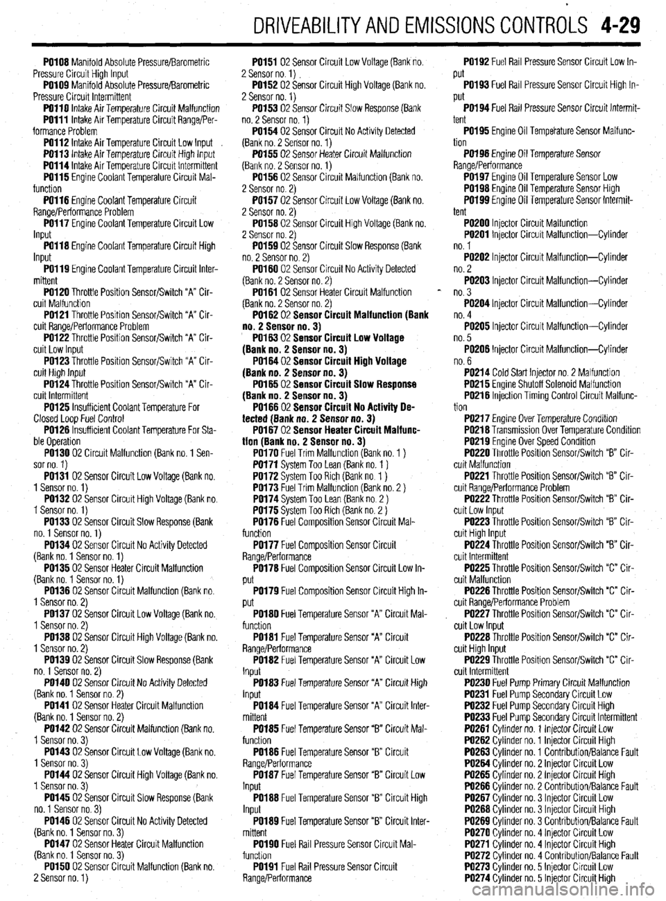
PO108 Manifold Absolute Pressure/Barometric
Pressure Circuit High Input
PO109 Manifold Absolute Pressure/Barometric
Pressure Circuit Intermittent
PO110 intake Air Temperature Circuit Malfunction
PO111 Intake Air Temperature Circuit Range/Per-
formance Problem
PO112 Intake Air Temperature Circuit Low Input
PO113 Intake Air Temoerature Circuit Hiah lnout
PO114 Intake Air Temberature Circuit lnt&miitent
PO115 Engine Coolant Temperature Circuit Mal-
function -
PO116 Engine Coolant Temperature Circuit
Range/Performance Problem
PO117 Engine Coolant Temperature Circuit Low
Input
PO118 Engine Coolant Temperature Circuit High
Input
PO119 Engine Coolant Temperature Circuit Inter-
mittent
PO120 Throttle Position Sensor/Switch “A” Cir-
cuit Malfunction
PO121 Throttle Position Sensor/Switch “A” Cir-
cuit Range/Performance Problem
PO122 Throttle Position Sensor/Switch “A” Cir-
cuit Low Input
PO123 Throttle Position Sensor/Switch “A” Cir-
cuit High Input
PO124 Throttle Position Sensor/Switch “A” Cir-
cuit Intermittent
PO125 Insufficient Coolant Temperature For
Closed Loop Fuel Control
PO126 Insufficient Coolant Temperature For Sta-
ble Operation
PO130 02 Circuit Malfunction (Bank no. 1 Sen-
sor no. 1)
PO131 02 Sensor Circuit Low Voltage (Bank no.
1 Sensor no. 1)
PO132 02 Sensor Circuit High Voltage (Bank no.
1 Sensor no. 1)
PO133 02 Sensor Circuit Slow Response (Bank
no. 1 Sensor no. 1)
PO134 02 Sensor Circuit No Activity Detected
(Bank no. 1 Sensor no. 1)
PO135 02 Sensor Heater Circuit Malfunction
(Bank no. 1 Sensor no. 1)
PO136 02 Sensor Circuit Malfunction (Bank no.
1 Sensor no. 2)
PO137 02 Sensor Circuit Low Voltage (Bank no.
1 Sensor no. 2)
PO138 02 Sensor Circuit High Voltage (Bank no.
1 Sensor no. 2)
PO139 02 Sensor Circuit Slow Response (Bank
no. 1 Sensor no. 2)
PO140 02 Sensor Circuit No Activity Detected
(Bank no. 1 Sensor no. 2)
PO141 02 Sensor Heater Circuit Malfunction
(Bank no. 1 Sensor no. 2)
PO142 02 Sensor Circuit Malfunction (Bank no.
1 Sensor no. 3)
PO143 02 Sensor Circuit Low Voltage (Bank no.
1 Sensor no. 3)
PO144 02 Sensor Circuit High Voltage (Bank no.
1 Sensor no. 3)
PO145 02 Sensor Circuit Slow Response (Bank
no. 1 Sensor no. 3)
PO146 02 Sensor Circuit No Activity Detected
(Bank no. 1 Sensor no. 3)
PO147 02 Sensor Heater Circuit Malfunction
(Bank no. 1 Sensor no. 3)
PO150 02 Sensor Circuit Malfunction (Bank no.
2 Sensor no. 1) PO151 02 Sensor Circuit Low Voltage (Bank no.
2 Sensor no. 1)
PO152 02 Sensor Circuit High Voltage (Bank no.
2 Sensor no. 1)
PO153 02 Sensor Circuit Slow Response (Bank
no. 2 Sensor no. 1)
PO154 02 Sensor Circuit No Activity Detected
(Bank no. 2 Sensor no. 1)
PO155 02 Sensor Heater Circuit Malfunction
(Bank no. 2 Sensor no. 1)
PO156 02 Sensor Circuit Malfunction (Bank no.
2 Sensor no. 2)
PO157 02 Sensor Circuit Low Voltage (Bank no.
2 Sensor no. 2)
PO158 02 Sensor Circuit High Voltage (Bank no.
2 Sensor no. 2)
PO159 02 Sensor Circuit Slow Response (Bank
no. 2 Sensor no. 2)
PO160 02 Sensor Circuit No Activity Detected
(Bank no. 2 Sensor no. 2)
PO161 02 Sensor Heater Circuit Malfunction
(Bank no. 2 Sensor no. 2)
PO162 02 Sensor CircuitMalfunction(8ank
no.2 Sensorno.3)
PO16302 Sensor Circuit Low Voltage
(Bankno. Sensorno.3)
PO16402 Sensor Circuit HighVoltage
(Bankno. Sensorno.3)
PO16502 Sensor Circuit Slow Response
(Bankno. Sensorno.3)
PO166 02 Sensor Circuit No Activity De-
tected(Bankno.2 Sensorno.3)
PO16702 SensorHeaterCircuitMalfunc-
tion(Bank no.2 Sensorno.3)
PO170 Fuel Trim Malfunction (Bank no. 1 )
PO171 System Too Lean (Bank no. 1 )
PO172 Svstem Too Rich (Bank no 1 )
PO173 F;el Trim Malfundtion (Bank io. 2 )
PO174 System Too Lean (Bank no 2 )
PO175 System Too Rich (Bank no. 2 )
PO176 Fuel Composition Sensor Circuit Mal-
function
PO177 Fuel Composition Sensor Circuit
Range/Performance
PO178 Fuel Composition Sensor Circuit Low In-
put
PO179 Fuel Composition Sensor Circuit High In-
put
PO180 Fuel Temperature Sensor “A” Circuit Mal-
function
PO181 Fuel Temperature Sensor “A” Circuit
Range/Performance
PO182 Fuel Temperature Sensor “A” Circuit Low
Input
PO183 Fuel Temperature Sensor “A” Circuit High
Input
PO184 Fuel Temperature Sensor “A” Circuit Inter-
mittent
PO185 Fuel Temperature Sensor “B” Circuit Mal-
function
PO186 Fuel Temperature Sensor “B” Circuit
Range/Performance
PO187 Fuel Temperature Sensor “B” Circuit Low
Input
PO188 Fuel Temperature Sensor “B” Circuit High
Input
PO189 Fuel Temperature Sensor “B” Circuit Inter-
mittent
PO190 Fuel Rail Pressure Sensor Circuit Mal-
funchon
PO191 Fuel Rail Pressure Sensor Circuit
Range/Performance PO192 Fuel Rail Pressure Sensor Circuit Low In-
put
PO193 Fuel Rail Pressure Sensor Circuit High In-
put
PO194 Fuel Rail Pressure Sensor Circuit Intermit-
tent
PO195 Engine Oil Tempetature Sensor Malfunc-
tion
PO198 Engine Oil Temperature Sensor
Range/Performance
PO197 Engine Oil Temperature Sensor Low
PO198 Engine Oil Temperature Sensor High
W199 Engine Oil Temperature Sensor Intermit-
tent
PO200 Injector Circuit Malfunction
PO201 Injector Circuit Malfunction-Cylinder
no. 1
PO202 Injector Circuit Malfunction-Cylinder
no. 2
PO203 Injector Circuit Malfunction-Cylinder
no. 3
PO204 Injector Circuit Malfunction-Cylinder
no. 4
PO205 Injector Circuit Malfunction-Cylinder
no. 5
PO206 Injector Circuit Malfunction-Cylinder
no. 6
PO214 Cold Start Injector no. 2 Malfunction
PO215 Engine Shutoff Solenoid Malfunction
PO218 Injection Timing Control Circuit Malfunc-
tion
PO217 Engine Over Temperature Condition
PO218 Transmission Over Temperature Condition
PO219 Engine Over Speed Condition
PO220 Throttle Position Sensor/Switch ‘9” Cir-
cuit Malfunction
PO221 Throttle Position Sensor/Switch “B” Cir-
cuit Range/Performance Problem
PO222 Throttle Position Sensor/Switch “B” Cir-
cuit Low Input
PO223 Throttle Position Sensor/Switch “B” Cir-
cuit High Input
PO224 Throttle Position Sensor/Switch “B” Cir-
cuit Intermittent
PO225 Throttle Position Sensor/Switch “C” Cir-
cuit Malfunction
PO226 Throttle Position Sensor/Switch “C” Cir-
cuit Range/Performance Problem
PO227 Throttle Position Sensor/Switch “c” Cir-
cuit Low Input
PO228 Throttle Position Sensor/Switch “C” Cir-
cuit High Input
PO229 Throttle Position Sensor/Switch “C” Cir-
cuit Intermittent
PO230 Fuel Pump Primary Circuit Malfunction
PO231 Fuel Pump Secondary Circuit Low
PO232 Fuel Pump Secondary Circuit High
PO233 Fuel Pump Secondary Circuit Intermittent
PO261 Cylinder no. 1 Injector Circuit Low
PO262 Cylinder no. 1 Injector Circuit High
PO263 Cylinder no. 1 Contribution/Balance Fault
PO264 Cvlinder no. 2 lniector Circuit Low
PO265 Cylinder no. 2 Injector Circuit High
PO266 Cylinder no. 2 Contribution/Balance Fault
PO267 Cylinder no. 3 Injector Circuit Low
PO268 Cylinder no. 3 Injector Circuit High
PO269 Cylinder no. 3 Contribution/Balance Fault
PO270 Cylinder no. 4 Injector Circuit Low
PO271 Cvlinder no. 4 lniector Circuit Hiah
PO272 Cylinder no. 4 CbntributionlBalaice Fault
PO273 Cylinder no. 5 Injector Circuit Low
PO274 Cylinder no. 5 Injector Circuit High
Page 213 of 408
640 CHASSIS ELECTRICAL
careful not to allow anything to come in contact with
the air bag unit.
16. Remove the glove box lamp assembly.
17. Remove the remaining instrument panel
mounting screws and remove the instrument panel
from the vehicle.
18. Remove the left side foot shower ductwork,
lap cooler duct and center duct.
19. Remove the front and center reinforcements
and center stay assembly.
20. Remove the air distribution duct assembly.
21. Detach all connectors from heater-box-
mounted items.
22. Remove the heater box mounting screws and
nut, then remove the unit from the vehicle.
23. Disassemble on a workbench. Remove the
heater core from the heater case.
To install:
24. Thoroughly clean and dry the inside of the
case and install the heater core and all related parts.
25. Install the heater unit to the vehicle and install
the mounting screws and nut. Be sure the evaporator
case and heater case are fitted together properly. At-
tach all connectors to heater-box-mounted items.
26. Install the air distribution duct assembly. In-
stall the front and center reinforcements and center
stay assembly.
27. Install the center duct, lap cooler duct and left
side foot shower duct.
28. Install the instrument panel and mounting
screws.
29. Install the glove box lamp assembly.
30. Secure the steering column and attach all
steering column connectors.
31. Install the speedometer cable adapter to the
instrument panel.
32. Install the instrument cluster and the instru-
ment cluster bezel.
33. Install the speakers to the top of the instru-
ment panel.
34. Install the cup holder.
35. Install the climate control system control
head.
36. Install the stereo entertainment system and
bezel.
37. Install the screw below the glove box assem-
bly, and the entire glove box unit.
38. Install the steering column covers.
39. Install the knee protector support bracket, the
protector and the decorative plugs.
40. Install the console and the ashtray. 41. Install the right side foot shower duct.
42. Install the passenger side undercover.
43. Connect the heater hoses to the core tubes.
44. Fill the cooling system.
45. Connect the negative battery cable and check
the entire climate control system for proper operation
and leaks.
Galant
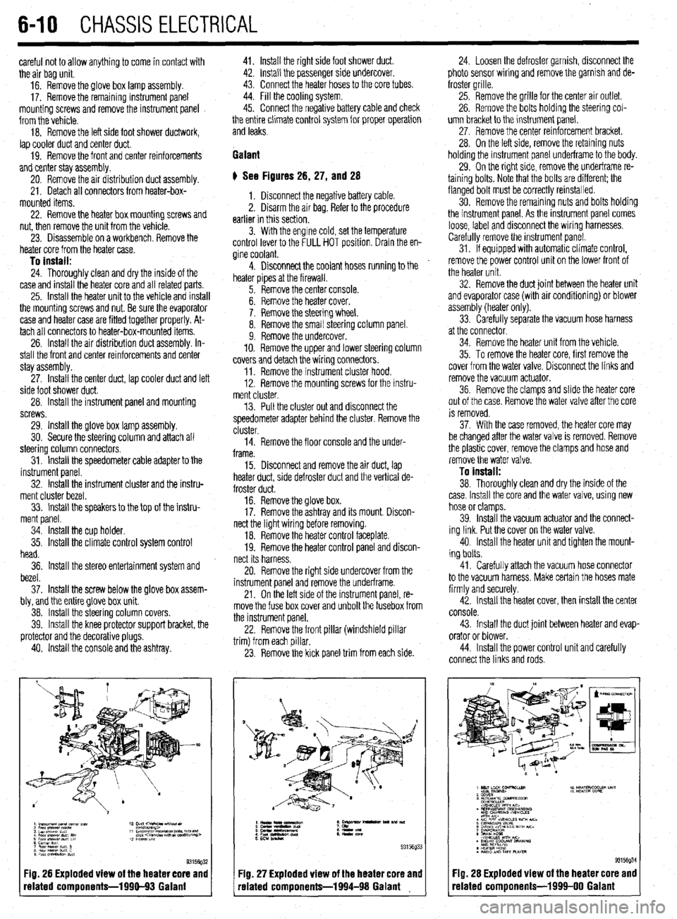
# See Figures 26, 27, and 28
1. Disconnect the negative battery cable.
2. Disarm the air bag. Refer to the procedure
earlier in this section.
3. With the engine cold, set the temperature
control lever to the FULL HOT position. Drain the en-
gine coolant.
4. Disconnect the coolant hoses running to the
heater pipes at the firewall.
5. Remove the center console.
6. Remove the heater cover.
7. Remove the steering wheel.
8. Remove the small steering column panel.
9. Remove the undercover.
10. Remove the upper and lower steering column
covers and detach the wiring connectors.
11. Remove the instrument cluster hood.
12. Remove the mounting screws for the instru-
ment cluster.
13. Pull the cluster out and disconnect the
speedometer adapter behind the cluster. Remove the
cluster.
14. Remove the floor console and the under-
frame.
15. Disconnect and remove the air duct, lap
heater duct, side defroster duct and the vertical de-
froster duct.
16. Remove the glove box.
17. Remove the ashtray and its mount. Discon-
nect the light wiring before removing.
18. Remove the heater control faceplate.
19. Remove the heater control panel and discon-
nect its harness.
20. Remove the right side undercover from the
instrument panel and remove the underframe.
21. On the left side of the instrument panel, re-
move the fuse box cover and unbolt the fusebox from
the instrument panel.
22. Remove the front pillar (windshield pillar
trim) from each pillar.
23. Remove the kick panel trim from each side.
Fig. 26 Exploded view of the heater core and
related components-1990-93 Galant
:IQ. 27 Exploded view of the heater core and
-elated components-1994-98 Galant 24. Loosen the defroster garnish, disconnect the
photo sensor wiring and remove the garnish and de-
froster grille.
25. Remove the grille for the center air outlet.
26. Remove the bolts holding the steering col-
umn bracket to the instrument panel.
27, Remove the center reinforcement bracket.
28. On the left side, remove the retaining nuts
holding the instrument panel underframe to the body.
29. On the right side, remove the underframe re-
taining bolts. Note that the bolts are different; the
flanged bolt must be correctly reinstalled.
30. Remove the remaining nuts and bolts holding
the instrument panel. As the instrument panel comes
loose, label and disconnect the wiring harnesses.
Carefully remove the instrument panel.
31. If equipped with automatic climate control,
remove the power control unit on the lower front of
the heater unit.
32. Remove the duct joint between the heater unit
and evaporator case (with air conditioning) or blower
assembly (heater only).
33. Carefully separate the vacuum hose harness
at the connector.
34. Remove the heater unit from the vehicle.
35. To remove the heater core, first remove the
cover from the water valve. Disconnect the links and
remove the vacuum actuator.
36. Remove the clamps and slide the heater core
out of the case. Remove the water valve after the core
is removed.
37. With the case removed, the heater core may
be changed after the water valve is removed. Remove
the plastic cover, remove the clamps and hose and
remove the water valve.
To install:
38. Thoroughly clean and dry the inside of the
case. Install the core and the water valve, using new
hose or clamps.
39. Install the vacuum actuator and the connect-
ing link. Put the cover on the water valve.
40. Install the heater unit and tighten the mount-
ing bolts.
41. Carefully attach the vacuum hose connector
to the vacuum harness. Make certain the hoses mate
firmly and securely.
42. Install the heater cover, then install the center
console.
43. Install the duct joint between heater and evap-
orator or blower.
44. Install the power control unit and carefully
connect the links and rods.
Fig. 28 Exploded view of the heater core and
related components-1999-00 Galant
Page 384 of 408
11-2 TROUBLESHOOTING
Condition
Section/Item Number
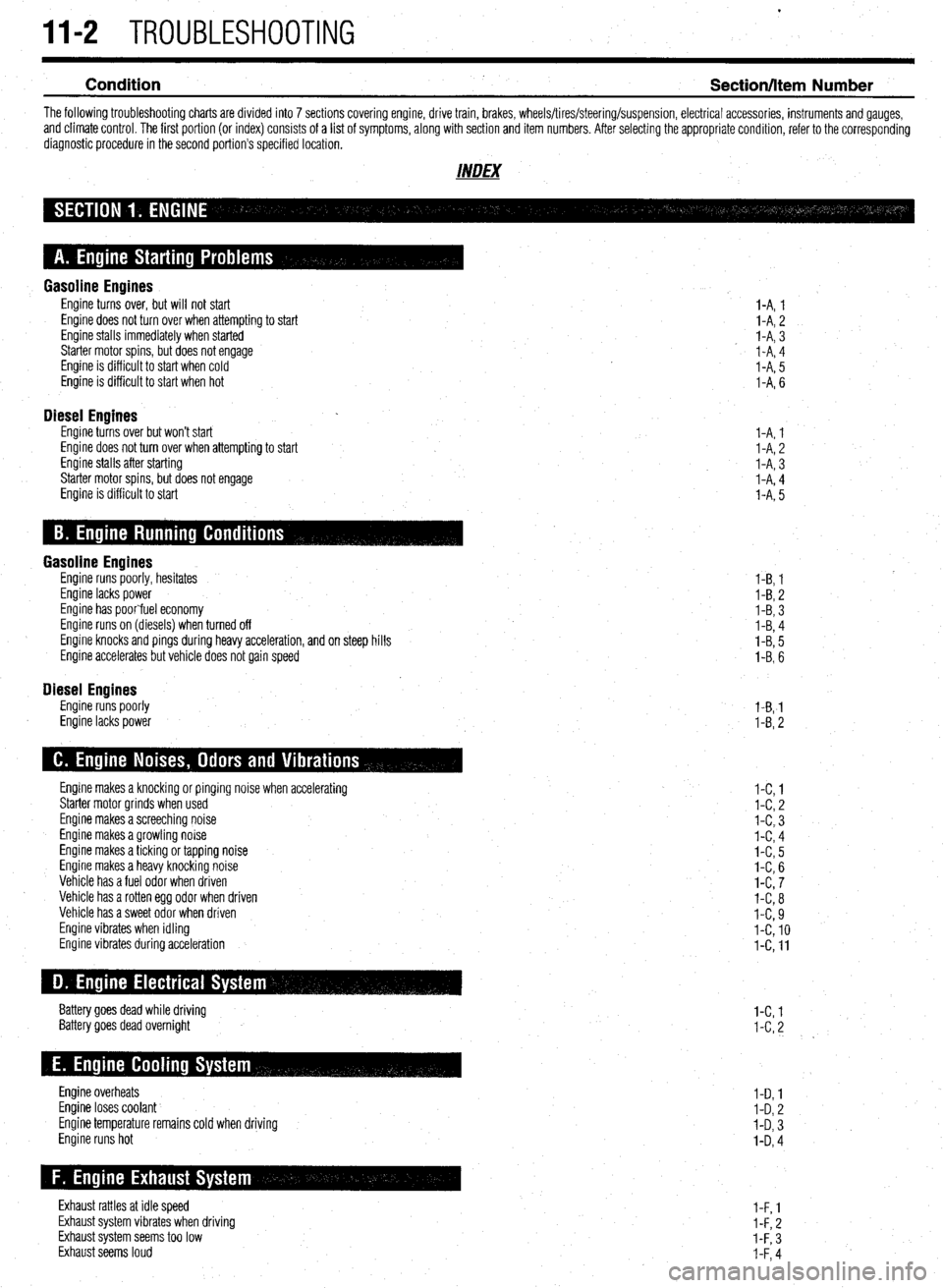
The following troubleshooting charts are divided into 7 sections covering engine, drive train, brakes, wheels/tires/steering/suspension, electrical accessories, instruments and gauges,
and climate control. The first portion (or index) consists of a list of symptoms, along with section and item numbers. After selecting the appropriate condition, refer to the corresponding
diagnostic procedure in the second portion’s specified location.
INDEX
Gasoline Engines Engine turns over, but will not start
Engine does not turn over when attempting to start
Engine stalls immediately when started
Starter motor spins, but does not engage
Engine is difficult to start when cold
Engine is difficult to start when hot
Diesel Engines Engine turns over but won’t start
Engine does not turn over when attempting to start
Engine stalls after starting
Starter motor spins, but does not engage
Engine is difficult to start I-A, 1
l-A, 2
I-A, 3
I-A, 4
I-A, 5
I-A, 6
I-A, 1
l-A, 2
I-A, 3
I-A, 4
l-A, 5
Gasoline Engines Engine runs poorly, hesitates
Engine lacks power
Engine has poorfuel economy
Engine runs on (diesels) when turned off
Engine knocks and pings during heavy acceleration, and on steep hills
Engine accelerates but vehicle does not gain speed
Diesel Engines Engine runs poorly
Engine lacks power l-B, 1
I-B, 2
l-B, 3
I-B, 4
l-B, 5
I-B, 6
l-B,-1
l-B, 2
Engine makes a knocking or pinging noise when accelerating
Starter motor grinds when used
Engine makes a screeching noise
Engine makes a growling noise
Engine makes a ticking or tapping noise
Engine makes a heavy knocking noise
Vehicle has a fuel odor when driven
Vehicle has a rotten egg odor when driven
Vehicle has a sweet odor when driven
Engine vibrates when idling
Engine vibrates during acceleration
Battery goes dead while driving
Battery goes dead overnight
Engine overheats
Engine loses coolant
Engine temperature remains cold when driving
Engine runs hot
Exhaust rattles at idle speed
Exhaust system vibrates when driving
Exhaust system seems too low
Exhaust seems loud l-C, 1
l-C, 2
l-C, 3
I-C, 4
l-C, 5
I-C, 6
l-C, 7
l-C, 8
I-C, 9
I-C, 10
l-C, 11
l-C, 1
I-C, 2
I-D, 1
I-D, 2
I-D, 3
I-D, 4
l-F, 1
l-F, 2
I-F, 3
I-F, 4