Page 89 of 256

STARTING AND OPERATING87
To Activate
Push the on/off button to activate the Cruise Control. The
cruise indicator light in the instrument cluster display will
illuminate. To turn the system off, push the on/off button
a second time. The cruise indicator light will turn off.
The system should be turned off when not in use.
To Set A Desired Speed
Turn the Cruise Control on.
NOTE:The vehicle should be traveling at a steady speed and on
level ground before pushing the SET (+) or SET (-) button.
When the vehicle has reached the desired speed, push
the SET (+) or SET (-) button and release. Release the
accelerator and the vehicle will operate at the selected
speed.
To Vary The Speed Setting
To Increase Or Decrease The Set Speed
When the Cruise Control is set, you can increase speed by
pushing the SET (+) button, or decrease speed by pushing
the SET (-) button. U.S. Speed (mph)
Pushing the SET (+), or SET (-) button once will result in
a 1 mph speed adjustment. Each subsequent tap of
the button results in an adjustment of 1 mph.
If the button is continually pushed, the set speed will
continue to adjust in 5 mph increments until the button
is released. The new set speed is reflected in the instru -
ment cluster display.
Metric Speed (km/h)
Pushing the SET (+), or SET (-) button once will result in
a 1 km/h speed adjustment. Each subsequent tap of
the button results in an adjustment of 1 km/h.
If the button is continually pushed, the set speed will
continue to adjust in 10 km/h increments until the
button is released. The new set speed is reflected in
the instrument cluster display.
To Accelerate For Passing
Press the accelerator as you would normally. When the
pedal is released, the vehicle will return to the set speed.
USING CRUISE CONTROL ON HILLS
The transmission may downshift on hills to maintain the
vehicle set speed.
The Cruise Control system maintains speed up and down
hills. A slight speed change on moderate hills is normal.
On steep hills, a greater speed loss or gain may occur so it
may be preferable to drive without Cruise Control.
To Resume Speed
To resume a previously set speed, push the RES button
and release. Resume can be used at any speed above
20 mph (32 km/h).
To Deactivate
A tap on the brake pedal, pushing the CANC button, or
normal brake pressure will deactivate the Cruise Control
system without erasing the set speed from memory.
Pushing the on/off button or placing the ignition in the OFF
position erases the set speed from memory.
PARKSENSE REAR PARK ASSIST —
IF EQUIPPED
The ParkSense Rear Park Assist system provides visual
and audible indications of the distance between the rear
fascia and a detected obstacle when backing up (e.g.
during a parking maneuver). If your vehicle is equipped
with an automatic transmission, the vehicle brakes may
be automatically applied and released when performing a
reverse parking maneuver if the system detects a possible
collision with an obstacle.
WARNING!
Leaving the Cruise Control system on when not in use is
dangerous. You could accidentally set the system or
cause it to go faster than you want. You could lose
control and have an accident. Always leave the system
off when you are not using it.
WARNING!
Cruise Control can be dangerous where the system
cannot maintain a constant speed. Your vehicle could
go too fast for the conditions, and you could lose control
and have an accident. Do not use Cruise Control in
heavy traffic or on roads that are winding, icy,
snow-covered or slippery.
4
23_RUV_OM_EN_US_t.book Page 87
Page 90 of 256

88STARTING AND OPERATING
NOTE:
The driver can override the automatic braking function
by pressing the gas pedal, turning ParkSense off via
ParkSense switch, or changing the gear while the auto -
matic brakes are being applied.
Automatic brakes will not be available if Electronic
Stability Control (ESC) is not available.
Automatic brakes will not be available if there is a
faulted condition detected with the ParkSense Park
Assist system or the Braking System Module.
The automatic braking function may not provide
enough vehicle deceleration to avoid colliding with a
detected obstacle depending on vehicle speed, road
conditions, and brake capability.
The automatic braking function may not be applied fast
enough for moving obstacles that approach the rear of
the vehicle from the left and/or right sides.
The automatic braking function can be enabled/
disabled from the Customer Programmable Features
section of the Uconnect system.
ParkSense will retain its last known configuration state
for the automatic braking function through ignition
cycles.
The automatic braking function is intended to assist the
driver in avoiding possible collisions with detected
obstacles when backing up in REVERSE gear.
NOTE:
The system is designed to assist the driver and not to
substitute the driver.
The driver must stay in full control of the vehicle's
acceleration and braking and is responsible for
controlling the vehicle's movements.
For limitations of this system and recommendations/
precautions, see
Úpage 91.
ParkSense will retain the last system state (enabled or
disabled) from the last ignition cycle when the ignition is
changed to the ON/RUN position.
ParkSense can be active only when the gear selector is in
REVERSE. If ParkSense is enabled at this gear selector
position, the system will remain active until the vehicle
speed is increased to approximately 7 mph (11 km/h)
or above. When in REVERSE and above the system's
operating speed, a warning will appear within the
instrument cluster display indicating the vehicle speed is
too fast. The system will become active again if the vehicle
speed is decreased to speeds less than approximately
6 mph (9 km/h).
PARKSENSE SENSORS
The four ParkSense sensors, located in the rear
fascia/bumper, monitor the area behind the vehicle that is
within the sensors’ field of view. The sensors can detect
obstacles from approximately 12 inches (30 cm) up to
79 inches (200 cm) from the rear fascia/bumper in the
horizontal direction, depending on the location, type and
orientation of the obstacle.
PARKSENSE WARNING DISPLAY
The ParkSense Warning screen will only be displayed if Sound
and Display is selected from the Customer-Programmable
Features section of the Uconnect system
Ú
page 105.
The ParkSense Warning screen is located within the
instrument cluster display
Úpage 62. It provides visual
warnings to indicate the distance between the rear
fascia/bumper and the detected obstacle.
PARKSENSE DISPLAY
When the vehicle is in REVERSE and an obstacle has been
detected, the warning display will turn on indicating the
system status, and remain on until the vehicle is moved
out of REVERSE.
The system will indicate a detected obstacle by showing a
single arc in one or more regions based on the obstacle’s
distance and location relative to the vehicle.
If an obstacle is detected in the center rear region, the
display will show a single solid arc in the center rear region
and will produce a one-half second tone. As the vehicle
moves closer to the obstacle, the display will show the
single arc moving closer to the vehicle and the tone will
change from slow, to fast, to continuous.
If an obstacle is detected in the left and/or right rear
region, the display will show a single flashing arc in the
left and/or right rear region and will produce a fast tone.
As the vehicle moves closer to the obstacle, the display will
show the single arc moving closer to the vehicle and the
tone will change from fast to continuous.
23_RUV_OM_EN_US_t.book Page 88
Page 91 of 256
STARTING AND OPERATING89
Rear ParkSense Arcs
1 — Continuous Tone/Flashing Arc 4 — Slow Tone/Solid Arc
2 — Fast Tone/Flashing Arc 5 — Slow Tone/Solid Arc
3 — Fast Tone/Flashing Arc 6 — Single 1/2 Second Tone/Solid Arc
4
23_RUV_OM_EN_US_t.book Page 89
Page 92 of 256

90STARTING AND OPERATING
The vehicle is close to the obstacle when the warning display shows one flashing arc and sounds a continuous tone. The following chart shows the warning alert operation when the
system is detecting an obstacle:
NOTE:ParkSense will reduce the volume of the radio, if on, when the system is sounding an audio tone.
WARNING ALERTS
Rear Distance
(inches/cm) Greater than
79 inches (200 cm) 79-59 inches
(200-150 cm) 59-47 inches
(150-120 cm) 47-39 inches
(120-100 cm) 39-25 inches
(100-65 cm) 25-12 inches
(65-30 cm) Less than
12 inches (30 cm)
Arcs — Left NoneNone NoneNoneNone2nd Flashing 1st Flashing
Arcs — Center None6th Solid 5th Solid4th Solid 3rd Flashing 2nd Flashing 1st Flashing
Arcs — Right NoneNone NoneNoneNone2nd Flashing 1st Flashing
Audible Alert Chime None Single 1/2 Second
Tone (for rear center only) Slow (for rear
center only) Slow (for rear
center only) Fast (for rear
center only) Fast
Continuous
Radio Volume Reduced No
Yes YesYesYes YesYes
23_RUV_OM_EN_US_t.book Page 90
Page 93 of 256

ENABLING AND DISABLING PARKSENSE
ParkSense can be enabled and disabled with
the ParkSense switch, located on the switch
panel below the Uconnect display.
When")
STARTING AND OPERATING91
(Continued)
ENABLING AND DISABLING PARKSENSE
ParkSense can be enabled and disabled with
the ParkSense switch, located on the switch
panel below the Uconnect display.
When the ParkSense switch is pushed to disable the system,
the instrument cluster will display the “PARKSENSE OFF”
message for approximately five seconds. When the gear
selector is moved to REVERSE and the system is disabled, the
instrument cluster display will show the “PARKSENSE OFF”
message for as long as the vehicle is in REVERSE.
The ParkSense switch LED will be on when ParkSense is
disabled or requires service. The ParkSense switch LED will
be off when the system is enabled. If the ParkSense switch
is pushed, and requires service, the ParkSense switch LED
will blink momentarily, and then the LED will be on.
SERVICE THE PARKSENSE REAR PARK
A
SSIST SYSTEM
During vehicle start up, when the ParkSense Rear Park Assist
system has detected a faulted condition, the instrument cluster
will actuate a single chime, once per ignition cycle, and it will
display the “PARKSENSE UNAVAILABLE WIPE REAR SENSORS”
or the “PARKSENSE UNAVAILABLE SERVICE REQUIRED”. When
the gear selector is moved to REVERSE and the system has
detected a faulted condition, the instrument cluster display
Ú
page 62 will show the "PARKSENSE UNAVAILABLE WIPE
REAR SENSORS" or "PARKSENSE UNAVAILABLE SERVICE
REQUIRED" message for five seconds while the vehicle is in
REVERSE. The vehicle graphic will remain displayed for as long
as the vehicle is in REVERSE. If “PARKSENSE UNAVAILABLE WIPE REAR SENSORS” appears
in the instrument cluster display, make sure the outer surface
and the underside of the rear fascia/bumper is clean and clear
of snow, ice, mud, dirt, or other obstructions and then cycle the
ignition. If the message continues to appear, see an authorized
dealer.
If “PARKSENSE UNAVAILABLE SERVICE REQUIRED”
appears in the instrument cluster display, see an
authorized dealer.
CLEANING THE PARKSENSE SYSTEM
Clean the ParkSense sensors with water, car wash soap,
and a soft cloth. Do not use rough or hard cloths. Do not
scratch or poke the sensors.
PARKSENSE SYSTEM USAGE
P
RECAUTIONS
NOTE:
Ensure that the rear fascia/bumper is free of snow, ice,
mud, dirt, and debris to keep the ParkSense system
operating properly.
Jackhammers, large trucks, and other vibrations could
affect the performance of ParkSense.
When you turn ParkSense off, the instrument cluster
will display “PARKSENSE OFF”. Furthermore, once you
turn ParkSense off, it remains off until you turn it on
again, even if you cycle the ignition.
When you move the gear selector to the REVERSE posi -
tion and ParkSense is turned off, the instrument
cluster display will show “PARKSENSE OFF” for as long
as the vehicle is in REVERSE.
ParkSense, when on, will reduce the volume of the
radio when it is sounding a tone.
Clean the ParkSense sensors regularly, taking care not
to scratch or damage them. The sensors must not be
covered with ice, snow, slush, mud, dirt, or debris.
Failure to do so can result in the system not working
properly. The ParkSense system might not detect an
obstacle behind the fascia/bumper, or it could provide
a false indication that an obstacle is behind the
fascia/bumper.
ParkSense should be disabled when the liftgate is in
the open position.
Use the ParkSense switch to turn the ParkSense
system off if objects such as bicycle carriers, trailer
hitches, etc., are placed within 12 inches (30 cm) of
the rear fascia/bumper. Failure to do so can result
in the system misinterpreting a close object as a
blockage or sensor problem, causing the “PARKSENSE
UNAVAILABLE WIPE REAR SENSORS” message to be
displayed in the instrument cluster display.
WARNING!
Drivers must be careful when backing up even when
using ParkSense. Always check carefully behind your
vehicle, look behind you, and be sure to check for
pedestrians, animals, other vehicles, obstructions,
and blind spots before backing up. You are respon -
sible for safety and must continue to pay attention to
your surroundings. Failure to do so can result in
serious injury or death.
4
23_RUV_OM_EN_US_t.book Page 91
Page 94 of 256

92STARTING AND OPERATING
PARKVIEW REAR BACK UP CAMERA
The ParkView Rear Back Up Camera allows you to see an
on-screen image of the rear surroundings of your vehicle
whenever the gear selector is put into REVERSE. The image will
be displayed on the touchscreen display along with a caution
note “Check Entire Surroundings” across the top of the screen.
After five seconds, this note will disappear. The ParkView Rear
Back Up Camera is located on the rear of the vehicle above the
rear license plate.
NOTE:The ParkView Rear Back Up Camera has programmable
modes of operation that may be selected through the
Uconnect system
Úpage 105.
When the vehicle is shifted out of REVERSE with camera
delay turned off, the rear camera mode is exited and the
previous screen appears.
When the vehicle is shifted out of REVERSE with camera
delay turned on, the camera image will continue to be
displayed for up to 10 seconds unless the vehicle speed
exceeds 8 mph (13 km/h), the vehicle is shifted into PARK, or the ignition is placed in the OFF position.
A touchscreen X button to disable the camera image is
made available when the vehicle is not in REVERSE gear.
Display of the camera image after shifting out of REVERSE
can be disabled through the camera settings menu with
the Uconnect system.
When enabled, active guidelines are overlaid on the image
to illustrate the width of the vehicle and its projected
backup path based on the steering wheel position. Different colored zones indicate the distance to the rear of
the vehicle.
The following table shows the approximate distances for
each zone:
NOTE:If snow, ice, mud, or any foreign substance builds up on
the camera lens, clean the lens, rinse with water, and dry
with a soft cloth. Do not cover the lens.
Before using ParkSense, it is strongly recommended
that the ball mount and hitch ball assembly be
disconnected from the vehicle when the vehicle is
not used for towing. Failure to do so can result in
injury or damage to vehicles or obstacles because
the hitch ball will be much closer to the obstacle than
the rear fascia when the vehicle sounds the contin -
uous tone. Also, the sensors could detect the ball
mount and hitch ball assembly, depending on its size
and shape, giving a false indication that an obstacle
is behind the vehicle.
CAUTION!
ParkSense is only a parking aid and it is unable to
recognize every obstacle, including small obstacles.
Parking curbs might be temporarily detected or not
detected at all. Obstacles located above or below the
sensors will not be detected when they are in close
proximity.
The vehicle must be driven slowly when using ParkSense
in order to be able to stop in time when an obstacle is
detected. It is recommended that the driver looks over
his/her shoulder when using ParkSense.
WARNING!
Zone Distance To The Rear Of The Vehicle
Red 0 - 1 ft (0 - 30 cm)
Yellow 1 ft - 6.5 ft (30 cm - 2 m)
Green 6.5 ft or greater (2 m or greater)
WARNING!
Drivers must be careful when backing up even when
using the ParkView Rear Back Up Camera. Always
check carefully behind your vehicle, and be sure to
check for pedestrians, animals, other vehicles,
obstructions, or blind spots before backing up. You are
responsible for the safety of your surroundings and
must continue to pay attention while backing up.
Failure to do so can result in serious injury or death.
23_RUV_OM_EN_US_t.book Page 92
Page 95 of 256

STARTING AND OPERATING93
REFUELING THE VEHICLE
There is no fuel filler cap. Two flapper doors inside the pipe
seal the system.
1. Put the vehicle in PARK and switch the ignition OFF.
2. Push the center-rear edge of the fuel filler door
(3 o'clock position) and release to open. Rotate to
full open position.
Fuel Filler Door
3. Insert the fuel nozzle fully into the filler pipe; the nozzle opens and holds both flapper doors while
refueling.
4. When the fuel nozzle “clicks” or shuts off, the fuel tank is full.
5. Keep the nozzle in the filler for five seconds after the nozzle clicks to allow fuel to drain from the nozzle. 6. Remove the fuel filler nozzle.
7. To close the fuel filler door, push the center-rear edge
(3 o’clock position) of the fuel filler door and then
release. The fuel filler door will latch closed.
NOTE:In certain cold conditions, ice may prevent the fuel filler
door from opening. If this occurs, lightly push on the fuel
filler door around the perimeter to break the ice buildup.
VEHICLE LOADING
CERTIFICATION LABEL
As required by National Highway Traffic Safety
Administration regulations, your vehicle has a certification
label affixed to the driver's side door or pillar.
This label contains the month and year of manufacture,
Gross Vehicle Weight Rating (GVWR), front and rear Gross
Axle Weight Rating (GAWR), and Vehicle Identification
Number (VIN). A Month-Day-Hour (MDH) number is
included on this label and indicates the Month, Day and
Hour of manufacture. The bar code that appears on the
bottom of the label is your VIN.
Gross Vehicle Weight Rating (GVWR)
The GVWR is the total permissible weight of your vehicle
including driver, passengers, vehicle, options and cargo.
The label also specifies maximum capacities of front and
rear GAWR. Total load must be limited so GVWR and front
and rear GAWR are not exceeded.
CAUTION!
To avoid vehicle damage, ParkView should only be used
as a parking aid. The ParkView camera is unable to view
every obstacle or object in your drive path.
To avoid vehicle damage, the vehicle must be driven
slowly when using ParkView to be able to stop in time
when an obstacle is seen. It is recommended that
the driver look frequently over his/her shoulder when
using ParkView.
WARNING!
Never have any smoking materials lit in or near the
vehicle when the fuel door is open or the tank is
being filled.
Never add fuel when the engine is running. This is in
violation of most state and federal fire regulations
and may cause the Malfunction Indicator Light to
turn on.
A fire may result if fuel is pumped into a portable
container that is inside of a vehicle. You could be
burned. Always place fuel containers on the ground
while filling.
CAUTION!
To avoid fuel spillage and overfilling, do not “top off” the
fuel tank after filling.
4
23_RUV_OM_EN_US_t.book Page 93
Page 96 of 256

94STARTING AND OPERATING
Payload
The payload of a vehicle is defined as the allowable load
weight a truck can carry, including the weight of the driver,
all passengers, options and cargo.
Gross Axle Weight Rating (GAWR)
The GAWR is the maximum permissible load on the front
and rear axles. The load must be distributed in the cargo
area so that the GAWR of each axle is not exceeded.
Each axle GAWR is determined by the components in
the system with the lowest load carrying capacity (axle,
springs, tires or wheels). Heavier axles or suspension
components sometimes specified by purchasers for
increased durability do not necessarily increase the
vehicle's GVWR.
Tire Size
The tire size on the Vehicle Certification Label represents
the actual tire size on your vehicle. Replacement tires
must be equal to the load capacity of this tire size.
Rim Size
This is the rim size that is appropriate for the tire size
listed.
Inflation Pressure
This is the cold tire inflation pressure for your vehicle for
all loading conditions up to full GAWR.
Curb Weight
The curb weight of a vehicle is defined as the total weight
of the vehicle with all fluids, including vehicle fuel, at full
capacity conditions, and with no occupants or cargo
loaded into the vehicle. The front and rear curb weight values are determined by weighing your vehicle on a
commercial scale before any occupants or cargo are
added.
Loading
The actual total weight and the weight of the front and rear
of your vehicle at the ground can best be determined by
weighing it when it is loaded and ready for operation.
The entire vehicle should first be weighed on a commercial
scale to ensure that the GVWR has not been exceeded.
The weight on the front and rear of the vehicle should then
be determined separately to be sure that the load is
properly distributed over the front and rear axle. Weighing
the vehicle may show that the GAWR of either the front or
rear axles has been exceeded but the total load is within
the specified GVWR. If so, weight must be shifted from
front to rear or rear to front as appropriate until the
specified weight limitations are met. Store the heavier
items down low and be sure that the weight is distributed
equally. Stow all loose items securely before driving.
Improper weight distributions can have an adverse effect
on the way your vehicle steers and handles and the way
the brakes operate.
TRAILER TOWING
In this section you will find safety tips and information on
limits to the type of towing you can reasonably do with your
vehicle. Before towing a trailer, carefully review this
information to tow your load as efficiently and safely as
possible.
To maintain the New Vehicle Limited Warranty coverage,
follow the requirements and recommendations in this
manual concerning vehicles used for trailer towing.
COMMON TOWING DEFINITIONS
The following trailer towing related definitions will assist
you in understanding the following information:
Gross Vehicle Weight Rating (GVWR)
GVWR is the total allowable weight of your vehicle. This
includes driver, passengers, cargo and tongue weight.
The total load must be limited so that you do not exceed
the GVWR
Úpage 93.
Gross Trailer Weight (GTW)
GTW is the weight of the trailer plus the weight of all cargo,
consumables and equipment (permanent or temporary)
loaded in or on the trailer in its "loaded and ready for
operation" condition.
The recommended way to measure GTW is to put your fully
loaded trailer on a vehicle scale. The entire weight of the
trailer must be supported by the scale.
WARNING!
Do not load your vehicle any heavier than the GVWR or
the maximum front and rear GAWR. If you do, parts on
your vehicle can break, or it can change the way your
vehicle handles. This could cause you to lose control.
Overloading can shorten the life of your vehicle.
23_RUV_OM_EN_US_t.book Page 94
 1
1 2
2 3
3 4
4 5
5 6
6 7
7 8
8 9
9 10
10 11
11 12
12 13
13 14
14 15
15 16
16 17
17 18
18 19
19 20
20 21
21 22
22 23
23 24
24 25
25 26
26 27
27 28
28 29
29 30
30 31
31 32
32 33
33 34
34 35
35 36
36 37
37 38
38 39
39 40
40 41
41 42
42 43
43 44
44 45
45 46
46 47
47 48
48 49
49 50
50 51
51 52
52 53
53 54
54 55
55 56
56 57
57 58
58 59
59 60
60 61
61 62
62 63
63 64
64 65
65 66
66 67
67 68
68 69
69 70
70 71
71 72
72 73
73 74
74 75
75 76
76 77
77 78
78 79
79 80
80 81
81 82
82 83
83 84
84 85
85 86
86 87
87 88
88 89
89 90
90 91
91 92
92 93
93 94
94 95
95 96
96 97
97 98
98 99
99 100
100 101
101 102
102 103
103 104
104 105
105 106
106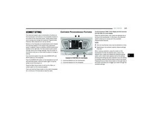 107
107 108
108 109
109 110
110 111
111 112
112 113
113 114
114 115
115 116
116 117
117 118
118 119
119 120
120 121
121 122
122 123
123 124
124 125
125 126
126 127
127 128
128 129
129 130
130 131
131 132
132 133
133 134
134 135
135 136
136 137
137 138
138 139
139 140
140 141
141 142
142 143
143 144
144 145
145 146
146 147
147 148
148 149
149 150
150 151
151 152
152 153
153 154
154 155
155 156
156 157
157 158
158 159
159 160
160 161
161 162
162 163
163 164
164 165
165 166
166 167
167 168
168 169
169 170
170 171
171 172
172 173
173 174
174 175
175 176
176 177
177 178
178 179
179 180
180 181
181 182
182 183
183 184
184 185
185 186
186 187
187 188
188 189
189 190
190 191
191 192
192 193
193 194
194 195
195 196
196 197
197 198
198 199
199 200
200 201
201 202
202 203
203 204
204 205
205 206
206 207
207 208
208 209
209 210
210 211
211 212
212 213
213 214
214 215
215 216
216 217
217 218
218 219
219 220
220 221
221 222
222 223
223 224
224 225
225 226
226 227
227 228
228 229
229 230
230 231
231 232
232 233
233 234
234 235
235 236
236 237
237 238
238 239
239 240
240 241
241 242
242 243
243 244
244 245
245 246
246 247
247 248
248 249
249 250
250 251
251 252
252 253
253 254
254 255
255