Page 160 of 498
1583-1. CONTROLS
■Gearshift
Gear shifting is only carried out at
the appropriate engine RPM and
vehicle speed.
■Short-term manual operation
In selector lever position D, operat-
ing a shift paddle causes the sys-
tem to switch to manual operation
temporarily.
The gearbox reverts to automatic
operation from manual operation
after a certain period of time of
moderate driving without accelera-
tion or gear shifts using the shift
paddles.
Changing to automatic operation is
possible as follows:
Pull and hold the right shift pad-
dle until D is shown in the instru-
ment cluster.
In addition to pulling the right
shift paddle, pull the left shift
paddle.
■Permanent manual operation
In selector lever position M, operat-
ing a shift paddle causes the sys-
tem to switch permanently to
manual operation (mode).
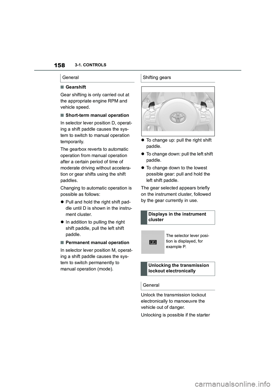
To change up: pull the right shift
paddle.
To change down: pull the left shift
paddle.
To change down to the lowest
possible gear: pull and hold the
left shift paddle.
The gear selected appears briefly
on the instrument cluster, followed
by the gear currently in use.
Unlock the transmission lockout
electronically to manoeuvre the
vehicle out of danger.
Unlocking is possible if the starter
GeneralShifting gears
Displays in the instrument
cluster
The selector lever posi-
tion is displayed, for
example P.
Unlocking the transmission
lockout electronically
General
Page 161 of 498
159
3
3-1. CONTROLS
CONTROLS
can turn the engine.
Before the transmission lockout is
released, apply the parking brake
to prevent the ve hicle from rolling
away.
1 Apply the brakes and keep them
applied.
2 Press the start/stop button. The
starter must be heard to start
turning. Press and hold the
start/stop button.
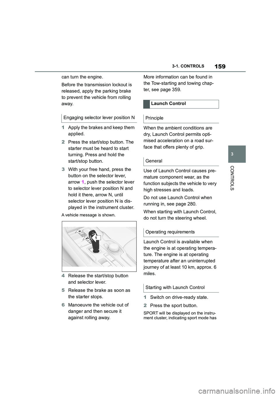
3 With your free hand, press the
button on the selector lever,
arrow 1, push the selector lever
to selector lever position N and
hold it there, arrow N, until
selector lever position N is dis-
played in the instrument cluster.
A vehicle message is shown.
4 Release the start/stop button
and selector lever.
5 Release the brake as soon as
the starter stops.
6 Manoeuvre the vehicle out of
danger and then secure it
against rolling away.
More information can be found in
the Tow-starting and towing chap-
ter, see page 359.
When the ambient conditions are
dry, Launch Control permits opti-
mised acceleration on a road sur-
face that offers plenty of grip.
Use of Launch Control causes pre-
mature component wear, as the
function subjects t he vehicle to very
high stresses and loads.
Do not use Launch Control when
running in, see page 280.
When starting with Launch Control,
do not turn the steering wheel.
Launch Control is available when
the engine is at operating tempera-
ture. The engine is at operating
temperature after an uninterrupted
journey of at least 10 km, approx. 6
miles.
1 Switch on drive-ready state.
2 Press the sport button.
SPORT will be displayed on the instru-
ment cluster, indicating sport mode has
Engaging selector lever position N
1
R
N
Launch Control
Principle
General
Operating requirements
Starting with Launch Control
Page 162 of 498
1603-1. CONTROLS
been selected.
3 Press the button.
TRACTION will be displayed on the instrument cluster and the VSC OFF
indicator lamp will illuminate.
4 Select the D selector lever posi-
tion.
5 Firmly depress the brake pedal
with your left foot.
6 Fully depress and hold the
accelerator pedal at the kick-
down position.
A flag symbol will be shown in the instrument cluster.
7 The engine speed will be
adjusted for launching. Release
the brake pedal within 3 sec-
onds.
Once Launch Control has been
used, the transmission requires
approximately 5 minutes to cool
down before Launch Control can be
used again. Launch Control adapts
to the ambient conditions when
used again.
To support driving stability, re-acti-
vate Vehicle Stab ility Control, VSC
as soon as possible.
An experienced driver may be able
to achieve better acceleration val-
ues in VSC OFF mode.
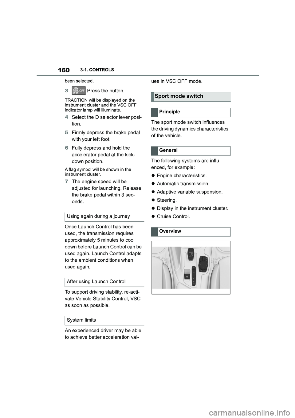
The sport mode switch influences
the driving dynamics characteristics
of the vehicle.
The following systems are influ-
enced, for example:
Engine characteristics.
Automatic transmission.
Adaptive variable suspension.
Steering.
Display in the instrument cluster.
Cruise Control. Using again during a journey
After using Launch Control
System limits
Sport mode switch
Principle
General
Overview
Page 163 of 498
161
3
3-1. CONTROLS
CONTROLS
The NORMAL drive mode is auto-
matically selected when
drive-ready state is switched on.
■Principle
Balanced configuration between
dynamic and efficient driving.
■Principle
Dynamic configuration for greater
agility with an optimised suspen-
sion.
■Switching on
■Principle
Individual settings can be made in
SPORT INDIVIDUAL drive mode.
■Configuring
Via Toyota Supra Command:
1 "My Vehicle"
2 "Vehicle settings"
3 "Configure SPORT INDIVID-
UAL"
4 "Customise Settings"
5 Select the desired setting.
Reset customize settings to default
setting:
"Reset to SPORT STANDARD".
Displays in the instrument
cluster
The selected drive mode
is shown in the instru-
ment cluster.
Drive modes
Button in the vehicle
ButtonDrive
mode
Configu-
ration
SPORTSPORTCustom-
ise
Drive modes in detail
NORMAL
SPORT
Press the button.
SPORT INDIVIDUAL
Page 164 of 498
1623-1. CONTROLS
This chapter describes all standard,
country-specific and special equip-
ment available for the model series.
It may therefore describe equip-
ment and functions which are not
installed in your vehicle, for exam-
ple on account of the special equip-
ment selected or the country
specification. This also applies to
safety-relevant functions and sys-
tems. Please comply with the rele-
vant laws and regulations when
using the corresponding functions
and systems.
The instrument cluster is a variable
display. When the sport mode
switch is used to change the driving
mode, the instrument cluster dis-
plays change to match the driving
mode.
Changes to the displays in the
instrument cluster can be deacti-
vated via Toyota Supra Command.
The displays in the instrument clus-
ter can sometimes differ from the
illustrations in th is Owner's Manual.
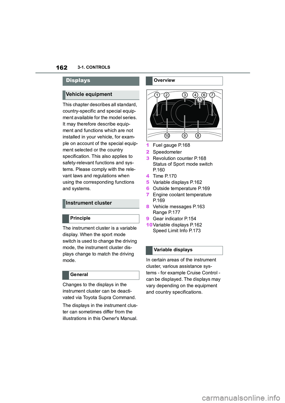
1 Fuel gauge P.168
2 Speedometer
3 Revolution counter P.168
Status of Sport mode switch
P. 1 6 0
4 Time P.170
5 Variable displays P.162
6 Outside temperature P.169
7 Engine coolant temperature
P. 1 6 9
8 Vehicle messages P.163
Range P.177
9 Gear indicator P.154
10 Variable displays P.162
Speed Limit Info P.173
In certain areas of the instrument
cluster, various assistance sys-
tems - for example Cruise Control -
can be displayed. The displays may
vary depending on the equipment
and country specifications.
Displays
Vehicle equipment
Instrument cluster
Principle
General
Overview
Variable displays
Page 165 of 498
163
3
3-1. CONTROLS
CONTROLS
The display can be changed for
sport mode.
The driving mode will change to
sport mode.
The vehicle messages monitors
vehicle functions and alerts you to
any faults in the monitored sys-
tems.
A vehicle message is displayed as
a combination of indicator or warn-
ing lamps and text messages in the
instrument cluster and, if applica-
ble, in the Head-Up Display.
If applicable, the text message
shown in the Control Display is
accompanied by an additional
acoustic signal.
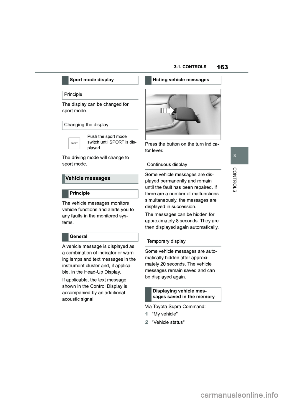
Press the button on the turn indica-
tor lever.
Some vehicle messages are dis-
played permanently and remain
until the fault has been repaired. If
there are a number of malfunctions
simultaneously, the messages are
displayed in succession.
The messages can be hidden for
approximately 8 seconds. They are
then displayed again automatically.
Some vehicle messages are auto-
matically hidden after approxi-
mately 20 seconds. The vehicle
messages remain saved and can
be displayed again.
Via Toyota Supra Command:
1 "My vehicle"
2 "Vehicle status"
Sport mode display
Principle
Changing the display
Push the sport mode
switch until SPORT is dis-
played.
Vehicle messages
Principle
General
Hiding vehicle messages
Continuous display
Temporary display
Displaying vehicle mes-
sages saved in the memory
Page 166 of 498
1643-1. CONTROLS
3"Vehicle messages"
4 Select a text message.
Text messages and symbols in the
instrument cluster explain the
meaning of a vehicle message and
the indicator and warning lamps.
You can call up additional informa-
tion via vehicle messages, for
example the cause of the fault and
any action required.
If the message is urgent, the sup-
plementary text is shown in the
Control Display automatically.
It is possible to select additional
assistance depending on the vehi-
cle message.
Via Toyota Supra Command:
1 "My vehicle"
2 "Vehicle status"
3 "Vehicle messages"
4 Select the required text mes-
sage.
5 Select the desired setting
Certain messages displayed when
driving are displayed again when
drive-ready state is switched off.
Indicator and warning lamps in the
instrument cluster show the status
of some functions in the vehicle and
indicate any malfunctions in moni-
tored systems.
Indicator and warning lamps can
illuminate in a variety of combina-
tions and colours.
When drive-ready state is switched
on, the functionality of some lights
is checked and they illuminate
briefly.
Display
Vehicle messages
At least one vehicle mes-
sage is displayed or
saved.
Text messages
Supplementary text messages
Messages displayed at the end of
a journey
Indicator and warning lamps
Principle
General
Page 170 of 498
1683-1. CONTROLS
The current fill level of the fuel tank
is displayed.
The angle of the vehicle may cause
the display to fluctuate.
For notes on refuelling, see page
290.
It is vital to avoid engine speeds in
the red warning zone. In this zone,
the fuel supply is interrupted to pro-
tect the engine.
Depending on the equipment, the
shift lights on the revolution counter
indicate the maximum shift point at
which the best possible accelera-
tion can be achieved.
When the selected driving mode is
sport mode, a shift light will be dis-
played.
1 Select SPORT using the sport
mode switch.
2 Activate manual mode of the
transmission.
Automatic high-beam
Automatic high-beams
switched on.
The high-beam head-
lights are switched on and
off automatically depend-
ing on the traffic situation.
Automatic high-beam, see
page 188.
Blue lights
High-beam headlights
The high-beam head-
lights are switched on.
High-beam headlights,
see page 150.
Fuel gauge
Principle
General
Display
An arrow next to the petrol
pump symbol shows
which side of the vehicle
the fuel filler flap is on.
Revolution counter
Shift lights
Principle
Operating requirements
Switching on Shift Lights