2022 TOYOTA SUPRA display
[x] Cancel search: displayPage 267 of 498
265
3
3-1. CONTROLS
CONTROLS
In order to protect the battery the
air flow rate of the automatic air
conditioning is reduced, if neces-
sary.
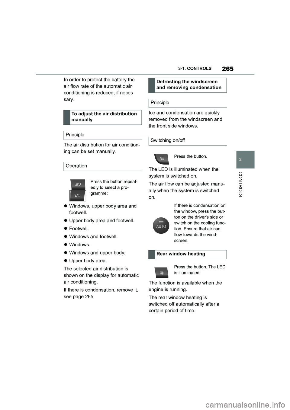
The air distribution for air condition-
ing can be set manually.
Windows, upper body area and
footwell.
Upper body area and footwell.
Footwell.
Windows and footwell.
Windows.
Windows and upper body.
Upper body area.
The selected air distribution is
shown on the display for automatic
air conditioning.
If there is condensation, remove it,
see page 265.
Ice and condensation are quickly
removed from the windscreen and
the front side windows.
The LED is illuminated when the
system is switched on.
The air flow can be adjusted manu-
ally when the system is switched
on.
The function is available when the
engine is running.
The rear window heating is
switched off automatically after a
certain period of time.
To adjust the air distribution
manually
Principle
Operation
Press the button repeat-
edly to select a pro-
gramme:
Defrosting the windscreen
and removing condensation
Principle
Switching on/off
Press the button.
If there is condensation on
the window, press the but-
ton on the driver's side or
switch on the cooling func-
tion. Ensure that air can
flow towards the wind-
screen.
Rear window heating
Press the button. The LED
is illuminated.
Page 270 of 498
2683-1. CONTROLS
3"Climate comfort"
4 "Auxiliary ventilation"
5 "Activate now"
symbol on the automatic air con-
ditioning signals that the system is
switched on.
REST is shown on the air condition-
ing system. The residual heat of the
engine is being used.
To ensure a pleasant interior tem-
perature in the vehicle at the start
of the journey, it is possible to set
different departure times.
One-off departure time: the time
can be set.
System is switched on once.
Departure time with day of the
week: time and day of the week
can be set.
The system is switched on in good time
before the set departure time on the
required days of the week.
Departure time pre-selection is
done in two stages:
Set departure times.
Activate departure time.
At least 10 minutes should pass
between adjusting/ activating the
departure time and the scheduled
departure time, so the climate con-
trol has enough time to work.
■Via Toyota Supra Command
1 "My vehicle"
2 "Vehicle settings"
3 "Climate comfort"
4 "Auxiliary ventilation"
5 Select the required departure
time.
6 Set the departure time.
7 Select the day of the week if
necessary.
■Operating requirements
If a departure time is to control
when the independent ventilation is
switched on, the relevant depar-
ture time must be activated first.
■Via Toyota Supra Command
1 "My vehicle"
2 "Vehicle settings"
3 "Climate comfort"
4 "Auxiliary ventilation"
5 "For departure time"
6 Activate the required departure
time.
Symbol on the automatic air con-
ditioning system signals that a
Display
Departure time
Principle
Setting the departure time
Activating the departure time
Display
Page 274 of 498
2723-1. CONTROLS
The mobile telephone must sup-
port and be compatible with the
required Qi standard.
Standby state is switched on.
Note the maximum dimensions
of the mobile telephone.
Only use protective sleeves and
covers up to a maximum thick-
ness of 2 mm, 0.07 in, otherwise,
charging function may be
impaired.
The mobile telephone to be
charged is located in the middle
of the dock.
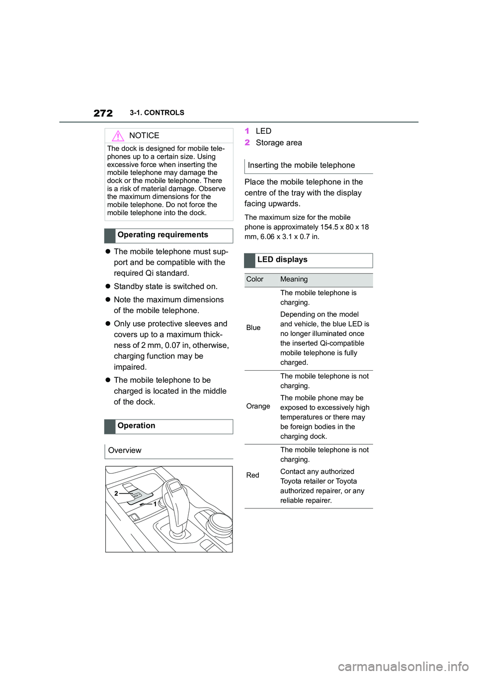
1 LED
2 Storage area
Place the mobile telephone in the
centre of the tray with the display
facing upwards.
The maximum size for the mobile
phone is approximately 154.5 x 80 x 18
mm, 6.06 x 3.1 x 0.7 in.
NOTICE
The dock is designed for mobile tele-
phones up to a certain size. Using
excessive force when inserting the mobile telephone may damage the
dock or the mobile telephone. There
is a risk of material damage. Observe the maximum dimensions for the
mobile telephone. Do not force the
mobile telephone into the dock.
Operating requirements
Operation
Overview
Inserting the mobile telephone
LED displays
ColorMeaning
Blue
The mobile telephone is
charging.
Depending on the model
and vehicle, the blue LED is
no longer illuminated once
the inserted Qi-compatible
mobile telephone is fully
charged.
Orange
The mobile telephone is not
charging.
The mobile phone may be
exposed to excessively high
temperatures or there may
be foreign bodies in the
charging dock.
Red
The mobile telephone is not
charging.
Contact any authorized
Toyota retailer or Toyota
authorized repairer, or any
reliable repairer.
Page 292 of 498
2905-1. MOBILITY
5-1.MOBILITY
This chapter describes all standard,
country-specific and special equip-
ment available for the model series.
It may therefore describe equip-
ment and functions which are not
installed in your vehicle, for exam-
ple on account of the special equip-
ment selected or the country
specification. This also applies to
safety-relevant functions and sys-
tems. Please comply with the rele-
vant laws and regulations when
using the corresponding functions
and systems.
Before refuelling, observe the notes
on fuel quality, see page 322.
When refuelling, insert the filler
nozzle fully into th e filler neck. Lift-
ing the filler nozzle during refuelling
results in the following:
The fuel supply being cut off pre-
maturely.
Fuel vapour and fumes being
recovered less effectively.
The fuel tank is full when the filler
nozzle cuts out for the first time.
For Korea: Make sure that the fuel
tank cap is closed properly after
refuelling, otherw ise the emissions
warning lamp may illuminate.
Please comply with the safety regu-
lations displayed at filling stations.
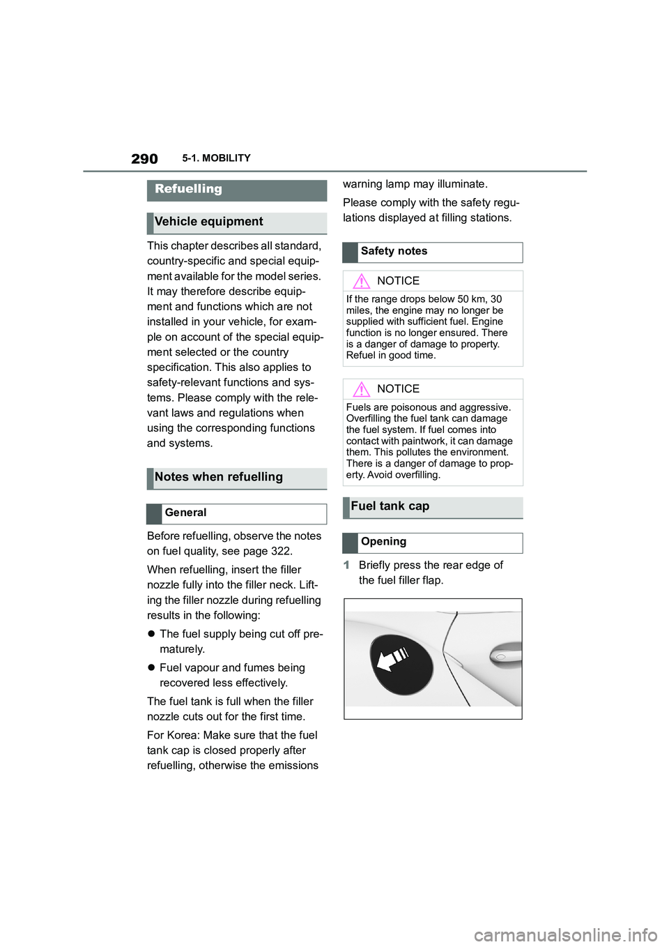
1 Briefly press the rear edge of
the fuel filler flap.
Refuelling
Vehicle equipment
Notes when refuelling
General
Safety notes
NOTICE
If the range drops below 50 km, 30
miles, the engine may no longer be
supplied with sufficient fuel. Engine function is no longer ensured. There
is a danger of damage to property.
Refuel in good time.
NOTICE
Fuels are poisonous and aggressive.
Overfilling the fuel tank can damage the fuel system. If fuel comes into
contact with paintwork, it can damage
them. This pollutes the environment. There is a danger of damage to prop-
erty. Avoid overfilling.
Fuel tank cap
Opening
Page 295 of 498
293
5
5-1. MOBILITY
MOBILITY
ized Toyota reta iler or Toyota
authorized repairer, or any reliable
repairer.
The tyre inflation pressure appropri-
ate for the respective load condi-
tions should be used. For example,
if the vehicle is partially loaded, use
the tyre inflation pressure specified
for a partially loaded vehicle.
The current tire pr essure of each
installed wheel can be displayed on
the control display.
To ensure that they are displayed
correctly, the tyre sizes must be
stored in the system and must have
been set, see page 304, for the
mounted tyres.
The current tyre inflation pressure
value is shown on each tyre.
Tyres heat up while driving. The
tyre inflation pressure increases
with the temperature of the tyre.
Tyres have a natural, uniform loss
of tyre inflation pressure.
Inflating devices can display a pres-
sure that may be up to 0.1 bar too
low.
The tyre inflation pressure inscrip-
tions on the tyre inflation pressure
sign on the door pillar only relate to
cold tyres or tyres at the same tem-
perature as the ambient tempera-
ture.
Only check the tyre inflation pres-
sures when the tyres are cold, i.e.:
• If the vehicle has been driven a
distance of no more than 2 km,
1.25 miles.
• If the vehicle has not moved
again for at least 2 hours after a
journey.
Regularly check the tyre inflation
pressure of the emergency wheel in
the boot and correct the pressure if
necessary.
1 Determine the specified tyre
inflation pressures for the tyres
installed on the vehicle.
For Australia/New Zealand
WA R N I N G
The inflation pressures on the tyre
label are applicable only for tyres
explicitly mentioned on the label. Inflation pressures for tyres that may
be covered by the label – by size,
speed category and load rating/load index – but not explicitly mentioned
on the label may be different. Please
obtain adequate inflation pressures in accordance with the tyre manufac-
turer's specifications from your tyre
dealer.
On the Control Display
Checking the tyre inflation
pressure
General
Checking using tyre inflation pres-
sure inscriptions on the door pillar
Page 296 of 498
2945-1. MOBILITY
2Check the tyre inflation pressure
in all four tyres, using a pressure
gauge, for example.
3 Correct the tyre inflation pres-
sure if the current tyre inflation
pressure value deviates from
the specified value.
4 Check whether all valve caps
are screwed onto the tyre
valves.
Via Toyota Supra Command:
1 "My vehicle"
2 "Vehicle status"
3 "Tyre Pressure Monitor"
4 Check if the current tyre inflation
pressures match the specified
tyre pressure value.
5 Correct the tyre inflation pres-
sure if the current tyre inflation
pressure value deviates from
the specified value.
For Tyre Pressure Monitor (TPM):
The corrected tyre inflation pres-
sures are applied automatically.
Make sure that the correct tyre set-
tings have been performed.
For tyres that cannot be found in
the tyre inflation pressure informa-
tion on the Control Display, reset
the Tyre Pressure Monitor (TPM).
The tyre tread depth should not be
less than 3 mm, 0.12 in, otherwise
there is a high risk of aquaplaning.
The tyre tread depth should not be
less than 4 mm, 0.16 in, otherwise
the vehicle's suitability for winter
use is restricted.
Checking using the tyre inflation
pressure information on the Con-
trol Display
After adjusting the tyre inflation
pressure
Speed code
DesignationMaximum speed
Qup to 160 km/h, 100 mph
Rup to 170 km/h, 106 mph
Sup to 180 km/h, 112 mph
Tup to 190 km/h, 118 mph
Hup to 210 km/h, 131 mph
Fup to 240 km/h, 150 mph
Wup to 270 km/h, 167 mph
Yup to 300 km/h, 186 mph
Tyre tread
Summer tyres
Winter tyres
Page 297 of 498
295
5
5-1. MOBILITY
MOBILITY
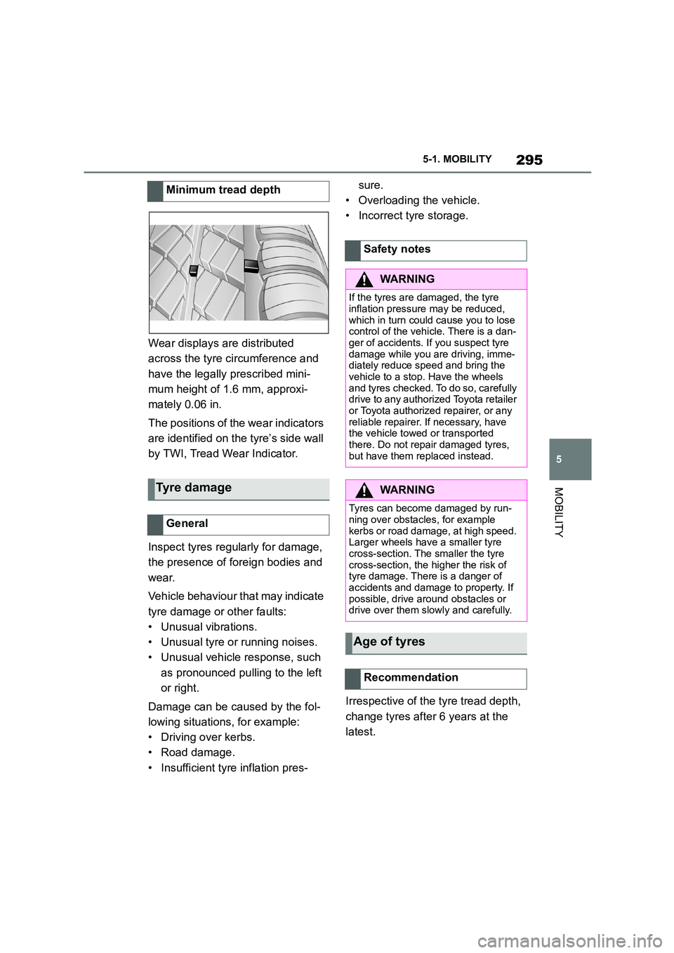
Wear displays are distributed
across the tyre circumference and
have the legally prescribed mini-
mum height of 1.6 mm, approxi-
mately 0.06 in.
The positions of the wear indicators
are identified on the tyre’s side wall
by TWI, Tread Wear Indicator.
Inspect tyres regularly for damage,
the presence of foreign bodies and
wear.
Vehicle behaviour that may indicate
tyre damage or other faults:
• Unusual vibrations.
• Unusual tyre or running noises.
• Unusual vehicle response, such
as pronounced pu lling to the left
or right.
Damage can be caused by the fol-
lowing situations, for example:
• Driving over kerbs.
• Road damage.
• Insufficient tyre inflation pres-
sure.
• Overloading the vehicle.
• Incorrect tyre storage.
Irrespective of the tyre tread depth,
change tyres after 6 years at the
latest.
Minimum tread depth
Tyre damage
General
Safety notes
WA R N I N G
If the tyres are damaged, the tyre
inflation pressure may be reduced,
which in turn could cause you to lose control of the vehicle. There is a dan-
ger of accidents. If you suspect tyre
damage while you are driving, imme- diately reduce speed and bring the
vehicle to a stop. Have the wheels
and tyres checked. To do so, carefully drive to any authorized Toyota retailer
or Toyota authorized repairer, or any
reliable repairer. If necessary, have the vehicle towed or transported
there. Do not repair damaged tyres,
but have them replaced instead.
WA R N I N G
Tyres can become damaged by run-
ning over obstacles, for example
kerbs or road damage, at high speed. Larger wheels have a smaller tyre
cross-section. The smaller the tyre
cross-section, the higher the risk of tyre damage. There is a danger of
accidents and damage to property. If
possible, drive around obstacles or drive over them slowly and carefully.
Age of tyres
Recommendation
Page 306 of 498

3045-1. MOBILITY
3Insert the plug into the socket in
the vehicle interior.
4 Correct tyre inflation pressure to
at least 2.0 bar.
• To increase tyre inflation pres-
sure: switch on the compressor
with standby state switched on or
the engine running.
• To reduce tyre inflation pressure:
press the button on the compres-
sor.
5 Unscrew the connecting hose of
the compressor from the tyre
valve.
6 Unplug the connector from the
socket in the vehicle interior.
7 Store Mobility System in the
vehicle.
Do not exceed maximum permitted
speed of 80 km/h, approximately 50
mph.
Reset the Tyre Pressure Monitor
(TPM), see page 304.
Have the punctured tyre and the
sealant containe r of the Mobility
System replaced as soon as possi-
ble.
Tire chains cannot be mounted.
Snow tires should be used instead.
The system monitors the tyre infla-
tion pressure in the four fitted tyres.
The system warns if the tyre infla-
tion pressure in one or more tyres
has fallen.
Sensors in the tyre valves measure
the tyre inflation pressure and tyre
temperature.
The system detects the fitted tyres
automatically. The system shows
the preset specified pressures on
the Control Display and compares
them to the current tyre inflation
pressures.
If tyres are fitted which are not
listed on the tyre inflation pressure
labels in the vehicle, see page 292,
Resuming with journey
Snow chains
Selecting tire chains
NOTICE
■Driving with tire chains
Do not fit tire chains. Tire chains may
damage the vehicle body and sus- pension, and adversely affect driving
performance.
Tyre Pressure Monitor (TPM)
Principle
General