2022 TOYOTA SUPRA jump start
[x] Cancel search: jump startPage 272 of 498
2703-1. CONTROLS
cal devices when standby state or
drive-ready state is switched on.
The total load of all sockets must
not exceed 140 watts at 12 volts.
To avoid damage to the socket, do
not insert an incompatible plug.
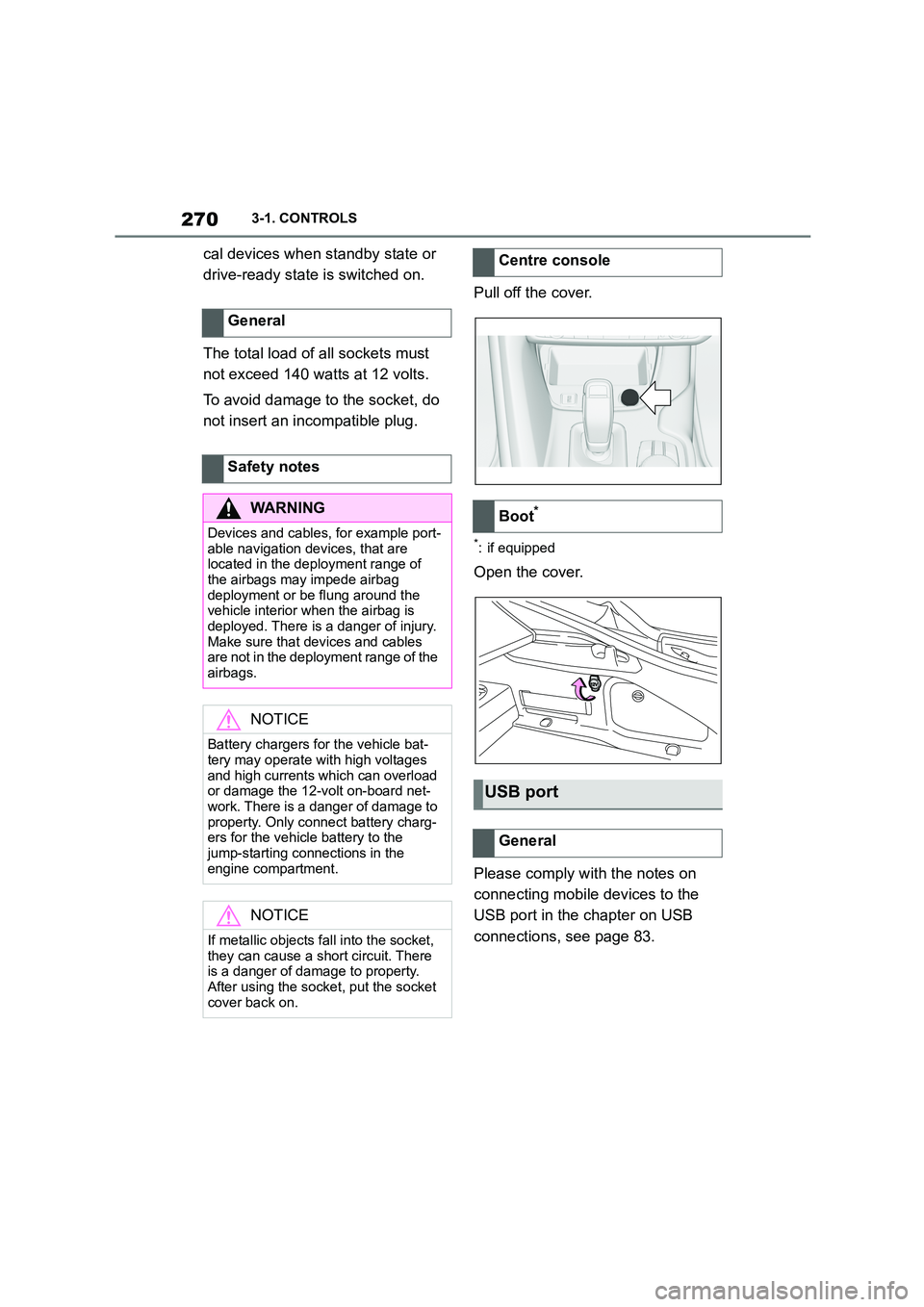
Pull off the cover.
*: if equipped
Open the cover.
Please comply with the notes on
connecting mobile devices to the
USB port in the chapter on USB
connections, see page 83.
General
Safety notes
WA R N I N G
Devices and cables, for example port-
able navigation devices, that are located in the deployment range of
the airbags may impede airbag
deployment or be flung around the vehicle interior when the airbag is
deployed. There is a danger of injury.
Make sure that devices and cables are not in the deployment range of the
airbags.
NOTICE
Battery chargers for the vehicle bat- tery may operate with high voltages
and high currents which can overload
or damage the 12-volt on-board net- work. There is a danger of damage to
property. Only connect battery charg-
ers for the vehicle battery to the jump-starting connections in the
engine compartment.
NOTICE
If metallic objects fall into the socket,
they can cause a short circuit. There
is a danger of damage to property.
After using the socket, put the socket cover back on.
Centre console
Boot*
USB port
General
Page 344 of 498
3425-1. MOBILITY
The installed battery is designed
specifically for this vehicle. If an
inappropriate battery is used, oper-
ation of the Auto Start/Stop function
may be restricted in order to protect
the battery. Also, the battery may
deteriorate faster than normal and
the engine may not be able to be
restarted. Contact any authorized
Toyota retailer or Toyota authorized
repairer, or any reliable repairer.
The battery is operational. No spe-
cial precautions are required for
start-up.
Ensure the battery is sufficiently
charged to guarantee the entire life-
time of the battery.
Charge the battery under the fol-
lowing circumstances:
If the inspection glass on the top
of the battery is black.
If there is insufficient starting
capability.
The following condit ions can have a
negative effect on battery output:
Frequently driving short dis-
tances.
If the vehicle is not used for peri-
ods of longer than one month.
Only charge the battery via the
jump-starting connections, see
page 358, in the engine compart-
ment and with the engine switched
off.
Battery chargers developed espe-
cially for the vehicle and suitable for
the on-board network can be
obtained from any authorized
Toyota retailer or Toyota authorized
Follow the user manual.
Explosive gas mixture.
Do not seal any open-
ings on the battery.
When replacing the battery
Initial operation
Charging the battery
General
A red indicator lamp is dis-
played if the battery is flat.
SymbolMeaning
Safety note
NOTICE
Battery chargers for the vehicle bat-
tery may operate with high voltages
and high currents which can overload or damage the 12-volt onboard net-
work. There is a danger of damage to
property. Only connect battery charg- ers for the vehicle battery to the
jump-starting connections in the
engine compartment.
Jump-starting connections
Battery charger
Page 359 of 498
357
5
5-1. MOBILITY
MOBILITY
Open the buckles on the retaining
strap.
To use the fire extinguisher, follow
the manufacturer's instructions on
the fire extinguisher and the infor-
mation supplied with it.
1 Insert the fire extinguisher into
the holder.
2 Hook in and close the buckles.
Have the fire extinguisher checked
every 2 years by any authorized
Toyota retailer or Toyota authorized
repairer, or any reliable repairer.
Take note of the next maintenance
date for the fire extinguisher.
Replace the fire extinguisher after
use or have it refilled.
If the vehicle battery is discharged,
the engine can be started from
another vehicle's battery using two
jump leads. Only use jump leads
with fully insulated terminal clamps.
1 Check whether the battery in the
other vehicle shows 12 volts.
Information about the voltage is
provided on the battery.
2 Switch off the engine of the
other vehicle.
WA R N I N G
Objects in the driver's footwell can
restrict the pedal travel or block a
pedal that has been pressed. There is a risk of accident. Ensure that items in
the vehicle are stowed securely and
cannot get into the driver's footwell.
Taking out the fire extin-
guisher
Using the fire extinguisher
Stowing the fire extinguisher
Maintenance and refilling
Starting assistance
General
Safety notes
WA R N I N G
Touching live components can result
in an electric shock. There is a danger
of injury or even death. Do not touch any components that could be live.
WA R N I N G
Connecting the jump leads in the wrong sequence can cause sparks.
There is a danger of injury. Please
comply with the correct sequence
when connecting up.
NOTICE
Contact between the bodywork of the
two vehicles can result in a short cir- cuit during starting assistance. There
is a danger of damage to property.
Make sure there is no contact between the bodywork.
Preparations
Page 360 of 498
3585-1. MOBILITY
3Switch off any power consumers
in both vehicles.
The jump-starting connection in the
engine compartment serves as the
battery positive terminal.
A special connection on the body
serves as the negative battery ter-
minal in the engine compartment.
For further information:
Overview of the engine compart-
ment, see page 320.
Open the lid of the positive battery
terminal.
Before starting, switch off all unnec-
essary power consumers, for
example the radio, on both vehi-
cles.
1 Open the cover of the
jump-starting connection.
2 Connect a terminal clamp on the
positive/+ jump lead to the posi-
tive terminal of the battery or the
corresponding jump-starting
connection on the donor vehicle.
3 Connect the second terminal
clamp to the battery's positive
terminal or to the corresponding
jump-starting connection on the
vehicle to be started.
4 Connect a terminal clamp on the
negative/– jump lead to the neg-
ative terminal of the battery or
the corresponding engine or
body earth connection on the
donor vehicle.
5 Connect the second terminal
clamp to the negative terminal of
the battery or to a corresponding
engine or body earth connection
on the vehicle to be started.
Do not use spray products sold as
starting aids.
1 Start the engine of the donor
vehicle and allow it to run for a
few minutes at a slightly
increased idle speed.
2 Start the engine of the vehicle to
be started as normal.
If an initial attempt to start the engine
fails, wait several minutes until the dis-
charged battery has been recharged somewhat.
3 Allow both engines to run for a
few minutes.
4 Disconnect the jump leads in
reverse order to connection.
Check the battery and have it
recharged if necessary.
Jump-starting connections
Connecting the cables
Starting the engine
Page 491 of 498
489Alphabetical Index
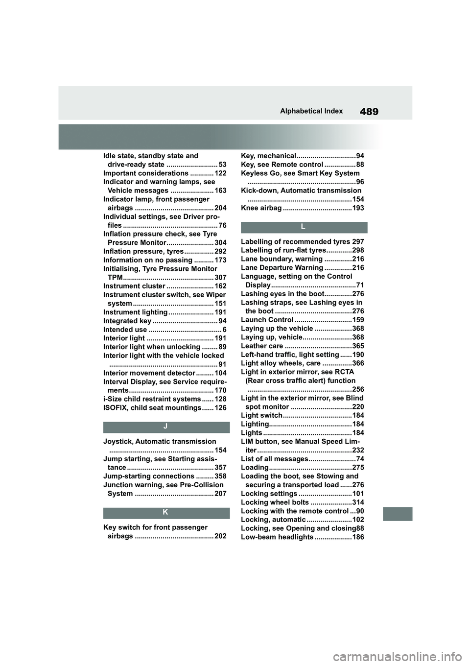
Idle state, standby state and
drive-ready state .......................... 53
Important considerations ............ 122
Indicator and warning lamps, see
Vehicle messages ...................... 163
Indicator lamp, front passenger
airbags ........................................ 204
Individual settings, see Driver pro-
files ................................................ 76
Inflation pressure check, see Tyre
Pressure Monitor........................ 304
Inflation pressure, tyres ............... 292
Information on no passing .......... 173
Initialising, Tyre Pressure Monitor
TPM.............................................. 307
Instrument cluster ........................ 162
Instrument cluster switch, see Wiper
system ......................................... 151
Instrument lighting ....................... 191
Integrated key ................................. 94
Intended use ..................................... 6
Interior light .................................. 191
Interior light when unlocking ........ 89
Interior light with the vehicle locked
....................................................... 91
Interior movement detector ......... 104
Interval Display, see Service require-
ments........................................... 170
i-Size child restraint systems ...... 128
ISOFIX, child seat mountings...... 126
J
Joystick, Automatic transmission
..................................................... 154
Jump starting, see Starting assis-
tance ............................................ 357
Jump-starting connections ......... 358
Junction warning, see Pre-Collision
System ........................................ 207
K
Key switch for front passenger
airbags ........................................ 202
Key, mechanical .............................. 94
Key, see Remote control ................ 88
Keyless Go, see Smart Key System
....................................................... 96
Kick-down, Automatic transmission
..................................................... 154
Knee airbag ...................................193
L
Labelling of recommended tyres 297
Labelling of run-flat tyres.............298
Lane boundary, warning .............. 216
Lane Departure Warning .............. 216
Language, setting on the Control
Display........................................... 71
Lashing eyes in the boot.............. 276
Lashing straps, see Lashing eyes in
the boot ....................................... 276
Launch Control .............................159
Laying up the vehicle ................... 368
Laying up, vehicle......................... 368
Leather care .................................. 365
Left-hand traffic, lig ht setting ...... 190
Light alloy wheels, care ...............366
Light in exterior mirror, see RCTA
(Rear cross traffic alert) function
..................................................... 256
Light in the exterior mirror, see Blind
spot monitor ............................... 220
Light switch ...................................184
Lighting.......................................... 184
Lights ............................................. 184
LIM button, see Manual Speed Lim-
iter ................................................ 232
List of all messages........................ 74
Loading .......................................... 275
Loading the boot, see Stowing and
securing a transported load ...... 276
Locking settings ...........................101
Locking wheel bolts .....................314
Locking with the remote control ... 90
Locking, automatic .......................102
Locking, see Opening and closing88
Low-beam headlights ................... 186