Page 333 of 502

Fault in exhaust system
The yellow catalytic converter lamp lights up or flashes.
Faults in the exhaust system caused by misfiring, which can damage the catalytic converter.
to the nearest qualified workshop immediately.
There may be engine faults and fuel consumption may be higher if the indicator lamps are lit up or
flashing.
If and when
Vehicle toolkit
Introduction
This chapter contains information on the followingsubjects:
⇒ Stowage
⇒ Vehicle toolkit contents
Observe any country-specific legislation when securing your vehicle in the event of a breakdown.
Vehicle toolkit in the vehicle
In vehicles that are factory-fitted with a spare wheel, emergency spare wheel or winter wheels,
additional vehicle tools may be located in the luggage compartment.
WARNING
In the event of a sudden driving or braking manoeuvre or accident, a loose vehicle toolkit,
breakdown set and spare wheel or temporary spare wheel could be flung though the vehicle and
cause severe injuries.
always secured in the luggage compartment.
WARNING
Unsuitable or damaged tools in the vehicle toolkit can lead to accidents and injuries.
Stowage
Page 346 of 502

⇒ Fuses in the engine compartment
⇒ Fuse table for fuses in the dash panel
⇒ Fuse tables for fuses in the engine compartment
⇒ Changing a blown fuse
At the time of publication we are unable to provide an complete overview of the locations of the
fuses for the electrical consumers. This is because the vehicle is under constant development,
because fuses are assigned differently according to the vehicle equipment level and because several
electrical consumers may use a single fuse. You can obtain more information about the fuse
assignment from a Volkswagen dealership.
Several electrical consumers can share a single fuse. Conversely, a single consumer could have more
than one fuse.
Therefore fuses should only be replaced when the cause of the fault has been rectified. If a new fuse
blows shortly after fitting, have the electrical system checked by a qualified workshop.
WARNING
High voltages in the electrical system can cause electric shocks, serious burns and death.
WARNING
Using unsuitable or repaired fuses and bridging an electrical circuit without fuses can cause a fire
and serious injuries.
fuse with the same amp rating (same colour and markings) and size.
NOTICE
electrical consumers off and remove the vehicle key from the ignition before changing a fuse.
pened. Dirt and moisture in the fuse
boxes can damage the electrical system.
Page 349 of 502

boxes can damage the electrical system.
Fuse table for fuses in the dash panel
Fig. 173 In the dash panel: fuse assignment.
First read and observe the introductoryinformation and safety warnings⇒Introduction
The table shows the fuse locations of the electrical consumers relevant for the driver. The first
column in the table contains the location. The other columns contain the fuse type, the amp rating
and the consumer protected by the fuse.
Depending on the market and specification of your vehicle, the fuse numbers and positions may
differ to those given in the table. If necessary, ask your Volkswagen dealership for the exact fuse
assignment.
Fuse location ⇒ Fig. 173
F410 amps, MINI®, anti-theft alarm.F710 amps, MINI®, air conditioning system control panel or
heating and fresh air system, rear window heating relay.F810 amps, MINI®, light switch (dipped
beam), rain/light sensor, electronic parking brake.F107.5 amps, MINI®, display, Infotainment control
panel.F1140 amps, ATO®, left exterior lighting.F1220 amps, ATO®, Infotainment
components.F1440 amps, ATO®, blower regulator.F167.5 amps, MINI®, telephone.F2215 amps,
ATO®, trailer charging cable.F2330 amps, JCASE®, electric glass roof.F2440 amps, ATO®, right
exterior lighting.F2630 amps, ATO®, seat heating.F2730 amps, ATO®, interior lighting.F2825 amps,
ATO®, left trailer control unit.F3825 amps, ATO®, right trailer control unit.F401)20 amps, ATO®,
cigarette lighter, sockets.F4240 amps, ATO®, central locking.F4415 amps, ATO®, trailer control
unit.F4715 amps, ATO®, rear window wiper.F5125 amps, ATO®, rear seat heating.F5330 amps, ATO®,
rear window heating.
Page 350 of 502

1) Note installation position. Factory-fitted fuse location as shown in illustration ⇒ Fig. 173 .
Fuse tables for fuses in the engine compartment
First read and observe the introductoryinformation and safety warnings⇒Introduction
The table shows the fuse locations of the electrical consumers relevant for the driver. The first
column in the table contains the location. The other columns contain the fuse type, the amp rating
and the consumer protected by the fuse.
Depending on the market and specification of your vehicle, the fuse numbers and positions may
differ to those given in the table. If necessary, ask your Volkswagen dealership for the exact fuse
assignment.
F65 amps, ATO®, brake light sensor.F1440 amps, JCASE®, windscreen heating.F1515 amps, ATO®,
horn.F1930 amps, ATO®, front wipers.F3720 amps, ATO®, auxiliary heater.
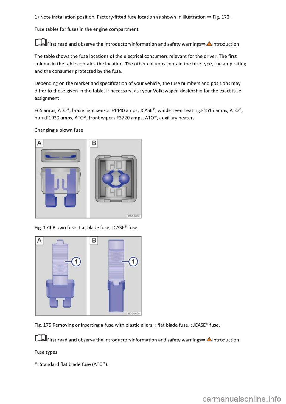
Changing a blown fuse
Fig. 174 Blown fuse: flat blade fuse, JCASE® fuse.
Fig. 175 Removing or inserting a fuse with plastic pliers: : flat blade fuse, : JCASE® fuse.
First read and observe the introductoryinformation and safety warnings⇒Introduction
Fuse types
Page 352 of 502

Introduction
This chapter contains information on the followingsubjects:
⇒ Jump lead connection point (earth connection)
⇒ Jump starting the vehicle
If the engine fails to start because the 12-volt vehicle battery is flat, the discharged battery can be
connected to the 12-volt battery of another vehicle to start the engine.
Suitable jump leads are needed for jump starting.
2 for vehicles with petrol engines.
WARNING
Using the jump leads incorrectly or performing the jump start procedure incorrectly can cause the
12-volt vehicle battery to explode, which can lead to severe injuries. Please note the following in
order to reduce the risk of the 12-volt vehicle battery exploding:
-volt vehicle battery and the electrical system can cause serious chemical burns,
fire or electric shocks. Always read the warnings and safety information before carrying out any kind
of work on the 12-volt vehicle battery ⇒ 12-volt vehicle battery .
volts) and approximately
the same capacity (see label on battery) as the flat 12-volt vehicle battery.
-volt vehicle battery. Discharged 12-volt vehicle batteries can
already freeze at temperatures of around 0°C (+32°F).
-volt vehicle battery should be replaced if it is or has ever been frozen.
-volt vehicle battery is jump started.
Always keep fire, sparks, naked flames and lit cigarettes away from the 12-volt vehicle battery.
Never use a mobile telephone when the jump leads are being connected or disconnected.
compartment.
rectly.
NOTICE
Please note the following in order to avoid considerable damage to the vehicle electrical system:
Page 354 of 502

Suitable earth connection: preferably the jump lead connection point (earth connection), a
solid metal part which is securely bolted onto the cylinder block, or the cylinder block itself.
The discharged 12-volt vehicle battery must be properly connected to the vehicle's electrical system.
The vehicles must not touch. Otherwise electricity could flow as soon as the positive terminals are
connected.
Ensure that the battery clamps have good metal-to-metal contact with the battery terminals.
If the engine does not start immediately, switch off the starter after about 10 seconds and try again
after about a minute.
If the engine still does not start, seek expert assistance.
Attaching the jump leads
The jump leads should be connected only in the order A – B – C – D⇒ Fig. 177 .
The black jump lead should never be connected to the negative terminal (–) on the 12-volt vehicle
battery. Connecting the lead to the negative terminal can cause incorrect condition evaluation of the
12-volt vehicle battery in the vehicle electronics.
⇒ Starting the engine .
-volt vehicle battery in the engine compartment, if a cover is installed
⇒ 12-volt vehicle battery .
discharged 12-volt vehicle battery ⇒ Fig. 177 ① ⇒ .
providing assistance ⇒ Fig. 177 ②.
⇒ Fig. 177 ③ preferably to a suitable jump start
connection point (earth connection) or otherwise to a solid metal part that is securely bolted onto
the cylinder block, or to the cylinder block itself of the vehicle providing assistance.
-volt battery, connect the other end of the black jump lead
⇒ Fig. 177 ③ preferably to the jump lead connection point (earth connection), or otherwise to a
solid metal part that is securely bolted onto the cylinder block, or to the cylinder block itself ⇒ .
s in such a way that they cannot come into contact with any moving parts in the
engine compartment.
Starting the engine
2-volt vehicle battery and wait two or three
minutes until the engine is running smoothly.
Removing the jump leads
Page 360 of 502
Comply with the notes on towing ⇒ Notes on tow-starting and towing .
Fitting the rear towing eye
⇒ Vehicle toolkit .
area of the cover ⇒ Fig. 178 in the direction of the arrow to release the cover.
⇒ Fig. 179 and tighten as far as it will go ⇒ .
Use a suitable object to screw the towing eye fully and securely into the mounting.
clockwise.
-clockwise.
compartment.
NOTICE
urely into the mounting. Otherwise, the
towing eye can be torn out of the mounting when the vehicle is being tow-started or towed.
-fitted towing bracket must be towed only using tow bars that are specially
designed for fitting to a ball coupling. If you use an unsuitable tow bar, the ball coupling and the
vehicle could be damaged. You should use a tow rope instead.
Fitting the front towing eye
Fig. 180 In the front bumper on the right: removing the cover.
Page 361 of 502

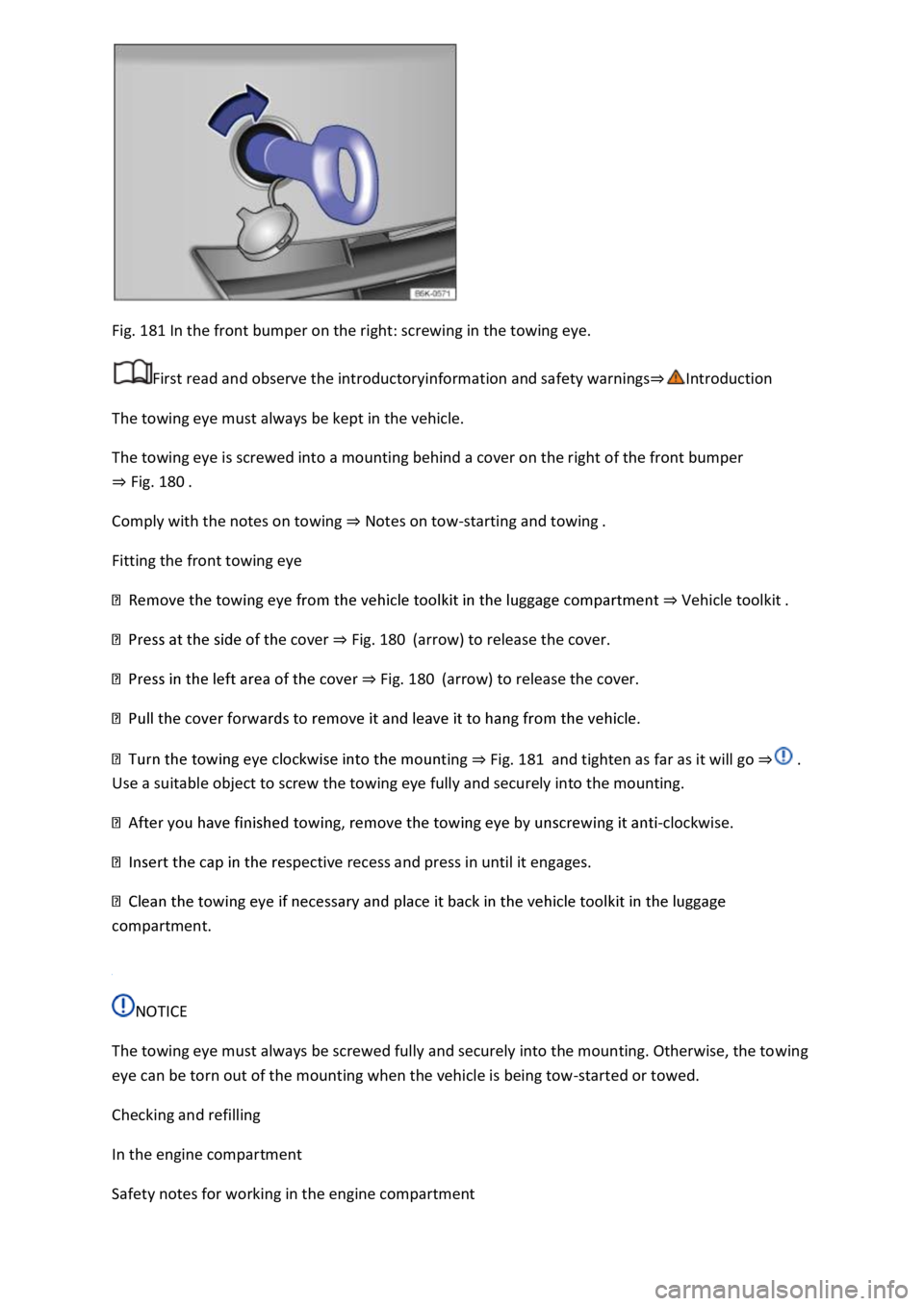
Fig. 181 In the front bumper on the right: screwing in the towing eye.
First read and observe the introductoryinformation and safety warnings⇒Introduction
The towing eye must always be kept in the vehicle.
The towing eye is screwed into a mounting behind a cover on the right of the front bumper
⇒ Fig. 180 .
Comply with the notes on towing ⇒ Notes on tow-starting and towing .
Fitting the front towing eye
⇒ Vehicle toolkit .
e cover ⇒ Fig. 180 (arrow) to release the cover.
⇒ Fig. 180 (arrow) to release the cover.
ting ⇒ Fig. 181 and tighten as far as it will go ⇒ .
Use a suitable object to screw the towing eye fully and securely into the mounting.
-clockwise.
spective recess and press in until it engages.
compartment.
NOTICE
The towing eye must always be screwed fully and securely into the mounting. Otherwise, the towing
eye can be torn out of the mounting when the vehicle is being tow-started or towed.
Checking and refilling
In the engine compartment
Safety notes for working in the engine compartment