2021 RAM PROMASTER CITY ESP
[x] Cancel search: ESPPage 2 of 280

WARNING: Operating, servicing and maintaining a passenger vehicle or off-highway
motor vehicle can expose you to chemicals including engine exhaust, carbon monoxide,
phthalates, and lead, which are known to the State of California to cause cancer and birth defects
or other reproductive harm. To minimize exposure, avoid breathing exhaust, do not idle the
engine except as necessary, service your vehicle in a well-ventilated area and wear gloves or wash
your hands frequently when servicing your vehicle. For more information go to
www.P65Warnings.ca.gov/passenger-vehicle.
This Owner’s Manual illustrates and describes the operation of features and equipment that are either standard or optional on this vehicle. This manual may
also include a description of features and equipment that are no longer available or were not ordered on this vehicle. Please disregard any features and
equipment that are no longer available or were not ordered on this vehicle. FCA US LLC reserves the right to make changes in design and specifications, and/or
make additions to or improvements to its products without imposing any obligation upon itself to install them on products previously manufactured.
With respect to vehicles sold in Canada, the name FCA US LLC shall be deemed to be deleted and the name FCA Canada Inc. used in substitution therefore.
If you are the first registered retail owner of your vehicle, you may obtain a complimentary printed copy of the Warranty Booklet by calling
1-866-726-4636 (U.S.) or 1-800-387-1143 (Canada), or by contacting your dealer.
This Owner’s Manual is intended to familiarize you with the important features of your vehicle. Your most up-to-date Owner’s Manual, Navigation/Uconnect
manuals and Warranty Booklet can be found by visiting the website on the back cover. U.S. residents can purchase replacement kits by visiting
www.techauthority.com and Canadian residents can purchase replacement kits by calling 1-800-387-1143.
The driver’s primary responsibility is the safe operation of the vehicle. Driving while distracted can result in loss of vehicle control, resulting in an accident and
personal injury. FCA US LLC strongly recommends that the driver use extreme caution when using any device or feature that may take their attention off the
road. Use of any electrical devices, such as cellular telephones, computers, portable radios, vehicle navigation or other devices, by the driver while the vehicle
is moving is dangerous and could lead to a serious accident. Texting while driving is also dangerous and should never be done while the vehicle is moving. If you
find yourself unable to devote your full attention to vehicle operation, pull off the road to a safe location and stop your vehicle. Some states or provinces prohibit
the use of cellular telephones or texting while driving. It is always the driver’s responsibility to comply with all local laws.
This Owner’s Manual has been prepared to help you get acquainted with your new Ram brand vehicle and to provide a convenient reference for common
questions.
Not all features shown in this manual may apply to your vehicle. For additional information on accessories to help personalize your vehicle, visit
www.mopar.com/en-us/care/owners-manual.html (U.S.), www.owners.mopar.ca (Canada) or your local Ram brand dealer.
DRIVING AND ALCOHOL
Drunk driving is one of the most frequent causes of accidents. Your driving ability can be seriously
impaired with blood alcohol levels far below the legal minimum. If you are drinking, don’t drive. Ride with
a designated non-drinking driver, call a cab, a friend or use public transportation.
WARNING
Driving after drinking can lead to an accident. Your perceptions are less sharp, your reflexes are slower
and your judgment is impaired when you have been drinking. Never drink and then drive.
Page 6 of 280

4
MULTIMEDIA
UCONNECT SYSTEMS ..........................................86
CYBERSECURITY ..................................................86
UCONNECT SETTINGS .........................................87 Uconnect 3/3 NAV Settings ........................ 87
UCONNECT INTRODUCTION.................................97
Identifying Your Radio ................................. 97
Safety And General Information ................. 99
UCONNECT MODES ........................................... 100
Radio Mode ................................................100
Media Mode ...............................................107Phone Mode ..............................................109
NAVIGATION MODE — IF EQUIPPED ................ 121
Operating Navigation Mode —
If Equipped .................................................121
STEERING WHEEL AUDIO CONTROLS — IF
EQUIPPED ........................................................... 142
Radio Operation .........................................142
Media Mode ...............................................142
RAM TELEMATICS - IF EQUIPPED .................... 142
Ram Telematics General Information ......143
RADIO OPERATION AND MOBILE PHONES.... 143
Regulatory And Safety Information........... 144
SAFETY
SAFETY FEATURES ............................................ 145 Four-Wheel Anti-Lock Brake
System (ABS) ..............................................145 Electronic Brake Control (EBC) System ...146 AUXILIARY DRIVING SYSTEMS.........................149
Tire Pressure Monitoring
System (TPMS) ........................................... 149
OCCUPANT RESTRAINT SYSTEMS .................. 153
Occupant Restraint Systems .................... 153
Important Safety Precautions ................... 153
Seat Belt Systems ..................................... 154
Supplemental Restraint Systems (SRS)... 161
Child Restraints ......................................... 170
Transporting Pets ...................................... 184
SAFETY TIPS ....................................................... 185
Transporting Passengers .......................... 185Exhaust Gas .............................................. 185
Safety Checks You Should Make Inside
The Vehicle ................................................ 185 Periodic Safety Checks You Should Make
Outside The Vehicle ................................... 187
IN CASE OF EMERGENCY
HAZARD WARNING FLASHERS........................188
FUSES ..................................................................188
General Information .................................. 188Underhood Fuses ...................................... 189
Interior Fuses ............................................. 192
Central Unit Fuse Panel............................. 193 JACKING AND TIRE CHANGING ...................... 194
Jack Location — If Equipped ..................... 194
Removing The Spare Tire — If Equipped .. 194Preparations For Jacking ......................... 196
Jacking Instructions................................... 197
Vehicles With Alloy Wheels ....................... 200Vehicles Equipped With Wheel Covers .... 201
TIRE SERVICE KIT — IF EQUIPPED .................. 202
Tire Service Kit Storage............................. 202
Tire Service Kit Usage ............................... 202
JUMP STARTING ................................................ 204
Preparations For Jump Starting ................ 205
Jump Starting Procedure .......................... 206
IF YOUR ENGINE OVERHEATS ......................... 207
IGNITION KEY REMOVAL OVERRIDE ............... 208
GEAR SELECTOR OVERRIDE ............................ 209
FREEING A STUCK VEHICLE ............................ 209
TOWING A DISABLED VEHICLE ........................ 211
ENHANCED ACCIDENT RESPONSE SYSTEM
(EARS) ................................................................ 212
EVENT DATA RECORDER (EDR) ....................... 212
BULB REPLACEMENT ........................................ 213 Replacement Bulbs ................................... 213
Replacing Exterior Bulbs ........................... 214
Replacing Interior Bulbs ............................ 215
21_VM_OM_EN_USC_t.book Page 4
Page 23 of 280

GETTING TO KNOW YOUR VEHICLE21
HEAD RESTRAINTS
Head restraints are designed to reduce the risk
of injury by restricting head movement in the
event of a rear impact. Head restraints should
be adjusted so that the top of the head restraint
is located above the top of your ear.
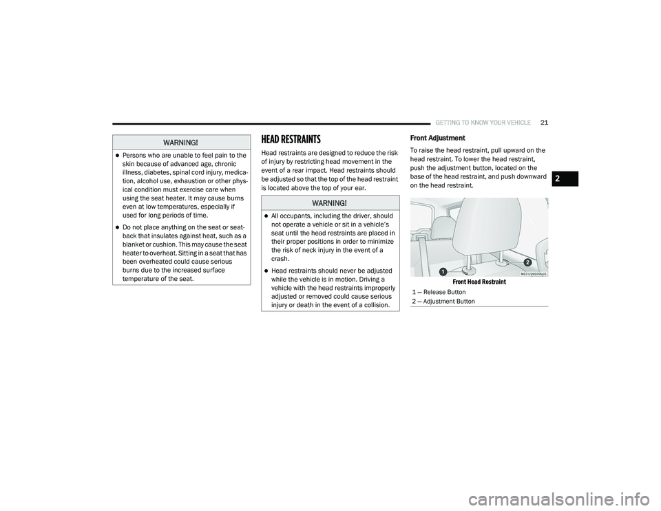
Front Adjustment
To raise the head restraint, pull upward on the
head restraint. To lower the head restraint,
push the adjustment button, located on the
base of the head restraint, and push downward
on the head restraint.
Front Head Restraint
WARNING!
Persons who are unable to feel pain to the
skin because of advanced age, chronic
illness, diabetes, spinal cord injury, medica -
tion, alcohol use, exhaustion or other phys -
ical condition must exercise care when
using the seat heater. It may cause burns
even at low temperatures, especially if
used for long periods of time.
Do not place anything on the seat or seat -
back that insulates against heat, such as a
blanket or cushion. This may cause the seat
heater to overheat. Sitting in a seat that has
been overheated could cause serious
burns due to the increased surface
temperature of the seat.
WARNING!
All occupants, including the driver, should
not operate a vehicle or sit in a vehicle’s
seat until the head restraints are placed in
their proper positions in order to minimize
the risk of neck injury in the event of a
crash.
Head restraints should never be adjusted
while the vehicle is in motion. Driving a
vehicle with the head restraints improperly
adjusted or removed could cause serious
injury or death in the event of a collision.
1 — Release Button
2 — Adjustment Button
2
21_VM_OM_EN_USC_t.book Page 21
Page 31 of 280

GETTING TO KNOW YOUR VEHICLE29
INTERIOR LIGHTS
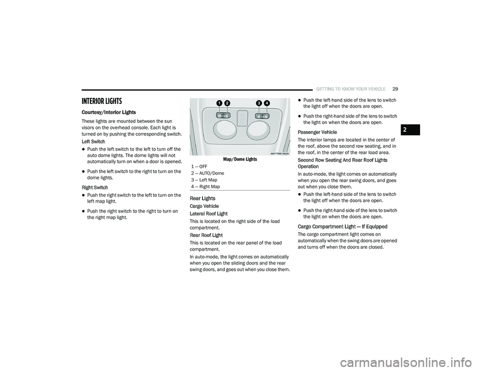
Courtesy/Interior Lights
These lights are mounted between the sun
visors on the overhead console. Each light is
turned on by pushing the corresponding switch.
Left Switch
Push the left switch to the left to turn off the
auto dome lights. The dome lights will not
automatically turn on when a door is opened.
Push the left switch to the right to turn on the
dome lights.
Right Switch
Push the right switch to the left to turn on the
left map light.
Push the right switch to the right to turn on
the right map light.
Map/Dome Lights
Rear Lights
Cargo Vehicle
Lateral Roof Light
This is located on the right side of the load
compartment.
Rear Roof Light
This is located on the rear panel of the load
compartment.
In auto-mode, the light comes on automatically
when you open the sliding doors and the rear
swing doors, and goes out when you close them.
Push the left-hand side of the lens to switch
the light off when the doors are open.
Push the right-hand side of the lens to switch
the light on when the doors are open.
Passenger Vehicle
The interior lamps are located in the center of
the roof, above the second row seating, and in
the roof, in the center of the rear load area.
Second Row Seating And Rear Roof Lights
Operation
In auto-mode, the light comes on automatically
when you open the rear swing doors, and goes
out when you close them.
Push the left-hand side of the lens to switch
the light off when the doors are open.
Push the right-hand side of the lens to switch
the light on when the doors are open.
Cargo Compartment Light — If Equipped
The cargo compartment light comes on
automatically when the swing doors are opened
and turns off when the doors are closed.
1 — OFF
2 — AUTO/Dome
3 — Left Map
4 — Right Map
2
21_VM_OM_EN_USC_t.book Page 29
Page 44 of 280

42GETTING TO KNOW YOUR VEHICLE
(Continued)
To move the crossbars, loosen the
attachments, located at the upper edge of each
crossbar, approximately eight turns using the
anti-theft wrench provided with the Mopar
crossbars. Then, move the crossbar to the
desired position, keeping the crossbars parallel
to the rack frame. Once the crossbar is in the
desired position, re-tighten it with the wrench to
lock the crossbar into position.
NOTE:
To help control wind noise when the cross-
bars are not in use, place the front and rear
crossbars approximately 24 inches (61 cm)
apart. Optimal noise reduction can then be
achieved by adjusting the front crossbar
forward or aft using increments of 1 inch
(2.5 cm).
If the crossbar (or any metallic object) is
placed over the satellite radio antenna (if
equipped), you may experience interruption
of satellite radio reception. For improved
satellite radio reception, avoid placing the
rear crossbar over the satellite radio
antenna.
WARNING!
Cargo must be securely tied down before
driving your vehicle. Improperly secured loads
can fly off the vehicle, particularly at high
speeds, resulting in personal injury or
property damage. Follow the roof rack
cautions when carrying cargo on your roof
rack.
CAUTION!
To prevent damage to the roof of your
vehicle, DO NOT carry any loads on the roof
rack without the crossbars deployed. The
load should be secured and placed on top
of the crossbars, not directly on the roof. If
it is necessary to place the load on the roof,
place a blanket or other protective layer
between the load and the roof surface.
To avoid damage to the roof rack and
vehicle, do not exceed the maximum roof
rack load capacity of 150 lb (68 kg). Always
distribute heavy loads as evenly as possible
and secure the load appropriately.
Loads should always be secured to cross -
bars first, with tie down loops used as addi -
tional securing points if needed. Tie loops
are intended as supplementary tie down
points only. Do not use ratcheting mecha -
nisms with the tie loops. Check the straps
and thumb wheels frequently to be sure
that the load remains securely attached.
Long loads that extend over the windshield,
such as wood panels or surfboards, or
loads with large frontal area should be
secured to both the front and rear of the
vehicle.
Travel at reduced speeds and turn corners
carefully when carrying large or heavy loads
on the roof rack. Wind forces, due to
natural causes or nearby truck traffic, can
add sudden upward lift to a load. This is
especially true on large flat loads and may
result in damage to the cargo or your
vehicle.
CAUTION! (Continued)
21_VM_OM_EN_USC_t.book Page 42
Page 55 of 280

GETTING TO KNOW YOUR INSTRUMENT PANEL53
Tire Pressure Monitoring System (TPMS)
Warning Light
The warning light switches on and a
message is displayed to indicate that
the tire pressure is lower than the
recommended value and/or that slow
pressure loss is occurring. In these cases,
optimal tire duration and fuel consumption may
not be guaranteed.
Should one or more tires be in the condition
mentioned above, the display will show the
indications corresponding to each tire.
Each tire, including the spare (if provided),
should be checked monthly when cold and
inflated to the inflation pressure recommended
by the vehicle manufacturer on the vehicle
placard or tire inflation pressure label. If your
vehicle has tires of a different size than the size indicated on the vehicle placard or tire inflation
pressure label, you should determine the
proper tire inflation pressure for those tires.
As an added safety feature, your vehicle has
been equipped with a TPMS that illuminates a
low tire pressure telltale when one or more of
your tires is significantly underinflated.
Accordingly, when the low tire pressure telltale
illuminates, you should stop and check your
tires as soon as possible, and inflate them to
the proper pressure. Driving on a significantly
underinflated tire causes the tire to overheat
and can lead to tire failure. Under-inflation also
reduces fuel efficiency and tire tread life, and
may affect the vehicle’s handling and stopping
ability.
Please note that the TPMS is not a substitute for
proper tire maintenance, and it is the driver’s
responsibility to maintain correct tire pressure,
even if under-inflation has not reached the level
to trigger illumination of the TPMS low tire
pressure telltale.
Your vehicle has also been equipped with a
TPMS malfunction indicator to indicate when
the system is not operating properly. The TPMS
malfunction indicator is combined with the low
tire pressure telltale. When the system detects
a malfunction, the telltale will flash for approximately one minute and then remain
continuously illuminated. This sequence will
continue upon subsequent vehicle start-ups as
long as the malfunction exists. When the
malfunction indicator is illuminated, the system
may not be able to detect or signal low tire
pressure as intended. TPMS malfunctions may
occur for a variety of reasons, including the
installation of replacement or alternate tires or
wheels on the vehicle that prevent the TPMS
from functioning properly. Always check the
TPMS malfunction telltale after replacing one or
more tires or wheels on your vehicle to ensure
that the replacement or alternate tires and
wheels allow the TPMS to continue to function
properly.
CAUTION!
Do not continue driving with one or more flat
tires as handling may be compromised. Stop
the vehicle, avoiding sharp braking and
steering. If a tire puncture occurs, repair
immediately using the dedicated tire repair
kit and contact an authorized dealer as soon
as possible.
3
21_VM_OM_EN_USC_t.book Page 53
Page 57 of 280

GETTING TO KNOW YOUR INSTRUMENT PANEL55
Electronic Stability Control (ESC) Warning
Light — If Equipped
The ESC Indicator Light in the
instrument cluster will come on when
the ignition is placed in the ON/RUN
or MAR/ON/RUN position, and when
ESC is activated. It should go out with the
engine running. If the ESC Indicator Light comes
on continuously with the engine running, a
malfunction has been detected in the ESC
system. If this light remains on after several
ignition cycles, and the vehicle has been driven
several miles (kilometers) at speeds greater
than 30 mph (48 km/h), see your authorized
dealer as soon as possible to have the problem
diagnosed and corrected.
The ESC OFF Indicator Light and the ESC Indi -
cator Light come on momentarily each time
the ignition is placed in the ON/RUN or MAR/
ON/RUN position.
Each time the ignition is turned to ON/RUN or
MAR/ON/RUN, the ESC system will be on,
even if it was turned off previously.
The ESC system will make buzzing or clicking
sounds when it is active. This is normal; the
sounds will stop when ESC becomes inactive.
This light will come on when the vehicle is in
an ESC event.
Electronic Stability Control (ESC) OFF
Warning Light — If Equipped
This warning light indicates the ESC is
off.
Each time the ignition is turned to ON/RUN or
ACC/ON/RUN, the ESC system will be on, even
if it was turned off previously.
Green Indicator Lights
Turn Signal Indicator Lights
When the left or right turn signal is
activated, the turn signal indicator will
flash independently and the
corresponding exterior turn signal
lamps will flash. Turn signals can be activated
when the multifunction lever is moved down
(left) or up (right). NOTE:
A continuous chime will sound if the vehicle is
driven more than 1 mile (1.6 km) with either
turn signal on.
Check for an inoperative outside light bulb if
either indicator flashes at a rapid rate.
Park/Headlight On Indicator Light
This indicator light will illuminate
when the park lights or headlights are
turned on Ú
page 27.
Front Fog Indicator Light — If Equipped
This indicator light will illuminate
when the front fog lights are on
Úpage 27.
Cruise Control Indicator Light — If Equipped
This indicator light will illuminate
when the cruise control is activated
Úpage 68.
NOTE:
There will be no change in the indicator light
when the desired speed is set.
3
21_VM_OM_EN_USC_t.book Page 55
Page 66 of 280
![RAM PROMASTER CITY 2021 Owners Manual
64STARTING AND OPERATING
(Continued)
(Continued)
gear selector to the right (into the DRIVE [D]
position) for access to PARK, REVERSE, and
NEUTRAL.
Gear Selector
Gear Ranges
Do not press the ac RAM PROMASTER CITY 2021 Owners Manual
64STARTING AND OPERATING
(Continued)
(Continued)
gear selector to the right (into the DRIVE [D]
position) for access to PARK, REVERSE, and
NEUTRAL.
Gear Selector
Gear Ranges
Do not press the ac](/manual-img/34/59212/w960_59212-65.png)
64STARTING AND OPERATING
(Continued)
(Continued)
gear selector to the right (into the DRIVE [D]
position) for access to PARK, REVERSE, and
NEUTRAL.
Gear Selector
Gear Ranges
Do not press the accelerator pedal when
shifting out of PARK or NEUTRAL.
NOTE:
After selecting any gear range, wait a moment
to allow the selected gear to engage before
accelerating. This is especially important when
the engine is cold.
PARK (P)
The engine can be started in this range. Never
attempt to use PARK while the vehicle is in
motion. If necessary, apply the parking brake
prior to placing the vehicle in PARK.
When parking on a hill, apply the parking brake
before shifting the transmission to PARK,
otherwise the load on the transmission locking
mechanism may make it difficult to move the
gear selector out of PARK. As an added
precaution, turn the front wheels toward the
curb on a downhill grade and away from the
curb on an uphill grade.
When exiting the vehicle, always:
Apply the parking brake.
Shift the transmission into PARK.
Turn the engine off.
Remove the ignition key.
WARNING!
Never use the PARK position as a substi -
tute for the parking brake. Always apply the
parking brake fully when exiting the vehicle
to guard against vehicle movement and
possible injury or damage.
Your vehicle could move and injure you and
others if it is not in PARK. Check by trying to
move the gear selector out of PARK with the
brake pedal released. Make sure the trans -
mission is in PARK before exiting the vehicle.
It is dangerous to shift out of PARK or
NEUTRAL if the engine speed is higher than
idle speed. If your foot is not firmly pressing
the brake pedal, the vehicle could accel -
erate quickly forward or in reverse. You
could lose control of the vehicle and hit
someone or something. Only shift into gear
when the engine is idling normally and your
foot is firmly pressing the brake pedal.
Unintended movement of a vehicle could
injure those in or near the vehicle. As with
all vehicles, you should never exit a vehicle
while the engine is running. Before exiting a
vehicle always come to a complete stop,
then apply the parking brake, shift the
transmission into PARK, turn the engine off,
and remove the ignition key. Once the key is
removed, the transmission is locked in
PARK, securing the vehicle against
unwanted movement.
WARNING! (Continued)
21_VM_OM_EN_USC_t.book Page 64