Page 193 of 280
IN CASE OF EMERGENCY191
F20 –30 Amp Green Rear Defroster (If Equipped)
F21 –5 Amp TanKey Unlock
F22 –10 Amp RedPrimary ECM Loads
F23 –20 Amp Yellow BSM System
F24 –5 Amp TanBSM System, Positive Key and Steering Angle Sensor
F30 –15 Amp Blue2nd Instrument Panel Power Outlet (Battery)
F83 20 Amp Yellow –Fuel Pump
F84 –15 Amp BlueAT Module
F85 –15 Amp BlueRear Power Outlet 12 Volts (ACC/ON/RUN)
F86 –15 Amp BlueIP Power Outlet 12 Volts (ACC/ON/RUN)
F87 –5 Amp TanIBS
F88 –7.5 Amp Brown External Mirror Defrost (If Equipped)
CavityMaxi Fuse Mini Fuse Description
7
21_VM_OM_EN_USC_t.book Page 191
Page 194 of 280
192IN CASE OF EMERGENCY
Interior Fuses
The interior fuse panel is part of the Body
Control Module (BCM) and is located on the
driver's side under the instrument panel.
Fuse Panel CoverFuse Panel Cavity Locations
CavityMini Fuse Description
F535 Amp Beige KL 30 (+30) - IPC, FTM
F38 20 Amp Yellow Central Doors Locking
F36 15 Amp Blue KL 30 (+30) - TPMS, EOBD, HVAC, Radio, USB, SGW
F43 15 Amp Blue Bi-Directional Washer Pump
F48 20 Amp Yellow Passenger Power Windows
F50 7.5 Amp Brown KL 15 (+15) - Air-Bag
F51 7.5 Amp Brown KL 15 (+15) - External Mirror Adjustment Command, HVAC, RVC, HWB Coils
F37 5 Amp Beige KL 15 (+15) - Brake Pedal Switch (N.O.), IPC, Brake Pedal Switch (N.C.)
F49 5 Amp Beige KL 15 (+15) - PAM, CSS Lighting, TTM, SGW, and Heaters Light, ECM Backlighting
F31 5 Amp Beige KL 15a (INT A) - HWB, MCO
F47 20 Amp Yellow Driver Power Windows
21_VM_OM_EN_USC_t.book Page 192
Page 197 of 280
IN CASE OF EMERGENCY195
2. To access the winch mechanism open the
rear doors of the vehicle to expose the
winch mechanism access hole. Install the
winch extension into the winch mechanism.
Winch LocationJack Tools Winch Location
3. Rotate the wheel wrench handle counter -
clockwise until the spare tire is on the
ground with enough cable slack to allow you
to pull it out from under the vehicle.
Lowering The Spare Tire
NOTE:
The winch mechanism is designed for use with
the winch extension only. Use of an air wrench
or other power tools is not recommended and
can damage the winch.
4. Pull the spare tire out from under the
vehicle to gain access to the spare tire
retainer.
Spare Tire
1 — Wrench Handle
2 — Winch Extension
7
21_VM_OM_EN_USC_t.book Page 195
Page 198 of 280
196IN CASE OF EMERGENCY
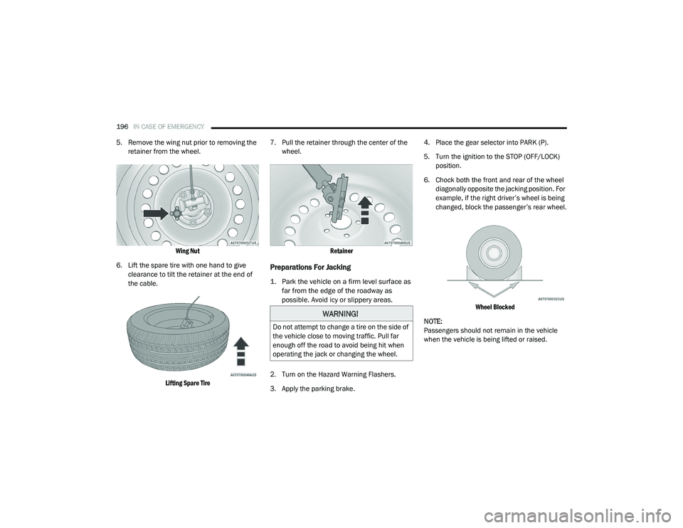
5. Remove the wing nut prior to removing the
retainer from the wheel.
Wing Nut
6. Lift the spare tire with one hand to give clearance to tilt the retainer at the end of
the cable.
Lifting Spare Tire
7. Pull the retainer through the center of the
wheel.
Retainer
Preparations For Jacking
1. Park the vehicle on a firm level surface as far from the edge of the roadway as
possible. Avoid icy or slippery areas.
2. Turn on the Hazard Warning Flashers.
3. Apply the parking brake. 4. Place the gear selector into PARK (P).
5. Turn the ignition to the STOP (OFF/LOCK)
position.
6. Chock both the front and rear of the wheel diagonally opposite the jacking position. For
example, if the right driver’s wheel is being
changed, block the passenger’s rear wheel.
Wheel Blocked
NOTE:
Passengers should not remain in the vehicle
when the vehicle is being lifted or raised.
WARNING!
Do not attempt to change a tire on the side of
the vehicle close to moving traffic. Pull far
enough off the road to avoid being hit when
operating the jack or changing the wheel.
21_VM_OM_EN_USC_t.book Page 196
Page 203 of 280
IN CASE OF EMERGENCY201
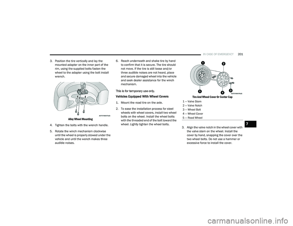
3. Position the tire vertically and lay the
mounted adapter on the inner part of the
rim, using the supplied bolts fasten the
wheel to the adapter using the bolt install
wrench.
Alloy Wheel Mounting
4. Tighten the bolts with the wrench handle.
5. Rotate the winch mechanism clockwise until the wheel is properly stowed under the
vehicle and until the wench makes three
audible noises. 6. Reach underneath and shake tire by hand
to confirm that it is secure. The tire should
not move. If the tire is still loose and/or
three audible noises are not heard, place
and secure damaged wheel into the vehicle
and seek dealer assistance for the winch
mechanism.
This is for temporary use only.
Vehicles Equipped With Wheel Covers
1. Mount the road tire on the axle.
2. To ease the installation process for steel wheels with wheel covers, install two wheel
bolts on the wheel. Install the wheel bolts
with the threaded end of the bolt toward the
wheel. Lightly tighten the wheel bolts.
Tire And Wheel Cover Or Center Cap
3. Align the valve notch in the wheel cover with the valve stem on the wheel. Install the
cover by hand, snapping the cover over the
two wheel bolts. Do not use a hammer or
excessive force to install the cover.1 — Valve Stem
2 — Valve Notch
3 — Wheel Bolt
4 — Wheel Cover
5 — Road Wheel
7
21_VM_OM_EN_USC_t.book Page 201
Page 204 of 280
202IN CASE OF EMERGENCY
4. Install the remaining wheel bolts with the
threaded end of the wheel bolt toward the
wheel. Lightly tighten the wheel bolts.
5. Lower the vehicle to the ground by turning the jack handle counterclockwise.
6. Finish tightening the wheel bolts. Push down on the wrench while holding at the
end of the handle for increased leverage.
Tighten the wheel bolts in a star pattern
until each wheel bolt has been tightened
twice Ú page 255.
7. After 25 miles (40 km) check the wheel bolt torque with a torque wrench to ensure that
all wheel bolts are properly seated against
the wheel.TIRE SERVICE KIT — IF EQUIPPED
Small punctures up to ¼ inch (6 mm) in the tire
tread can be sealed with Tire Service Kit.
Foreign objects (e.g., screws or nails) should not
be removed from the tire. Tire Service Kit can be
used in outside temperatures down to
approximately -4°F (-20°C).
This kit will provide a temporary tire seal,
allowing you to drive your vehicle up to
100 miles (160 km) with a maximum speed of 50 mph (80 km/h).
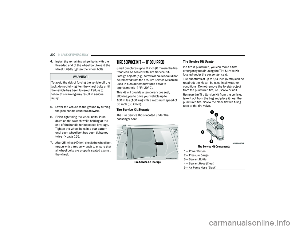
Tire Service Kit Storage
The Tire Service Kit is located under the
passenger seat.
Tire Service Kit Storage
Tire Service Kit Usage
If a tire is punctured, you can make a first
emergency repair using the Tire Service Kit
located under the passenger seat.
Tire punctures of up to 1/4 inch (6 mm) can be
repaired; the kit can be used in all weather
conditions. Do not remove the foreign object
from the punctured tire, i.e., screw or nail.
Remove the Tire Service Kit from the vehicle,
take it out from the bag and place it near the
punctured tire. Screw the clear flexible filling
tube to the tire valve.
Tire Service Kit Components
WARNING!
To avoid the risk of forcing the vehicle off the
jack, do not fully tighten the wheel bolts until
the vehicle has been lowered. Failure to
follow this warning may result in serious
injury.
1 — Power Button
2 — Pressure Gauge
3 — Sealant Bottle
4 — Sealant Hose (Clear)
5 — Air Pump Hose (Black)
21_VM_OM_EN_USC_t.book Page 202
Page 210 of 280
208IN CASE OF EMERGENCY
IGNITION KEY REMOVAL OVERRIDE
This vehicle is equipped with a Key Ignition Park
Interlock which requires the transmission to be
in PARK (P) before the ignition switch can be
turned to the OFF/LOCK (key removal) position.
To remove the key manually, proceed as
follows:
1. Firmly apply the parking brake.
2. Remove the Allen Key located in the rear
cargo area, in the tool bag (if equipped) or
on the left side in the cargo box.
3. Unlock the steering column, pull the tilt/ telescoping control handle down. 4. Pull the steering wheel outward until it is in
the end of the travel position, then lock the
steering column in position, push the
control handle up until fully engaged.
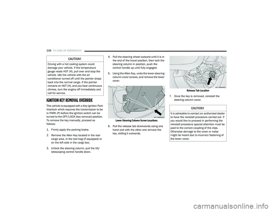
5. Using the Allen Key, undo the lower steering column cover screws, and remove the lower
cover.
Lower Steering Column Screw Locations
6. Pull the release tab downwards using one hand and with the other one remove the
key, sliding it outwards.
Release Tab Location
7. Once the key is removed, reinstall the steering column cover.
CAUTION!
Driving with a hot cooling system could
damage your vehicle. If the temperature
gauge reads HOT (H), pull over and stop the
vehicle. Idle the vehicle with the air
conditioner turned off until the pointer drops
back into the normal range. If the pointer
remains on HOT (H), and you hear continuous
chimes, turn the engine off immediately and
call for service.
CAUTION!
It is advisable to contact an authorized dealer
to have the reinstall procedure carried out. If
you would like to proceed in performing the
reinstall procedure special attention must be
paid to the correct coupling of the clips.
Otherwise damage to the cover or noise
might be heard due to incorrect fastening of
the lower cover.
21_VM_OM_EN_USC_t.book Page 208
Page 211 of 280
IN CASE OF EMERGENCY209
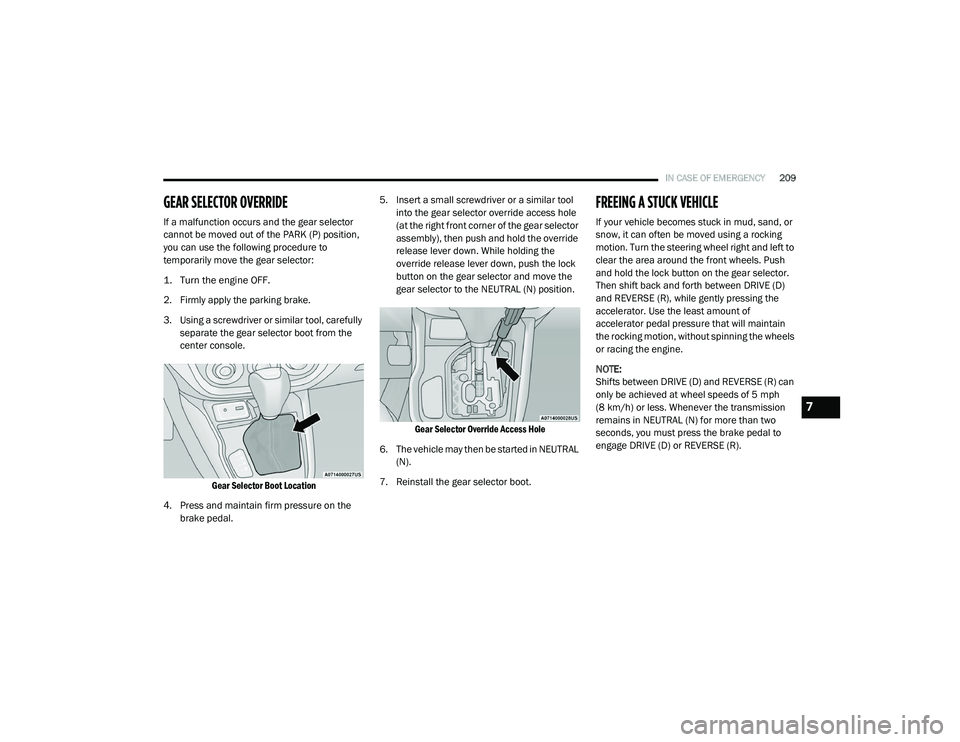
GEAR SELECTOR OVERRIDE
If a malfunction occurs and the gear selector
cannot be moved out of the PARK (P) position,
you can use the following procedure to
temporarily move the gear selector:
1. Turn the engine OFF.
2. Firmly apply the parking brake.
3. Using a screwdriver or similar tool, carefully
separate the gear selector boot from the
center console.
Gear Selector Boot Location
4. Press and maintain firm pressure on the brake pedal. 5. Insert a small screwdriver or a similar tool
into the gear selector override access hole
(at the right front corner of the gear selector
assembly), then push and hold the override
release lever down. While holding the
override release lever down, push the lock
button on the gear selector and move the
gear selector to the NEUTRAL (N) position.
Gear Selector Override Access Hole
6. The vehicle may then be started in NEUTRAL (N).
7. Reinstall the gear selector boot.
FREEING A STUCK VEHICLE
If your vehicle becomes stuck in mud, sand, or
snow, it can often be moved using a rocking
motion. Turn the steering wheel right and left to
clear the area around the front wheels. Push
and hold the lock button on the gear selector.
Then shift back and forth between DRIVE (D)
and REVERSE (R), while gently pressing the
accelerator. Use the least amount of
accelerator pedal pressure that will maintain
the rocking motion, without spinning the wheels
or racing the engine.
NOTE:
Shifts between DRIVE (D) and REVERSE (R) can
only be achieved at wheel speeds of 5 mph
(8 km/h) or less. Whenever the transmission
remains in NEUTRAL (N) for more than two
seconds, you must press the brake pedal to
engage DRIVE (D) or REVERSE (R).
7
21_VM_OM_EN_USC_t.book Page 209