2021 RAM PROMASTER CITY lock
[x] Cancel search: lockPage 37 of 280
GETTING TO KNOW YOUR VEHICLE35
WINDOWS
Power Window Controls — If Equipped
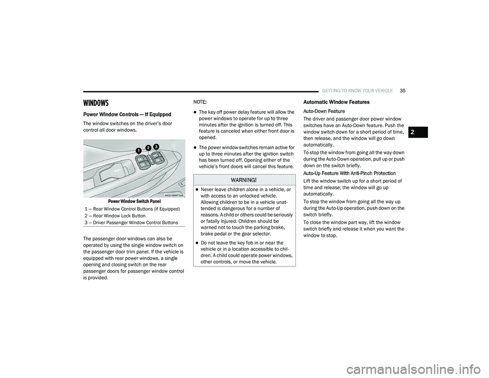
The window switches on the driver’s door
control all door windows.
Power Window Switch Panel
The passenger door windows can also be
operated by using the single window switch on
the passenger door trim panel. If the vehicle is
equipped with rear power windows, a single
opening and closing switch on the rear
passenger doors for passenger window control
is provided. NOTE:
The key off power delay feature will allow the
power windows to operate for up to three
minutes after the ignition is turned off. This
feature is canceled when either front door is
opened.
The power window switches remain active for
up to three minutes after the ignition switch
has been turned off. Opening either of the
vehicle’s front doors will cancel this feature.
Automatic Window Features
Auto-Down Feature
The driver and passenger door power window
switches have an Auto-Down feature. Push the
window switch down for a short period of time,
then release, and the window will go down
automatically.
To stop the window from going all the way down
during the Auto-Down operation, pull up or push
down on the switch briefly.
Auto-Up Feature With Anti-Pinch Protection
Lift the window switch up for a short period of
time and release; the window will go up
automatically.
To stop the window from going all the way up
during the Auto-Up operation, push down on the
switch briefly.
To close the window part way, lift the window
switch briefly and release it when you want the
window to stop.
1 — Rear Window Control Buttons (If Equipped)
2 — Rear Window Lock Button
3 — Driver Passenger Window Control Buttons
WARNING!
Never leave children alone in a vehicle, or
with access to an unlocked vehicle.
Allowing children to be in a vehicle unat
-
tended is dangerous for a number of
reasons. A child or others could be seriously
or fatally injured. Children should be
warned not to touch the parking brake,
brake pedal or the gear selector.
Do not leave the key fob in or near the
vehicle or in a location accessible to chil -
dren. A child could operate power windows,
other controls, or move the vehicle.
2
21_VM_OM_EN_USC_t.book Page 35
Page 39 of 280
GETTING TO KNOW YOUR VEHICLE37
HOOD
Opening
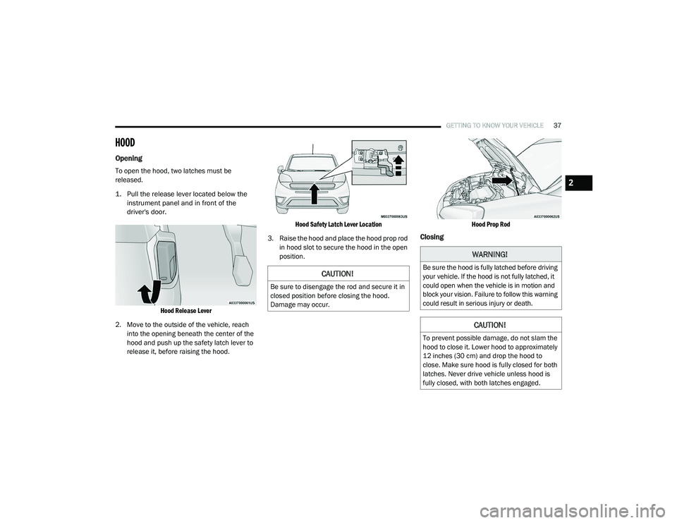
To open the hood, two latches must be
released.
1. Pull the release lever located below the
instrument panel and in front of the
driver's door.
Hood Release Lever
2. Move to the outside of the vehicle, reach into the opening beneath the center of the
hood and push up the safety latch lever to
release it, before raising the hood.
Hood Safety Latch Lever Location
3. Raise the hood and place the hood prop rod in hood slot to secure the hood in the open
position.
Hood Prop Rod
Closing
CAUTION!
Be sure to disengage the rod and secure it in
closed position before closing the hood.
Damage may occur.
WARNING!
Be sure the hood is fully latched before driving
your vehicle. If the hood is not fully latched, it
could open when the vehicle is in motion and
block your vision. Failure to follow this warning
could result in serious injury or death.
CAUTION!
To prevent possible damage, do not slam the
hood to close it. Lower hood to approximately
12 inches (30 cm) and drop the hood to
close. Make sure hood is fully closed for both
latches. Never drive vehicle unless hood is
fully closed, with both latches engaged.
2
21_VM_OM_EN_USC_t.book Page 37
Page 41 of 280
GETTING TO KNOW YOUR VEHICLE39
NOTE:
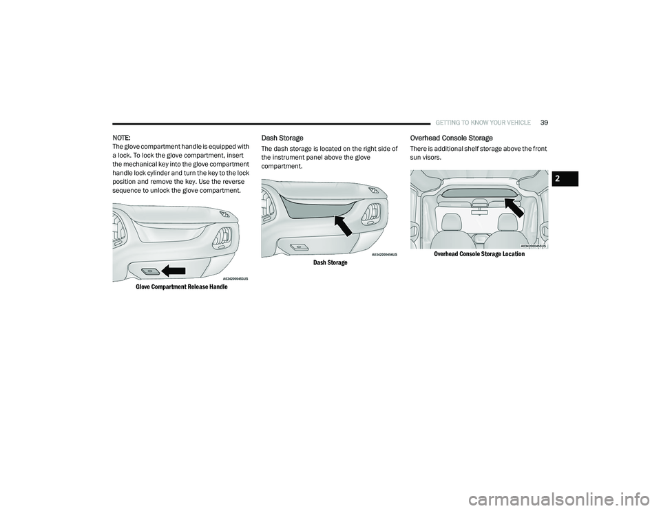
The glove compartment handle is equipped with
a lock. To lock the glove compartment, insert
the mechanical key into the glove compartment
handle lock cylinder and turn the key to the lock
position and remove the key. Use the reverse
sequence to unlock the glove compartment.
Glove Compartment Release Handle
Dash Storage
The dash storage is located on the right side of
the instrument panel above the glove
compartment.
Dash Storage
Overhead Console Storage
There is additional shelf storage above the front
sun visors.
Overhead Console Storage Location
2
21_VM_OM_EN_USC_t.book Page 39
Page 44 of 280
42GETTING TO KNOW YOUR VEHICLE
(Continued)
To move the crossbars, loosen the
attachments, located at the upper edge of each
crossbar, approximately eight turns using the
anti-theft wrench provided with the Mopar
crossbars. Then, move the crossbar to the
desired position, keeping the crossbars parallel
to the rack frame. Once the crossbar is in the
desired position, re-tighten it with the wrench to
lock the crossbar into position.
NOTE:
To help control wind noise when the cross-
bars are not in use, place the front and rear
crossbars approximately 24 inches (61 cm)
apart. Optimal noise reduction can then be
achieved by adjusting the front crossbar
forward or aft using increments of 1 inch
(2.5 cm).
If the crossbar (or any metallic object) is
placed over the satellite radio antenna (if
equipped), you may experience interruption
of satellite radio reception. For improved
satellite radio reception, avoid placing the
rear crossbar over the satellite radio
antenna.
WARNING!
Cargo must be securely tied down before
driving your vehicle. Improperly secured loads
can fly off the vehicle, particularly at high
speeds, resulting in personal injury or
property damage. Follow the roof rack
cautions when carrying cargo on your roof
rack.
CAUTION!
To prevent damage to the roof of your
vehicle, DO NOT carry any loads on the roof
rack without the crossbars deployed. The
load should be secured and placed on top
of the crossbars, not directly on the roof. If
it is necessary to place the load on the roof,
place a blanket or other protective layer
between the load and the roof surface.
To avoid damage to the roof rack and
vehicle, do not exceed the maximum roof
rack load capacity of 150 lb (68 kg). Always
distribute heavy loads as evenly as possible
and secure the load appropriately.
Loads should always be secured to cross -
bars first, with tie down loops used as addi -
tional securing points if needed. Tie loops
are intended as supplementary tie down
points only. Do not use ratcheting mecha -
nisms with the tie loops. Check the straps
and thumb wheels frequently to be sure
that the load remains securely attached.
Long loads that extend over the windshield,
such as wood panels or surfboards, or
loads with large frontal area should be
secured to both the front and rear of the
vehicle.
Travel at reduced speeds and turn corners
carefully when carrying large or heavy loads
on the roof rack. Wind forces, due to
natural causes or nearby truck traffic, can
add sudden upward lift to a load. This is
especially true on large flat loads and may
result in damage to the cargo or your
vehicle.
CAUTION! (Continued)
21_VM_OM_EN_USC_t.book Page 42
Page 48 of 280
46GETTING TO KNOW YOUR INSTRUMENT PANEL
3. Briefly push and release the MENU button
to select the displayed submenu option and
to open the relevant setup menu.
4. Push and release the up or down
arrow button (by single pushes) to select the
new setting for this submenu option.
5. Briefly push and release the MENU button
to store the new setting and go back to the
previously selected submenu option.
6. Push and hold the MENU button to return to
the main menu (short hold) or the main
screen (longer hold).
Change Engine Oil — If Equipped
Your vehicle may be equipped with an engine oil
change indicator system. The “Change Engine
Oil” message will display in the instrument
cluster display. The engine oil change indicator
system is duty cycle based, which means the
engine oil change interval may fluctuate,
dependent upon your personal driving style. Unless reset, this message will continue to
display each time you turn the ignition switch to
the ON/RUN position. To turn off the message
temporarily, push and release the
MENU
button. To reset the oil change indicator system
(after performing the scheduled maintenance),
refer to the following procedure.
1. Turn the ignition switch to the ON position (do not start the engine).
2. Fully push the accelerator pedal slowly, three times, within 10 seconds.
3. Turn the ignition switch to the OFF/LOCK position.
NOTE:
If the indicator message illuminates when you
start the vehicle, the oil change indicator
system did not reset. If necessary, repeat this
procedure.
Instrument Cluster Display Menu Items
Speed Beep
This function is used to set a speed limit (MPH
or km/h); the driver is alerted when this limit is
exceeded.
To set the desired speed limit:
1. Push the
MENU
button briefly. The display
will show the wording (SPEED BEEP) and
the unit (MPH) or (km/h) previously set.
2. If the function is on, push and release the up or down arrow button to select the
required speed limit and then push MENU
to confirm.
NOTE:
The speed may be set in the range from 20 to
125 mph (30 to 200 km/h) according to the previously chosen unit.
The setting will increase/decrease by five units
each time the up or down arrow button is
pushed. Hold down the up or down arrow
button to automatically increase/decrease the
setting rapidly. Complete the adjustment when
you approach the desired value.
21_VM_OM_EN_USC_t.book Page 46
Page 51 of 280

GETTING TO KNOW YOUR INSTRUMENT PANEL49
Values Displayed
Range
This indicates the distance which may be
traveled with the fuel remaining in the tank,
assuming that driving conditions will not
change. The message “----” will appear on the
display in the following cases:
Distance less than 30 miles (or 50 km).
The vehicle is parked for a long time with the
engine running.
NOTE:
The range depends on several factors: driving
style, type of route (freeway, residential, moun -
tain roads, etc.), conditions of use of the vehicle
(load, tire pressure, etc.). Trip planning must
take into account the above notes.
Travel Distance
This value shows the distance covered since the
last reset.
Average Fuel Consumption
This value shows the approximate average
consumption since the last reset.
Current Fuel Consumption
This indicates the fuel consumption. The value
is constantly updated. The message “----” will
appear on the display if the vehicle is parked
with the engine running.
Average Speed
This value shows the vehicle's average speed as
a function of the overall time elapsed since the
last reset.
Travel Time
This value shows the time elapsed since the last
reset.
WARNING LIGHTS AND MESSAGES
The warning/indicator lights will illuminate in
the instrument panel together with a dedicated
message and/or acoustic signal when
applicable. These indications are indicative and
precautionary and as such must not be
considered as exhaustive and/or alternative to
the information contained in the Owner’s
Manual, which you are advised to read carefully
in all cases. Always refer to the information in
this chapter in the event of a failure indication.
All active telltales will display first if applicable.
The system check menu may appear different based upon equipment options and current
vehicle status. Some telltales are optional and
may not appear.
Red Warning Lights
Air Bag Warning Light
This light will turn on for four to eight
seconds as a bulb check when the
ignition is placed in the ON/RUN or
MAR/ON/RUN position. If the light is
either not on during startup, stays on, or turns
on while driving, have the system inspected by
an authorized dealer as soon as possible. This
light will illuminate with a single chime when a
fault with the Air Bag Warning Light has been
detected, it will stay on until the fault is cleared.
If the light comes on intermittently or remains
on while driving, have an authorized dealer
service the vehicle immediately.
Brake Warning Light
This warning light monitors various
brake functions, including brake fluid
level and parking brake application. If
the brake light turns on it may
indicate that the parking brake is applied, that
the brake fluid level is low, or that there is a
problem with the Anti-Lock Brake System
reservoir.
3
21_VM_OM_EN_USC_t.book Page 49
Page 52 of 280

50GETTING TO KNOW YOUR INSTRUMENT PANEL
If the light remains on when the parking brake
has been disengaged, and the fluid level is at
the full mark on the master cylinder reservoir, it
indicates a possible brake hydraulic system
malfunction or that a problem with the Brake
Booster has been detected by the Anti-Lock
Brake System (ABS) / Electronic Stability
Control (ESC) system. In this case, the light will
remain on until the condition has been
corrected. If the problem is related to the brake
booster, the ABS pump will run when applying
the brake, and a brake pedal pulsation may be
felt during each stop.
The dual brake system provides a reserve
braking capacity in the event of a failure to a
portion of the hydraulic system. A leak in either
half of the dual brake system is indicated by the
Brake Warning Light, which will turn on when
the brake fluid level in the master cylinder has
dropped below a specified level.
The light will remain on until the cause is
corrected. NOTE:
The light may flash momentarily during sharp
cornering maneuvers, which change fluid level
conditions. The vehicle should have service
performed, and the brake fluid level checked.
If brake failure is indicated, immediate repair is
necessary.
Vehicles equipped with the Anti-Lock Brake
System (ABS) are also equipped with Electronic
Brake Force Distribution (EBD). In the event of
an EBD failure, the Brake Warning Light will turn
on along with the ABS Light. Immediate repair to
the ABS system is required.
Operation of the Brake Warning Light can be
checked by turning the ignition switch from the
OFF position to the ON/RUN position. The light
should illuminate for approximately two seconds. The light should then turn off unless
the parking brake is applied or a brake fault is
detected. If the light does not illuminate, have
the light inspected by an authorized dealer.
The light also will turn on when the parking
brake is applied with the ignition switch in the
ON/RUN position.
NOTE:
This light shows only that the parking brake is
applied. It does not show the degree of brake
application.
Battery Charge Warning Light
This warning light will illuminate when
the battery is not charging properly. If
it stays on while the engine is running,
there may be a malfunction with the
charging system. Contact an authorized dealer
as soon as possible. This indicates a possible
problem with the electrical system or a related
component.
WARNING!
Driving a vehicle with the red brake light on is
dangerous. Part of the brake system may
have failed. It will take longer to stop the
vehicle. You could have a collision. Have the
vehicle checked immediately.
21_VM_OM_EN_USC_t.book Page 50
Page 54 of 280

52GETTING TO KNOW YOUR INSTRUMENT PANEL
Seat Belt Reminder Warning Light
When the ignition is first placed in the
ON/RUN or MAR/ON/RUN position, if
the driver’s seat belt is unbuckled, a
chime will sound and the light will turn
on. When driving, if the driver or front passenger
seat belt remains unbuckled, the Seat Belt
Reminder Light will flash or remain on
continuously and a chime will sound
Ú page 153.
Transmission Fault Warning Light
This light will illuminate (together with
a message in the instrument cluster
display and a buzzer) to indicate a
transmission fault. Contact an
authorized dealer if the message remains after
restarting the engine.
Engine Oil Level Warning Light
This warning light appears on the
panel when the engine oil level falls
below the minimum recommended
value. Restore the correct engine oil
level or contact your authorized dealer for
service.
Yellow Warning Lights
Anti-Lock Brake System (ABS) Warning Light
This light monitors the ABS. The light
will turn on when the ignition is placed
in the ON/RUN or MAR/ON/RUN
position and may stay on for as long
as four seconds.
If the ABS light remains on or turns on while
driving, then the Anti-Lock portion of the brake
system is not functioning and service is
required. However, the conventional brake system will continue to operate normally if the
brake warning light is not on.
If the ABS light is on, the brake system should
be serviced as soon as possible to restore the
benefits of Anti-Lock Brakes. If the ABS light
does not turn on when the ignition is placed in
the ON/RUN or MAR/ON/RUN position, have
the light inspected by an authorized dealer.
Low Fuel Warning Light
When the fuel level reaches
approximately 2–3 gal (9–11 L) this
light will turn on, and remain on until
fuel is added.
Generic Warning Light
The Generic Warning Light will
illuminate if any of the following
conditions occur: Engine Oil Pressure
Sensor Failure, External Light Failure,
Parking Sensor Failure, Fuel Cut-Off Fail/
Intervention, Generic Failure on Trailer, or Air
Bag telltale recovery.
The telltale will blink in case of an Air Bag
Warning Light Failure. Contact an authorized
dealer immediately for service.
WARNING!
If you continue operating the vehicle when
the Transmission Temperature Warning Light
is illuminated you could cause the fluid to boil
over, come in contact with hot engine or
exhaust components and cause a fire.
CAUTION!
Continuous driving with the Transmission
Temperature Warning Light illuminated will
eventually cause severe transmission
damage or transmission failure.
21_VM_OM_EN_USC_t.book Page 52