2021 RAM PROMASTER CITY change wheel
[x] Cancel search: change wheelPage 4 of 280

2
INTRODUCTION
Symbols Key ............................................................ 7
WARNINGS AND CAUTIONS ................................. 7
VAN CONVERSIONS/CAMPERS ............................ 7
VEHICLE MODIFICATIONS/ALTERATIONS .......... 8
Symbol Glossary ..................................................... 8
GETTING TO KNOW YOUR VEHICLE
KEYS ......................................................................10
Key Fob......................................................... 10
SENTRY KEY ..........................................................12
IGNITION SWITCH ................................................12
VEHICLE SECURITY SYSTEM — IF EQUIPPED ...13
To Arm The System ...................................... 13
To Disarm The System................................. 13
Rearming Of The System............................. 13
Security System Manual Override .............. 13
DOORS ..................................................................14
Power Door Locks ....................................... 14
Auto Unlock Doors ....................................... 14
Sliding Side Door ......................................... 14
Double Rear Swing Doors ........................... 16
Child-Protection Door Lock System ............ 17
SEATS ....................................................................17
Manual Adjustment (Front Seats)............... 18
Folding Rear Seat — If Equipped ................ 20
Heated Seats — If Equipped........................ 20 HEAD RESTRAINTS ............................................. 21
Front Adjustment ......................................... 21
Rear Adjustment — If Equipped .................. 22
Front Removal.............................................. 22
Rear Removal — If Equipped....................... 23
STEERING WHEEL ................................................ 23
Tilt/Telescoping Steering Column .............. 23
UCONNECT VOICE RECOGNITION QUICK
TIPS ........................................................................ 24
Introducing Voice Recognition .................... 24
Get Started ................................................... 24
Basic Voice Commands............................... 24
Additional Information ................................. 24
MIRRORS ............................................................. 25
Inside Rearview Mirror ................................ 25
Outside Mirrors ........................................... 25
Vanity Mirror................................................. 26
EXTERIOR LIGHTS ................................................ 27
Multifunction Lever...................................... 27
Headlights ................................................... 27
Daytime Running Lights (DRLs) —
If Equipped .................................................. 27 High/Low Beam Switch ............................... 28
Flash-To-Pass .............................................. 28
Parking Lights ............................................. 28
Follow Me Home/Headlight Delay .............. 28
Fog Lights — If Equipped ............................ 28
Turn Signals ................................................. 28
Lane Change Assist ..................................... 28
INTERIOR LIGHTS ................................................ 29
Courtesy/Interior Lights .............................. 29 WIPERS AND WASHERS .....................................30
Front Wiper Operation ................................. 30
Rear Wiper Operation — If Equipped .......... 31
CLIMATE CONTROLS ...........................................31
Manual Climate Control Descriptions And
Functions ..................................................... 31 Operating Tips.............................................. 33
WINDOWS ............................................................35
Power Window Controls — If Equipped ...... 35
Automatic Window Features ....................... 35
Power Windows System Initialization......... 36
Window Bar Grates — If Equipped .............. 36
Wind Buffeting ............................................ 36
HOOD .....................................................................37
Opening ........................................................ 37
Closing.......................................................... 37
CARGO AREA FEATURES .....................................38
Rear Cargo Tie-Downs ................................. 38
INTERIOR STORAGE AND EQUIPMENT ..............38
Storage ......................................................... 38
USB Control — If Equipped .......................... 40
Power Outlets .............................................. 40
ROOF RACK — IF EQUIPPED................................41
GETTING TO KNOW YOUR INSTRUMENT PANEL
INSTRUMENT CLUSTER........................................43
Instrument Cluster Descriptions................. 44
21_VM_OM_EN_USC_t.book Page 2
Page 30 of 280

28GETTING TO KNOW YOUR VEHICLE
High/Low Beam Switch
Pull the multifunction lever toward the steering
wheel to switch the headlights to high beams.
Pull the multifunction lever again to turn the low
beams back on.
Flash-To-Pass
You can signal another vehicle with your
headlights by lightly pulling the multifunction
lever toward you. This will cause the high beam
headlights to turn on, and remain on, until the
lever is released.
Parking Lights
These lights can only be turned on with the
ignition in the STOP (OFF/LOCK) position or
removed. Move the end of the multifunction
lever to O (Off) position, and then to the
headlight position.
The indicator light telltale in the instrument
panel comes on. The lights stay on until the next
ignition cycle is performed.
Follow Me Home/Headlight Delay
When this feature is selected, the driver can
choose to have the headlights remain on for a
preset period of time after the engine is turned
off.
Activation
Remove the key or turn the ignition to the STOP
(OFF/LOCK) position, and pull the multifunction
lever toward the steering wheel within two
minutes. Each time the lever is pulled, the
activation of the lights will be extended by
30 seconds. The activation of the lights can be
extended to a maximum of 210 seconds.
Deactivation
Pull the multifunction lever toward the steering
wheel and hold it for more than two seconds.
Fog Lights — If Equipped
The fog light switch is located on the center
stack of the instrument panel, just above the
climate controls. Push the switch once to turn the fog
lights on. Push the switch a second
time to turn the fog lights off.
NOTE:
If the vehicle’s ignition is turned off, the fog
lights will also turn off.
Turn Signals
Move the multifunction lever up or down to
activate the turn signals. The arrows on each
side of the instrument cluster flash to show
proper operation.
NOTE:
If either light remains on and does not flash, or
there is a very fast flash rate, check for a defec -
tive outside light bulb.
Lane Change Assist
Lightly push the multifunction lever up or down,
without moving beyond the detent, and the turn
signal will flash five times then automatically
turn off.
21_VM_OM_EN_USC_t.book Page 28
Page 34 of 280
32GETTING TO KNOW YOUR VEHICLE
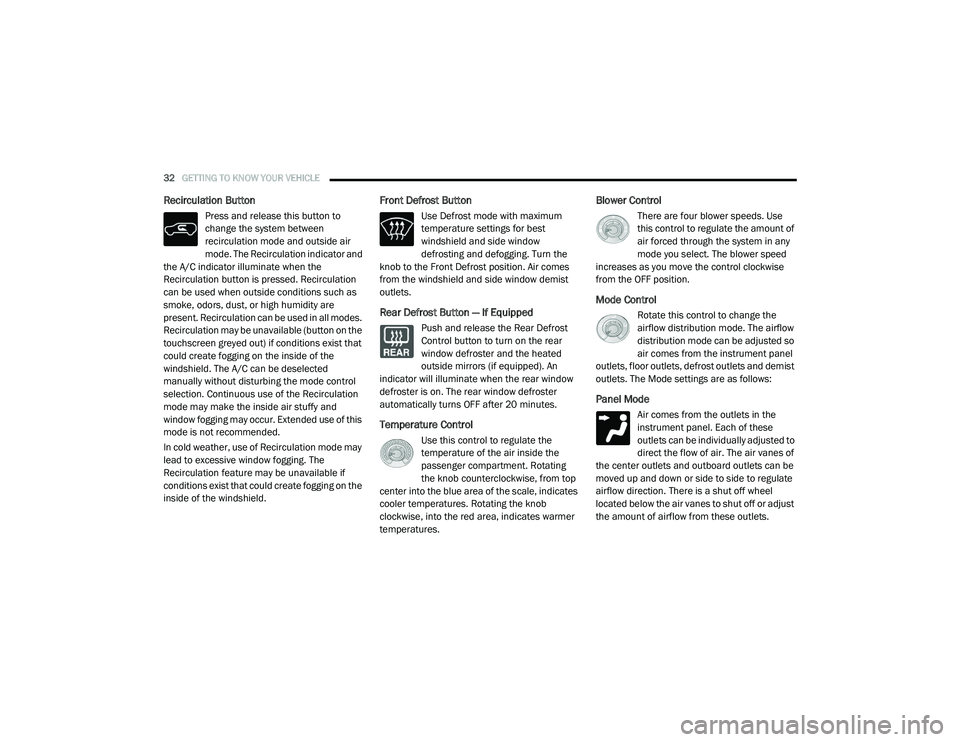
Recirculation Button
Press and release this button to
change the system between
recirculation mode and outside air
mode. The Recirculation indicator and
the A/C indicator illuminate when the
Recirculation button is pressed. Recirculation
can be used when outside conditions such as
smoke, odors, dust, or high humidity are
present. Recirculation can be used in all modes.
Recirculation may be unavailable (button on the
touchscreen greyed out) if conditions exist that
could create fogging on the inside of the
windshield. The A/C can be deselected
manually without disturbing the mode control
selection. Continuous use of the Recirculation
mode may make the inside air stuffy and
window fogging may occur. Extended use of this
mode is not recommended.
In cold weather, use of Recirculation mode may
lead to excessive window fogging. The
Recirculation feature may be unavailable if
conditions exist that could create fogging on the
inside of the windshield.
Front Defrost Button
Use Defrost mode with maximum
temperature settings for best
windshield and side window
defrosting and defogging. Turn the
knob to the Front Defrost position. Air comes
from the windshield and side window demist
outlets.
Rear Defrost Button — If Equipped
Push and release the Rear Defrost
Control button to turn on the rear
window defroster and the heated
outside mirrors (if equipped). An
indicator will illuminate when the rear window
defroster is on. The rear window defroster
automatically turns OFF after 20 minutes.
Temperature Control
Use this control to regulate the
temperature of the air inside the
passenger compartment. Rotating
the knob counterclockwise, from top
center into the blue area of the scale, indicates
cooler temperatures. Rotating the knob
clockwise, into the red area, indicates warmer
temperatures.
Blower Control
There are four blower speeds. Use
this control to regulate the amount of
air forced through the system in any
mode you select. The blower speed
increases as you move the control clockwise
from the OFF position.
Mode Control
Rotate this control to change the
airflow distribution mode. The airflow
distribution mode can be adjusted so
air comes from the instrument panel
outlets, floor outlets, defrost outlets and demist
outlets. The Mode settings are as follows:
Panel Mode
Air comes from the outlets in the
instrument panel. Each of these
outlets can be individually adjusted to
direct the flow of air. The air vanes of
the center outlets and outboard outlets can be
moved up and down or side to side to regulate
airflow direction. There is a shut off wheel
located below the air vanes to shut off or adjust
the amount of airflow from these outlets.
21_VM_OM_EN_USC_t.book Page 32
Page 69 of 280
STARTING AND OPERATING67
Torque Converter Clutch
A feature designed to improve fuel economy
has been included in the automatic
transmission on your vehicle. A clutch within the
torque converter engages automatically at
calibrated speeds. This may result in a slightly
different feeling or response during normal
operation in the upper gears. When the vehicle
speed drops or during some accelerations, the
clutch automatically disengages.
NOTE:
The torque converter clutch will not engage until
the transmission fluid is warm [usually after 1 to
3 miles (2 to 5 km) of driving]. Because the
engine speed is higher when the torque
converter clutch is not engaged, it may seem as
if the transmission is not shifting properly when
cold. This is normal. The torque converter clutch
will function normally once the transmission is
sufficiently warm.
Electronic Range Select (ERS) Operation
The Electronic Range Select (ERS) shift control
allows the driver to limit the highest available
gear. For example, if you set the transmission
gear limit to fifth gear, the transmission will not
shift above fifth gear, but will shift through the
lower gears normally. You can switch between DRIVE and ERS mode
at any vehicle speed. When the gear selector is
in the DRIVE position, the transmission will
operate automatically, shifting between all
available gears.
Moving the gear selector to the ERS position
(beside DRIVE) will activate ERS mode, display
the current gear in the instrument cluster, and
set that gear as the top available gear. Once in
ERS mode, moving the gear selector forward (-)
or rearward (+) will change the top available
gear, which will be displayed in the instrument
cluster.
To exit ERS mode, simply return the gear
selector to the DRIVE position.
NOTE:
To select the proper gear position for maximum
deceleration (engine braking), move the gear
selector into the ERS position, then simply press
and hold it forward (-). The transmission will
shift to the range from which the vehicle can
best be slowed down.
POWER STEERING
The standard power steering system will give
you good vehicle response and increased ease
of maneuverability in tight spaces. The system
will provide mechanical steering capability if
power assist is lost.
If for some reason the power assist is
interrupted, it will still be possible to steer your
vehicle. Under these conditions, you will
observe a substantial increase in steering
effort, especially at very low vehicle speeds and
during parking maneuvers.
WARNING!
Do not downshift for additional engine
braking on a slippery surface. The drive
wheels could lose their grip and the vehicle
could skid, causing a collision or personal
injury.
4
21_VM_OM_EN_USC_t.book Page 67
Page 123 of 280
MULTIMEDIA121
Siri® Eyes Free — If Equipped
When used with your Apple® iPhone®
connected to your vehicle, Siri lets you use your
voice to send text messages, select media,
place phone calls and much more. Siri uses
your natural language to understand what you
mean and responds back to confirm your
requests. The system is designed to keep your
eyes on the road and your hands on the wheel
by letting Siri help you perform useful tasks.
To enable Siri, push and hold, then release the
Uconnect Voice Recognition (VR) button on the
steering wheel. After you hear a double beep,
you can ask Siri to play podcasts and music, get
directions, read text messages, and many other
useful requests.
Bluetooth® Communication Link
Mobile phones may lose connection to the
Uconnect Phone. When this happens, the
connection can generally be re-established by
restarting the mobile phone. Your mobile phone
is recommended to remain in Bluetooth® ON
mode. Power-Up
After switching the ignition key from OFF to
either the ON/RUN or ACC position, or after a
language change, you must wait at least
15 seconds prior to using the system
Ú
page 265.
NAVIGATION MODE — IF EQUIPPED
Operating Navigation Mode — If Equipped
Planning A Route
Using the search bar provides a wide range of
ways to find places and then navigate to them.
You can search for your destination in different
ways:
A specific address
A partial address
A type of place
A zip code
A city to navigate to a city center
A Point of Interest (POI) near your current
location
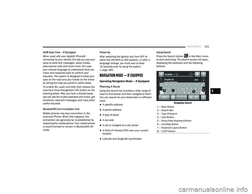
Latitude and longitude coordinates Using Search
Press the Search button in the Main menu
to start searching. The search screen will open,
displaying the keyboard and the following
buttons:
Navigation Search
1 — Back Button
2 — Search Box
3 — Type Of Search
4 — View Button
5 — Show/Hide Keyboard Button
6 — List/Map Button
7 — Keyboard Layout Button
8 — 123?! Button
5
21_VM_OM_EN_USC_t.book Page 121
Page 132 of 280
130MULTIMEDIA
Voice Command — If Equipped
About Voice command
Instead of pressing the touchscreen to control
your navigation system, you can use your voice
to control navigation.
For example, to switch to 2D view, you can say
“2D view”.
To view a list of available commands, press the
“Help” button in the Main menu and then press
“What can I say?”.
Using Voice Control The following example shows how to use voice
control to plan a journey to your Home address:
1. Push the Voice Recognition button on
the steering wheel to turn on the
microphone.
A screen will pop up with examples of com -
mands.
NOTE:
Press the Help button in the Main menu then
press “What can I say?” to see a full list of
commands.
2. When you hear a beep, say a command of your choice. For example, you can say
“Navigate home”.
NOTE:
For accurate results, speak normally without
trying to articulate words in an unnatural way. If
there is excessive road noise, for example, you
may need to speak directly into the microphone.
3. If the command is correct, say “Yes”. NOTE:
If the command is incorrect, say “No” and
repeat the command after you hear the prompt
and tone again. Your navigation system plans a
route from your current location to your destina-
tion. To stop your navigation system from
listening out for further commands, say
“Cancel”.
Guidance View
The guidance view is used to guide you along
the route to your destination. As soon as you
start driving, your navigation system will
immediately start guiding you to your
destination with spoken instructions and visual
instructions on the touchscreen. You can also
see your current location and details along your
route, including 3D buildings in some cities. The
guidance view is normally in 3D. To show a 2D
map with the map moving in your direction of
travel, change the 2D and 3D settings
Ú
page 135.
WARNING!
ALWAYS drive safely with your hands on the
wheel. You have full responsibility and
assume all risks related to the use of the
Uconnect features and applications in this
vehicle. Only use Uconnect when it is safe to
do so. Failure to do so may result in an
accident involving serious injury or death.
21_VM_OM_EN_USC_t.book Page 130
Page 149 of 280
SAFETY147
(Continued)
ESC Activation/Malfunction Indicator Light
And ESC OFF Indicator Light
The ESC Activation/Malfunction
Indicator Light in the instrument
cluster will come on when the ignition
switch is turned to the MAR (ON/RUN)
position for four seconds. If the ESC Activation/
Malfunction Indicator Light comes on
continuously with the engine running, a
malfunction has been detected in the ESC
system. If this light remains on after several
ignition cycles, and the vehicle has been driven
several miles (km) at speeds greater than
30 mph (48 km/h), see an authorized dealer as
soon as possible to have the problem
diagnosed and corrected.
WARNING!
Electronic Stability Control (ESC) cannot
prevent the natural laws of physics from
acting on the vehicle, nor can it increase
the traction afforded by prevailing road
conditions. ESC cannot prevent accidents,
including those resulting from excessive
speed in turns, driving on very slippery
surfaces, or hydroplaning. ESC also cannot
prevent accidents resulting from loss of
vehicle control due to inappropriate driver
input for the conditions. Only a safe, atten -
tive, and skillful driver can prevent acci -
dents. The capabilities of an ESC equipped
vehicle must never be exploited in a reck -
less or dangerous manner which could
jeopardize the user’s safety or the safety of
others.Vehicle modifications, or failure to properly
maintain your vehicle, may change the
handling characteristics of your vehicle,
and may negatively affect the performance
of the ESC system. Changes to the steering
system, suspension, braking system, tire
type and size or wheel size may adversely
affect ESC performance. Improperly
inflated and unevenly worn tires may also
degrade ESC performance. Any vehicle
modification or poor vehicle maintenance
that reduces the effectiveness of the ESC
system can increase the risk of loss of
vehicle control, vehicle rollover, personal
injury and death.
WARNING! (Continued)
6
21_VM_OM_EN_USC_t.book Page 147
Page 150 of 280
148SAFETY
The ESC Activation/Malfunction Indicator Light
(located in the instrument cluster) starts to
flash as soon as the tires lose traction and the
ESC system becomes active. The ESC
Activation/Malfunction Indicator Light also
flashes when TCS is active. If the ESC
Activation/Malfunction Indicator Light begins to
flash during acceleration, ease up on the
accelerator and apply as little throttle as
possible. Be sure to adapt your speed and
driving to the prevailing road conditions.
The ESC OFF Indicator Light indicates
the Electronic Stability Control (ESC)
is in a reduced mode.
NOTE:
The ESC Activation/Malfunction Indicator
Light and the ESC OFF Indicator Light come
on momentarily each time the ignition switch
placed in the ON position.
Each time the ignition is placed in the ON
position, the ESC system will be on even if it
was turned off previously.
Electronic Roll Mitigation (ERM)
ERM anticipates the potential for wheel lift by
monitoring the driver’s steering wheel input and
the speed of the vehicle. When ERM determines
that the rate of change of the steering wheel
angle and vehicle’s speed are sufficient to
potentially cause wheel lift, it then applies the
appropriate brake and may also reduce engine
power to lessen the chance that wheel lift will
occur.
ERM can only reduce the chance of wheel lift
occurring during severe or evasive driving
maneuvers; it cannot prevent wheel lift due to
other factors, such as road conditions, leaving
the roadway, or striking objects or other
vehicles.
Hill Start Assist (HSA)
HSA is designed to assist the driver when
starting a vehicle from a stop on a hill. HSA will
maintain the level of brake pressure the driver
applied for a short period of time after the driver
takes their foot off of the brake pedal. If the
driver does not apply the throttle during this
short period of time, the system will release
brake pressure and the vehicle will roll down the
hill. The system will release brake pressure in
proportion to the amount of throttle applied as
the vehicle starts to move in the intended
direction of travel.
HSA Activation Criteria
The following criteria must be met in order for
HSA to activate:
The vehicle must be stopped.
The vehicle must be on a 5% (approximate)
grade or greater hill.
Gear selection matches vehicle uphill direc -
tion (i.e., vehicle facing uphill is in forward
gear; vehicle backing uphill is in REVERSE
gear).
WARNING!
Many factors, such as vehicle loading, road
conditions and driving conditions, influence
the chance that wheel lift or rollover may
occur. ERM cannot prevent all wheel lift or roll
overs, especially those that involve leaving
the roadway or striking objects or other vehi -
cles. The capabilities of an ERM-equipped
vehicle must never be exploited in a reckless
or dangerous manner which could jeopardize
the user's safety or the safety of others.
21_VM_OM_EN_USC_t.book Page 148