2021 RAM PROMASTER CITY battery
[x] Cancel search: batteryPage 59 of 280

GETTING TO KNOW YOUR INSTRUMENT PANEL57
EMISSIONS INSPECTION AND
MAINTENANCE PROGRAMS
In some localities, it may be a legal requirement
to pass an inspection of your vehicle's
emissions control system. Failure to pass could
prevent vehicle registration.
For states that require an Inspection
and Maintenance (I/M), this check
verifies the Malfunction Indicator
Light (MIL) is functioning and is not on
when the engine is running, and that the OBD II
system is ready for testing.
The OBD ll may not be ready if your vehicle was
recently serviced, recently had a depleted
battery or a battery replacement. If the OBD ll
system should be determined not ready for the
I/M test, your vehicle may fail the test.
Your vehicle has a simple ignition actuated test,
which you can use prior to going to the test
station. To check if your vehicle's OBD II system
is ready, you must do the following:
1. Cycle the ignition switch to the ON position, but do not crank or start the engine.
NOTE:
If you crank or start the engine, you will have to
start this test over.
2. As soon as you cycle the ignition switch to
the ON position, you will see the MIL symbol
come on as part of a normal bulb check.
3. Approximately 15 seconds later, one of two things will happen:
The MIL will flash for about 10 seconds
and then return to being fully illuminated
until you turn OFF the ignition or start the
engine. This means that your vehicle's
OBD II system is not ready and you
should not proceed to the I/M station.
The MIL will not flash at all and will
remain fully illuminated until you place
the ignition in the off position or start the
engine. This means that your vehicle's
OBD II system is ready and you can
proceed to the I/M station. If your OBD II system is not ready,
you should
see an authorized dealer or repair facility. If your
vehicle was recently serviced or had a battery
failure or replacement, you may need to do
nothing more than drive your vehicle as you
normally would in order for your OBD II system
to update. A recheck with the above test routine
may then indicate that the system is now ready.
3
21_VM_OM_EN_USC_t.book Page 57
Page 60 of 280

58
STARTING AND OPERATING
STARTING THE ENGINE
Before starting your vehicle, adjust your seat,
adjust both inside and outside mirrors, and
fasten your seat belts.
Automatic Transmission
The gear selector must be in the PARK (P) or
NEUTRAL (N) position before you can start the
engine. Press the brake pedal before shifting to
any driving gear.
NOTE:
You must press the brake pedal before shifting
out of PARK.
Normal Starting
Turn the ignition switch to the AVV (START)
position and release it when the engine starts.
If the engine fails to start within 10 seconds,
turn the ignition switch to the STOP (OFF/LOCK)
position, wait 10 to 15 seconds, then repeat
this procedure.
Cold Weather Operation
To ensure reliable starting at low temperatures,
use of an externally powered electric engine
block heater (available from an authorized
dealer) is recommended.To prevent possible engine damage while
starting at low temperatures, this vehicle will
inhibit engine cranking when the ambient
temperature is less than -31°F (-35° C) and the
oil temperature sensor reading indicates an
engine block heater has not been used. The
message “plug in engine heater” will be
displayed in the instrument cluster when the
ambient temperature is below -25°F (-32° C) at
the time the engine is shut off as a reminder.
Extended Park Starting
NOTE:
Extended Park condition occurs when the
vehicle has not been started or driven for at
least 30 days.
1. Install a battery charger or jumper cables
to the battery to ensure a full battery
charge during the crank cycle.
2. Place the ignition in the AVV (START) position and release it when the engine
starts.
WARNING!
Never leave children alone in a vehicle, or
with access to an unlocked vehicle.
Allowing children to be in a vehicle unat -
tended is dangerous for a number of
reasons. A child or others could be seriously
or fatally injured. Children should be
warned not to touch the parking brake,
brake pedal or the transmission gear
selector.
Do not leave the key fob in or near the
vehicle (or in a location accessible to chil -
dren). A child could operate power
windows, other controls, or move the
vehicle.
21_VM_OM_EN_USC_t.book Page 58
Page 61 of 280

STARTING AND OPERATING59
3. If the engine fails to start within ten
seconds, place the ignition in the STOP
(OFF/LOCK) position, wait five seconds to
allow the starter to cool, then repeat the
Extended Park Starting procedure.
4. If the engine fails to start after eight attempts, allow the starter to cool for at
least 10 minutes, then repeat the
procedure.
If Engine Fails To Start
If the engine fails to start after you have
followed the “Normal Starting” or “Extreme Cold
Weather” procedure, and has not experienced
an extended park condition as identified in
“Extended Park Starting” procedure, it may be
flooded. Push the accelerator pedal all the way
to the floor and hold it there. Crank the engine
for no more than 15 seconds. This should clear
any excess fuel in case the engine is flooded. Leave the ignition key in the MAR (ON/RUN)
position, release the accelerator pedal and
repeat the “Normal Starting” procedure.
After Starting
The idle speed is controlled automatically, and
it will decrease as the engine warms up.
ENGINE BLOCK HEATER — IF EQUIPPED
The engine block heater warms the engine and
permits quicker starts in cold weather.
Connect the cord to a 110-115 Volt AC electrical
outlet with a grounded, three-wire extension
cord.
For ambient temperatures below 0°F (-18°C),
the engine block heater is recommended. For
ambient temperatures below -20°F (-29°C),
the engine block heater is required.
The engine block heater cord is routed under
the hood, behind to the driver’s side headlamp.
Follow the steps below to properly use the
engine block heater:
CAUTION!
To prevent damage to the starter, do not
crank continuously for more than 10 seconds
at a time. Wait 10 to 15 seconds before trying
again.
WARNING!
Never pour fuel or other flammable liquid
into the throttle body air inlet opening in an
attempt to start the vehicle. This could
result in flash fire causing serious personal
injury.
Do not attempt to push or tow your vehicle
to get it started. Vehicles equipped with an
automatic transmission cannot be started
this way. Unburned fuel could enter the
catalytic converter and once the engine has
started, ignite and damage the converter
and vehicle.
If the vehicle has a discharged battery,
booster cables may be used to obtain a
start from a booster battery or the battery in
another vehicle. This type of start can be
dangerous if done improperly
Úpage 204.
CAUTION!
To prevent damage to the starter, do not
continuously crank the engine for more than
25 seconds at a time. Wait 60 seconds
before trying again.
4
21_VM_OM_EN_USC_t.book Page 59
Page 84 of 280

82STARTING AND OPERATING
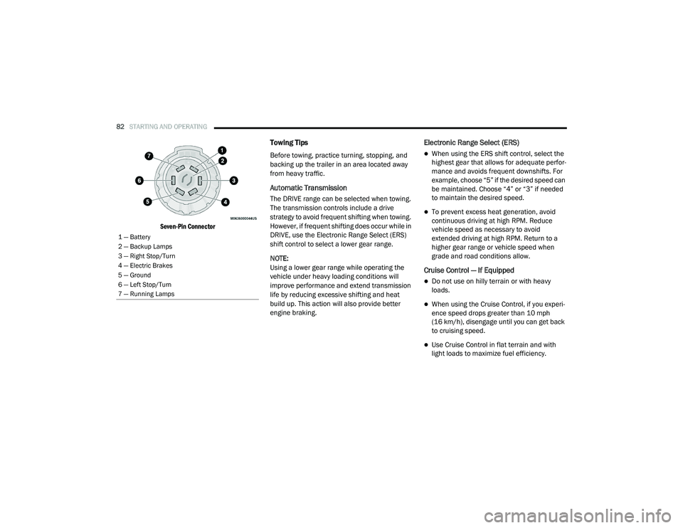
Seven-Pin Connector
Towing Tips
Before towing, practice turning, stopping, and
backing up the trailer in an area located away
from heavy traffic.
Automatic Transmission
The DRIVE range can be selected when towing.
The transmission controls include a drive
strategy to avoid frequent shifting when towing.
However, if frequent shifting does occur while in
DRIVE, use the Electronic Range Select (ERS)
shift control to select a lower gear range.
NOTE:
Using a lower gear range while operating the
vehicle under heavy loading conditions will
improve performance and extend transmission
life by reducing excessive shifting and heat
build up. This action will also provide better
engine braking.
Electronic Range Select (ERS)
When using the ERS shift control, select the
highest gear that allows for adequate perfor -
mance and avoids frequent downshifts. For
example, choose “5” if the desired speed can
be maintained. Choose “4” or “3” if needed
to maintain the desired speed.
To prevent excess heat generation, avoid
continuous driving at high RPM. Reduce
vehicle speed as necessary to avoid
extended driving at high RPM. Return to a
higher gear range or vehicle speed when
grade and road conditions allow.
Cruise Control — If Equipped
Do not use on hilly terrain or with heavy
loads.
When using the Cruise Control, if you experi -
ence speed drops greater than 10 mph
(16 km/h), disengage until you can get back
to cruising speed.
Use Cruise Control in flat terrain and with
light loads to maximize fuel efficiency.
1 — Battery
2 — Backup Lamps
3 — Right Stop/Turn
4 — Electric Brakes
5 — Ground
6 — Left Stop/Turn
7 — Running Lamps
21_VM_OM_EN_USC_t.book Page 82
Page 163 of 280

SAFETY161
Supplemental Restraint Systems (SRS)
Some of the safety features described in this
section may be standard equipment on some
models, or may be optional equipment on
others. If you are not sure, ask an authorized
dealer.
The air bag system must be ready to protect you
in a collision. The Occupant Restraint Controller
(ORC) monitors the internal circuits and
interconnecting wiring associated with the
electrical Air Bag System Components. Your
vehicle may be equipped with the following Air
Bag System Components:
Air Bag System Components
Occupant Restraint Controller (ORC)
Air Bag Warning Light
Steering Wheel and Column
Instrument Panel
Knee Impact Bolsters
Driver and Front Passenger Air Bags
Seat Belt Buckle Switch
Supplemental Side Air Bags
Supplemental Knee Air Bags
Front and Side Impact Sensors
Seat Belt Pretensioners
Air Bag Warning Light
The Occupant Restraint Controller
(ORC) monitors the readiness of the
electronic parts of the air bag system
whenever the ignition switch is in the
AVV/START or MAR/ACC/ON/RUN position. If
the ignition switch is in the STOP/OFF/LOCK
position the air bag system is not on and the air
bags will not inflate. The ORC contains a backup power supply
system that may deploy the air bag system even
if the battery loses power or it becomes
disconnected prior to deployment.
The ORC turns on the Air Bag Warning Light in
the instrument panel for approximately four to
eight seconds for a self-check when the ignition
switch is in the MAR/ACC/ON/RUN position.
After the self-check, the Air Bag Warning Light
will turn off. If the ORC detects a malfunction in
any part of the system, it turns on the Air Bag
Warning Light, either momentarily or
continuously. A single chime will sound to alert
you if the light comes on again after initial
startup.
The ORC also includes diagnostics that will
illuminate the instrument panel Air Bag Warning
Light if a malfunction is detected that could
affect the air bag system. The diagnostics also
record the nature of the malfunction. While the
air bag system is designed to be maintenance
free, if any of the following occurs, have an
authorized dealer service the air bag system
immediately.
Failure to replace the seat belt assembly
could increase the risk of injury in colli
-
sions.
Do not use the Automatic Locking Mode to
restrain occupants who are wearing the
seat belt or children who are using booster
seats. The locked mode is only used to
install rear-facing or forward-facing child
restraints that have a harness for
restraining the child.
WARNING! (Continued)
6
21_VM_OM_EN_USC_t.book Page 161
Page 170 of 280

168SAFETY
Enhanced Accident Response System
In the event of an impact, if the communication
network remains intact, and the power remains
intact, depending on the nature of the event,
the Occupant Restraint Controller (ORC) will
determine whether to have the Enhanced
Accident Response System perform the
following functions:
Cut off fuel to the engine (if equipped)
Cut off battery power to the electric motor (if
equipped)
Flash hazard lights as long as the battery has
power
Turn on the interior lights, which remain on
as long as the battery has power or for
15 minutes from the intervention of the
Enhanced Accident Response System
Unlock the power door locks
Your vehicle may also be designed to perform
any of these other functions in response to the
Enhanced Accident Response System:
Turn off the Fuel Filter Heater, Turn off the
HVAC Blower Motor, Close the HVAC Circula -
tion Door
Cut off battery power to the:
Engine
Electric Motor (if equipped)
Electric Power Steering
Brake booster
Electric park brake
Automatic transmission gear selector
Horn
Front wiper
Headlamp washer pump
NOTE:
After an accident, remember to cycle the igni -
tion to the STOP/OFF position and remove the
key from the ignition switch to avoid draining
the battery. Carefully check the vehicle for fuel
leaks in the engine compartment and on the
ground near the engine compartment and fuel
tank before resetting the system and starting
the engine. If there are no fuel leaks or damage
to the vehicle electrical devices (e.g. headlights)
after an accident, reset the system by following
the procedure described below. If you have any
doubt, contact an authorized dealer.
Enhanced Accident Response System Reset
Procedure
In order to reset the Enhanced Accident
Response System functions after an event, the
ignition switch must be changed from ignition
AVV/START or MAR/RUN to ignition STOP/OFF.
Carefully check the vehicle for fuel leaks in the
engine compartment and on the ground near
the engine compartment and fuel tank before
resetting the system and starting the engine.
After a crash, if the vehicle will not start after
performing the reset procedure, the vehicle
must be towed to an authorized dealer to be
inspected and to have the Enhanced Accident
Response System reset.
21_VM_OM_EN_USC_t.book Page 168
Page 190 of 280

188 (Continued)
IN CASE OF EMERGENCY
HAZARD WARNING FLASHERS
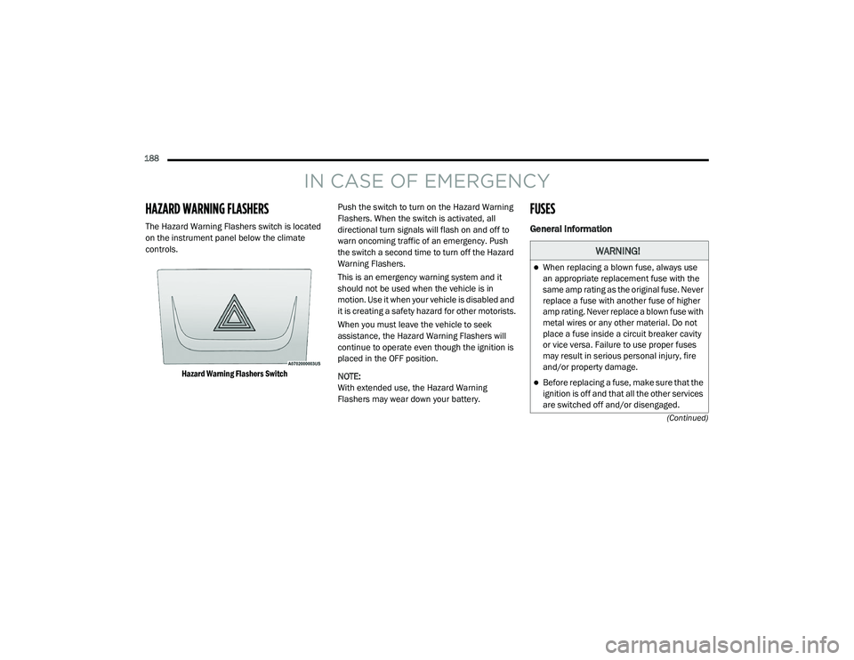
The Hazard Warning Flashers switch is located
on the instrument panel below the climate
controls.
Hazard Warning Flashers Switch
Push the switch to turn on the Hazard Warning
Flashers. When the switch is activated, all
directional turn signals will flash on and off to
warn oncoming traffic of an emergency. Push
the switch a second time to turn off the Hazard
Warning Flashers.
This is an emergency warning system and it
should not be used when the vehicle is in
motion. Use it when your vehicle is disabled and
it is creating a safety hazard for other motorists.
When you must leave the vehicle to seek
assistance, the Hazard Warning Flashers will
continue to operate even though the ignition is
placed in the OFF position.
NOTE:
With extended use, the Hazard Warning
Flashers may wear down your battery.
FUSES
General Information
WARNING!
When replacing a blown fuse, always use
an appropriate replacement fuse with the
same amp rating as the original fuse. Never
replace a fuse with another fuse of higher
amp rating. Never replace a blown fuse with
metal wires or any other material. Do not
place a fuse inside a circuit breaker cavity
or vice versa. Failure to use proper fuses
may result in serious personal injury, fire
and/or property damage.
Before replacing a fuse, make sure that the
ignition is off and that all the other services
are switched off and/or disengaged.
21_VM_OM_EN_USC_t.book Page 188
Page 191 of 280

IN CASE OF EMERGENCY189
The fuses protect electrical systems against
excessive current.
When a device does not work, you must check
the fuse element inside the blade fuse for a
break/melt. Also, please be aware that when using power
outlets for extended periods of time with the
engine off may result in vehicle battery
discharge.
Blade Fuses
Underhood Fuses
The Front Distribution Unit is located on the
right side of the engine compartment, next to
the battery. To access the fuses, remove
fasteners and remove the cover.
Front Distribution Unit
The ID number of the electrical component
corresponding to each fuse can be found on the
back of the cover.If the replaced fuse blows again, contact an
authorized dealer.
If a general protection fuse for safety
systems (air bag system, braking system),
power unit systems (engine system, trans -
mission system) or steering system blows,
contact an authorized dealer.
CAUTION!
If it is necessary to wash the engine
compartment, take care not to directly hit the
fuse box, and the windshield wiper motors
with water.
WARNING! (Continued)
1 — Fuse Element
2 — Blade Fuse with a good/functional fuse ele -
ment
3 — Blade fuse with a bad/not functional fuse el -
ement (blown fuse)
7
21_VM_OM_EN_USC_t.book Page 189