2021 RAM PROMASTER CITY ECO mode
[x] Cancel search: ECO modePage 6 of 280

4
MULTIMEDIA
UCONNECT SYSTEMS ..........................................86
CYBERSECURITY ..................................................86
UCONNECT SETTINGS .........................................87 Uconnect 3/3 NAV Settings ........................ 87
UCONNECT INTRODUCTION.................................97
Identifying Your Radio ................................. 97
Safety And General Information ................. 99
UCONNECT MODES ........................................... 100
Radio Mode ................................................100
Media Mode ...............................................107Phone Mode ..............................................109
NAVIGATION MODE — IF EQUIPPED ................ 121
Operating Navigation Mode —
If Equipped .................................................121
STEERING WHEEL AUDIO CONTROLS — IF
EQUIPPED ........................................................... 142
Radio Operation .........................................142
Media Mode ...............................................142
RAM TELEMATICS - IF EQUIPPED .................... 142
Ram Telematics General Information ......143
RADIO OPERATION AND MOBILE PHONES.... 143
Regulatory And Safety Information........... 144
SAFETY
SAFETY FEATURES ............................................ 145 Four-Wheel Anti-Lock Brake
System (ABS) ..............................................145 Electronic Brake Control (EBC) System ...146 AUXILIARY DRIVING SYSTEMS.........................149
Tire Pressure Monitoring
System (TPMS) ........................................... 149
OCCUPANT RESTRAINT SYSTEMS .................. 153
Occupant Restraint Systems .................... 153
Important Safety Precautions ................... 153
Seat Belt Systems ..................................... 154
Supplemental Restraint Systems (SRS)... 161
Child Restraints ......................................... 170
Transporting Pets ...................................... 184
SAFETY TIPS ....................................................... 185
Transporting Passengers .......................... 185Exhaust Gas .............................................. 185
Safety Checks You Should Make Inside
The Vehicle ................................................ 185 Periodic Safety Checks You Should Make
Outside The Vehicle ................................... 187
IN CASE OF EMERGENCY
HAZARD WARNING FLASHERS........................188
FUSES ..................................................................188
General Information .................................. 188Underhood Fuses ...................................... 189
Interior Fuses ............................................. 192
Central Unit Fuse Panel............................. 193 JACKING AND TIRE CHANGING ...................... 194
Jack Location — If Equipped ..................... 194
Removing The Spare Tire — If Equipped .. 194Preparations For Jacking ......................... 196
Jacking Instructions................................... 197
Vehicles With Alloy Wheels ....................... 200Vehicles Equipped With Wheel Covers .... 201
TIRE SERVICE KIT — IF EQUIPPED .................. 202
Tire Service Kit Storage............................. 202
Tire Service Kit Usage ............................... 202
JUMP STARTING ................................................ 204
Preparations For Jump Starting ................ 205
Jump Starting Procedure .......................... 206
IF YOUR ENGINE OVERHEATS ......................... 207
IGNITION KEY REMOVAL OVERRIDE ............... 208
GEAR SELECTOR OVERRIDE ............................ 209
FREEING A STUCK VEHICLE ............................ 209
TOWING A DISABLED VEHICLE ........................ 211
ENHANCED ACCIDENT RESPONSE SYSTEM
(EARS) ................................................................ 212
EVENT DATA RECORDER (EDR) ....................... 212
BULB REPLACEMENT ........................................ 213 Replacement Bulbs ................................... 213
Replacing Exterior Bulbs ........................... 214
Replacing Interior Bulbs ............................ 215
21_VM_OM_EN_USC_t.book Page 4
Page 8 of 280

6
INTRODUCTION
Dear Customer,
Congratulations on selecting your new Ram®. Be assured that it represents precision workmanship, distinctive styling, and high quality. This Owner’s
Manual has been prepared with the assistance of service and engineering specialists to acquaint you with the operation and maintenance of your
vehicle. It is supplemented by customer-oriented documents. Within this information, you will find a description of the services that FCA US LLC offers
to its customers as well as the details of the terms and conditions for maintaining its validity. Please take the time to read all of these publications
carefully before driving your vehicle for the first time. Following the instructions, recommendations, tips, and important warnings in this manual will help
ensure safe and enjoyable operation of your vehicle. Be sure you are familiar with all vehicle controls, particularly those used for braking, steering,
transmission, and transfer case shifting (if equipped). Learn how your vehicle handles on different road surfaces. Your driving skills will improve with
experience.
This Owner’s Manual describes all versions of this vehicle. Options and equipment dedicated to specific markets or versions are not expressly indicated
in the text. Therefore, you should only consider the information that is related to the trim level, engine, and version that you have purchased. Any content
introduced throughout the Owner’s Information, which may or may not be applicable to your vehicle, will be identified with the wording “If Equipped”.
All data contained in this publication are intended to help you use your vehicle in the best possible way. FCA US LLC aims at a constant improvement
of the vehicles produced. For this reason, it reserves the right to make changes to the model described for technical and/or commercial reasons. For
further information, contact an authorized dealer.
When it comes to service, remember that authorized dealers know your Ram® best, have factory-trained technicians and genuine MOPAR® parts, and
care about your satisfaction.
21_VM_OM_EN_USC_t.book Page 6
Page 13 of 280
GETTING TO KNOW YOUR VEHICLE11
Replacing The Battery In The Key Fob
The recommended replacement battery is
CR2032.
NOTE:
Customers are recommended to use a
battery obtained from Mopar. Aftermarket
coin battery dimensions may not meet the
original OEM coin battery dimensions.
Perchlorate Material – special handling may
apply. See www.dtsc.ca.gov/hazard-
ouswaste/perchlorate.
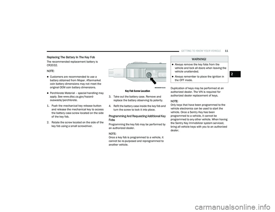
1. Push the mechanical key release button and release the mechanical key to access
the battery case screw located on the side
of the key fob.
2. Rotate the screw located on the side of the key fob using a small screwdriver.
Key Fob Screw Location
3. Take out the battery case. Remove and replace the battery observing its polarity.
4. Refit the battery case inside the key fob and turn the screw to lock it into place.
Programming And Requesting Additional Key
Fobs
Programming the key fob may be performed by
an authorized dealer.
NOTE:
Once a key fob is programmed to a vehicle, it
cannot be re-purposed and reprogrammed to
another vehicle. Duplication of keys may be performed at an
authorized dealer. The VIN is required for
authorized dealer replacement of keys.
NOTE:
Only keys that have been programmed to the
vehicle electronics can be used to start the
vehicle. Once a Sentry Key has been
programmed to a vehicle, it cannot be
programmed to any other vehicle. When having
the Sentry Key Immobilizer system serviced,
bring all vehicle keys with you to an authorized
dealer.
WARNING!
Always remove the key fobs from the
vehicle and lock all doors when leaving the
vehicle unattended.
Always remember to place the ignition in
the OFF mode.2
21_VM_OM_EN_USC_t.book Page 11
Page 15 of 280
GETTING TO KNOW YOUR VEHICLE13
NOTE:
When opening the driver’s door with the key in
the ignition and the ignition placed in the STOP
(OFF/LOCK) position, a chime will sound to
remind you to remove the key.
VEHICLE SECURITY SYSTEM — IF EQUIPPED
The Vehicle Security system monitors the
vehicle doors and ignition for unauthorized
operation. When the Vehicle Security system is
activated, interior switches for door locks are
disabled. The system provides both audible and
visible signals. Every intrusion attempt causes
six continuous alarm cycles. Every alarm cycle
lasts for 30 seconds. For 26 seconds, the horn
will sound, and the turn signal lights will flash.
For four seconds, it will pause. After a maximum
of 10 alarm cycles, only the turn signal lights will
flash until the next alarm activation.
To Arm The System
The Vehicle Security system will arm when you
use the key fob to lock the doors. If a door or the
hood is not properly shut, the alarm system will
not be armed.
To Disarm The System
Use the key fob to unlock the door and disarm
the system. The Vehicle Security system will also disarm if a
programmed Sentry Key is inserted into the
ignition switch. To exit the alarm mode, push
the key fob unlock button, or insert a
programmed Sentry Key into the ignition switch.
The Vehicle Security system is designed to
protect your vehicle. However, you can create
conditions where the system will give you a false
alarm. If one of the previously described arming
sequences has occurred, the Vehicle Security
system will arm regardless of whether you are in
the vehicle or not. If you remain in the vehicle
and open a door, the alarm will sound. If this
occurs, disarm the Vehicle Security system.
Rearming Of The System
If the system has not been disabled, the Vehicle
Security system will rearm itself after the
15 additional minutes of turn lamps flashing. If
the condition which initiated the alarm is still
present, the system will ignore that condition
and monitor the remaining doors and ignition.
Security System Manual Override
The Vehicle Security system will not arm if you
lock the doors using the manual door lock.
Do not leave the key fob in or near the
vehicle, or in a location accessible to chil-
dren. A child could operate power windows,
other controls, or move the vehicle.
Do not leave children or animals inside
parked vehicles in hot weather. Interior
heat build-up may cause serious injury or
death.
CAUTION!
An unlocked vehicle is an invitation. Always
remove the key from the ignition and lock all
the doors when leaving the vehicle
unattended.
WARNING!
(Continued)
2
21_VM_OM_EN_USC_t.book Page 13
Page 31 of 280
GETTING TO KNOW YOUR VEHICLE29
INTERIOR LIGHTS
Courtesy/Interior Lights
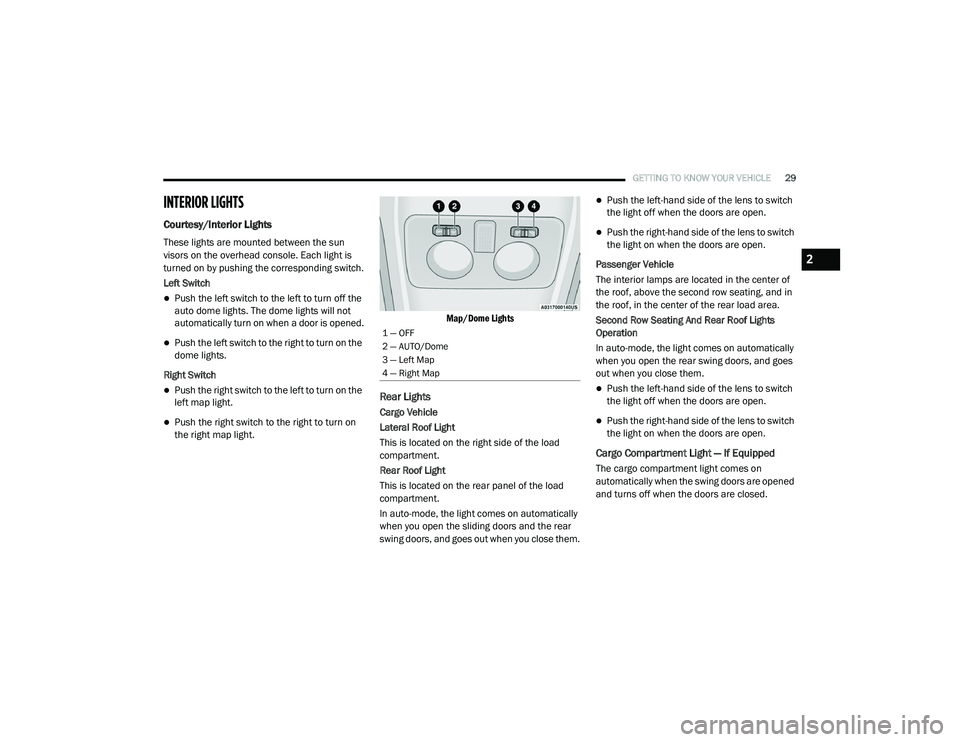
These lights are mounted between the sun
visors on the overhead console. Each light is
turned on by pushing the corresponding switch.
Left Switch
Push the left switch to the left to turn off the
auto dome lights. The dome lights will not
automatically turn on when a door is opened.
Push the left switch to the right to turn on the
dome lights.
Right Switch
Push the right switch to the left to turn on the
left map light.
Push the right switch to the right to turn on
the right map light.
Map/Dome Lights
Rear Lights
Cargo Vehicle
Lateral Roof Light
This is located on the right side of the load
compartment.
Rear Roof Light
This is located on the rear panel of the load
compartment.
In auto-mode, the light comes on automatically
when you open the sliding doors and the rear
swing doors, and goes out when you close them.
Push the left-hand side of the lens to switch
the light off when the doors are open.
Push the right-hand side of the lens to switch
the light on when the doors are open.
Passenger Vehicle
The interior lamps are located in the center of
the roof, above the second row seating, and in
the roof, in the center of the rear load area.
Second Row Seating And Rear Roof Lights
Operation
In auto-mode, the light comes on automatically
when you open the rear swing doors, and goes
out when you close them.
Push the left-hand side of the lens to switch
the light off when the doors are open.
Push the right-hand side of the lens to switch
the light on when the doors are open.
Cargo Compartment Light — If Equipped
The cargo compartment light comes on
automatically when the swing doors are opened
and turns off when the doors are closed.
1 — OFF
2 — AUTO/Dome
3 — Left Map
4 — Right Map
2
21_VM_OM_EN_USC_t.book Page 29
Page 32 of 280
30GETTING TO KNOW YOUR VEHICLE
WIPERS AND WASHERS
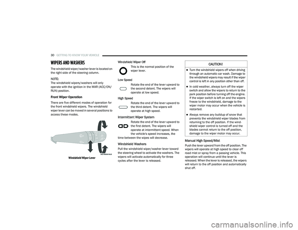
The windshield wiper/washer lever is located on
the right side of the steering column.
NOTE:
The windshield wipers/washers will only
operate with the ignition in the MAR (ACC/ON/
RUN) position.
Front Wiper Operation
There are five different modes of operation for
the front windshield wipers. The windshield
wiper lever can be moved in several positions to
access these modes.
Windshield Wiper Lever
Windshield Wiper Off
This is the normal position of the
wiper lever.
Low Speed Rotate the end of the lever upward to
the second detent. The wipers will
operate at low speed.
High Speed Rotate the end of the lever upward to
the third detent. The wipers will
operate at high speed.
Intermittent Wiper System
Rotate the end of the lever upward to
the first detent. The wipers will
operate at intermittent speed. When
the vehicle's speed increases, the
time between the wipes will decrease.
Windshield Washers
Pull the windshield wiper/washer lever toward
the steering wheel to activate the washers. The
wipers will activate automatically for three
cycles after the lever is released.
Manual High Speed/Mist
Push the lever upward from the off position. The
wipers will operate at high speed to clear off
road mist or spray from a passing vehicle. This
operation will continue until the lever is
released. When the lever is released, the wipers
will return to the off position and automatically
shut off.
CAUTION!
Turn the windshield wipers off when driving
through an automatic car wash. Damage to
the windshield wipers may result if the wiper
control is left in any position other than off.
In cold weather, always turn off the wiper
switch and allow the wipers to return to the
park position before turning off the engine.
If the wiper switch is left on and the wipers
freeze to the windshield, damage to the
wiper motor may occur when the vehicle is
restarted.
Always remove any buildup of snow that
prevents the windshield wiper blades from
returning to the off position. If the wind -
shield wiper control is turned off and the
blades cannot return to the off position,
damage to the wiper motor may occur.
21_VM_OM_EN_USC_t.book Page 30
Page 33 of 280

GETTING TO KNOW YOUR VEHICLE31
Rear Wiper Operation — If Equipped
Rear Windshield Wiper Operation
Rotate the windshield wiper lever center ring
upwards to operate the rear window wiper as
follows:
In intermittent mode when the front window
wiper is not operating
In synchronous mode (at half the speed of
the front window wiper) when the front
window wiper is operating
In continuous mode while vehicle is in
REVERSE
With the windshield wipers on, and REVERSE
gear engaged, rear window wiping will be
continuous in the same way.
Rear Windshield Washer Operation
Pushing the windshield wiper lever forward
activates the rear window washer. Keep the
windshield wiper lever pushed for more than
quarter of a second to activate the rear window
wiper as well. When the windshield wiper lever
is released, the wipers will return to normal
operation.
CLIMATE CONTROLS
The Climate Control system allows you to
regulate the temperature, air flow, and direction
of air circulating throughout the vehicle. The
controls are located on the instrument panel
below the radio.
Manual Climate Control Descriptions And
Functions
Manual Climate Controls
System Maintenance
In Winter, the Climate Control system must be
turned on at least once a month for about
10 minutes.
Have the system inspected at an authorized
dealer before the Summer.
A/C Button
Push the A/C button to engage the
Air Conditioning (A/C). A LED will
illuminate when the A/C system is
engaged. The A/C can be
deselected manually without
disturbing the mode control selection.
The Air Conditioning (A/C) button allows the
operator to manually activate or deactivate the
air conditioning system. When the air
conditioning system is turned on, cool
dehumidified air will flow through the outlets
into the cabin.
For Manual Climate Controls, if the system is
in Mix, Floor or Defrost Mode, the A/C can be
turned off, but the A/C system shall remain
active to prevent fogging of the windows.
If fog or mist appears on the windshield or
side glass, select Defrost mode, and increase
blower speed if needed.
If your air conditioning performance seems
lower than expected, check the front of the
A/C condenser (located in front of the radi -
ator), for an accumulation of dirt or insects.
Clean with a gentle water spray from the front
of the radiator and through the condenser.
2
21_VM_OM_EN_USC_t.book Page 31
Page 34 of 280
32GETTING TO KNOW YOUR VEHICLE
Recirculation Button
Press and release this button to
change the system between
recirculation mode and outside air
mode. The Recirculation indicator and
the A/C indicator illuminate when the
Recirculation button is pressed. Recirculation
can be used when outside conditions such as
smoke, odors, dust, or high humidity are
present. Recirculation can be used in all modes.
Recirculation may be unavailable (button on the
touchscreen greyed out) if conditions exist that
could create fogging on the inside of the
windshield. The A/C can be deselected
manually without disturbing the mode control
selection. Continuous use of the Recirculation
mode may make the inside air stuffy and
window fogging may occur. Extended use of this
mode is not recommended.
In cold weather, use of Recirculation mode may
lead to excessive window fogging. The
Recirculation feature may be unavailable if
conditions exist that could create fogging on the
inside of the windshield.
Front Defrost Button
Use Defrost mode with maximum
temperature settings for best
windshield and side window
defrosting and defogging. Turn the
knob to the Front Defrost position. Air comes
from the windshield and side window demist
outlets.
Rear Defrost Button — If Equipped
Push and release the Rear Defrost
Control button to turn on the rear
window defroster and the heated
outside mirrors (if equipped). An
indicator will illuminate when the rear window
defroster is on. The rear window defroster
automatically turns OFF after 20 minutes.
Temperature Control
Use this control to regulate the
temperature of the air inside the
passenger compartment. Rotating
the knob counterclockwise, from top
center into the blue area of the scale, indicates
cooler temperatures. Rotating the knob
clockwise, into the red area, indicates warmer
temperatures.
Blower Control
There are four blower speeds. Use
this control to regulate the amount of
air forced through the system in any
mode you select. The blower speed
increases as you move the control clockwise
from the OFF position.
Mode Control
Rotate this control to change the
airflow distribution mode. The airflow
distribution mode can be adjusted so
air comes from the instrument panel
outlets, floor outlets, defrost outlets and demist
outlets. The Mode settings are as follows:
Panel Mode
Air comes from the outlets in the
instrument panel. Each of these
outlets can be individually adjusted to
direct the flow of air. The air vanes of
the center outlets and outboard outlets can be
moved up and down or side to side to regulate
airflow direction. There is a shut off wheel
located below the air vanes to shut off or adjust
the amount of airflow from these outlets.
21_VM_OM_EN_USC_t.book Page 32