2021 RAM PROMASTER CITY horn
[x] Cancel search: hornPage 12 of 280

10
GETTING TO KNOW YOUR VEHICLE
KEYS
Key Fob
Your vehicle uses a key start ignition system
which supports Remote Keyless Entry (RKE).
The key fob allows you to lock or unlock the
doors from distances up to approximately 66 ft
(20 m). The key fob does not need to be pointed
at the vehicle to activate the system. The key
fob also contains an integrated mechanical key,
which can be accessed by pushing the
mechanical key release button.
NOTE:
The key fob may not be able to be detected by
the vehicle if it is located next to a mobile
phone, laptop or other electronic device; these
devices may block the key fob’s wireless signal.
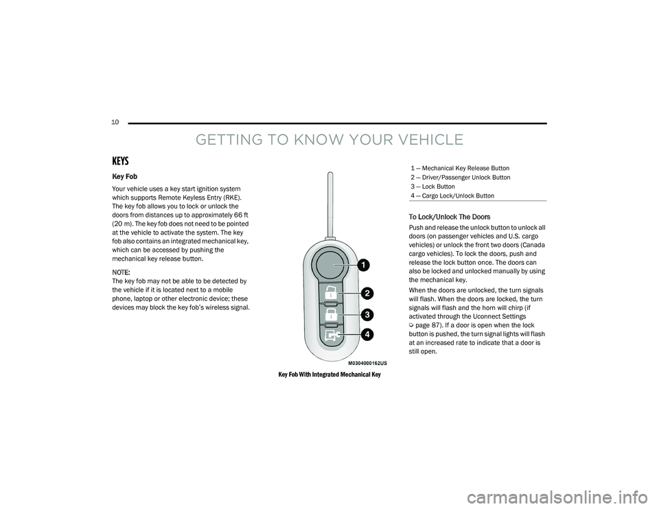
Key Fob With Integrated Mechanical Key
To Lock/Unlock The Doors
Push and release the unlock button to unlock all
doors (on passenger vehicles and U.S. cargo
vehicles) or unlock the front two doors (Canada
cargo vehicles). To lock the doors, push and
release the lock button once. The doors can
also be locked and unlocked manually by using
the mechanical key.
When the doors are unlocked, the turn signals
will flash. When the doors are locked, the turn
signals will flash and the horn will chirp (if
activated through the Uconnect Settings
Úpage 87). If a door is open when the lock
button is pushed, the turn signal lights will flash
at an increased rate to indicate that a door is
still open.
1 — Mechanical Key Release Button
2 — Driver/Passenger Unlock Button
3 — Lock Button
4 — Cargo Lock/Unlock Button
21_VM_OM_EN_USC_t.book Page 10
Page 15 of 280

GETTING TO KNOW YOUR VEHICLE13
NOTE:
When opening the driver’s door with the key in
the ignition and the ignition placed in the STOP
(OFF/LOCK) position, a chime will sound to
remind you to remove the key.
VEHICLE SECURITY SYSTEM — IF EQUIPPED
The Vehicle Security system monitors the
vehicle doors and ignition for unauthorized
operation. When the Vehicle Security system is
activated, interior switches for door locks are
disabled. The system provides both audible and
visible signals. Every intrusion attempt causes
six continuous alarm cycles. Every alarm cycle
lasts for 30 seconds. For 26 seconds, the horn
will sound, and the turn signal lights will flash.
For four seconds, it will pause. After a maximum
of 10 alarm cycles, only the turn signal lights will
flash until the next alarm activation.
To Arm The System
The Vehicle Security system will arm when you
use the key fob to lock the doors. If a door or the
hood is not properly shut, the alarm system will
not be armed.
To Disarm The System
Use the key fob to unlock the door and disarm
the system. The Vehicle Security system will also disarm if a
programmed Sentry Key is inserted into the
ignition switch. To exit the alarm mode, push
the key fob unlock button, or insert a
programmed Sentry Key into the ignition switch.
The Vehicle Security system is designed to
protect your vehicle. However, you can create
conditions where the system will give you a false
alarm. If one of the previously described arming
sequences has occurred, the Vehicle Security
system will arm regardless of whether you are in
the vehicle or not. If you remain in the vehicle
and open a door, the alarm will sound. If this
occurs, disarm the Vehicle Security system.
Rearming Of The System
If the system has not been disabled, the Vehicle
Security system will rearm itself after the
15 additional minutes of turn lamps flashing. If
the condition which initiated the alarm is still
present, the system will ignore that condition
and monitor the remaining doors and ignition.
Security System Manual Override
The Vehicle Security system will not arm if you
lock the doors using the manual door lock.
Do not leave the key fob in or near the
vehicle, or in a location accessible to chil-
dren. A child could operate power windows,
other controls, or move the vehicle.
Do not leave children or animals inside
parked vehicles in hot weather. Interior
heat build-up may cause serious injury or
death.
CAUTION!
An unlocked vehicle is an invitation. Always
remove the key from the ignition and lock all
the doors when leaving the vehicle
unattended.
WARNING!
(Continued)
2
21_VM_OM_EN_USC_t.book Page 13
Page 17 of 280

GETTING TO KNOW YOUR VEHICLE15
Closing/Locking With A Key Fob
Push and release the lock button on the key fob
to lock all doors, including the cargo area (side
lateral sliding doors and rear doors). The turn
signal lights will flash to acknowledge the lock
signal.
Horn activation settings after a key fob lock
command can be adjusted manually through
the Uconnect system Úpage 87.
Locking With The Mechanical Key In Passenger
Vehicle
Push the mechanical key release button to
expose the mechanical key, insert the key into
the driver door exterior lock cylinder and turn
the key clockwise to lock all doors.
Locking With The Mechanical Key In Cargo
Vehicle
Push the mechanical key release button to
expose the mechanical key, insert the key into
the driver door exterior lock cylinder and turn
the key clockwise to lock the front doors. Insert
the key into the rear door exterior lock cylinder
and turn the key clockwise to lock the rear
doors. Closing And Locking From Outside
Grab the side door handle and push towards
the front of the vehicle. Once the side door is
secured in the full closed position, use one of
the prior locking methods to lock the sliding
side doors.
Opening And Closing From The Inside
Opening:
Pull the interior door handle to unlock the door,
then pull the handle and slide the door towards
the rear of the vehicle until it can go no further.
Closing:
Pull the interior door handle to release the door
and then push it towards the front of the
vehicle.
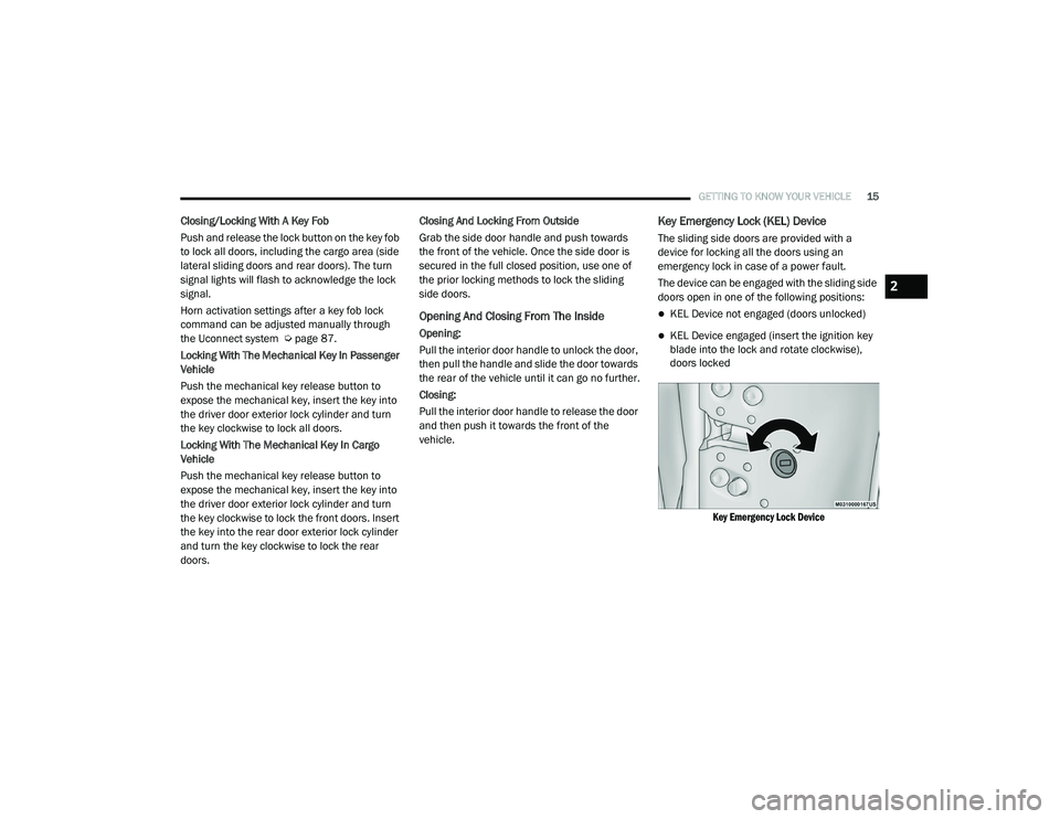
Key Emergency Lock (KEL) Device
The sliding side doors are provided with a
device for locking all the doors using an
emergency lock in case of a power fault.
The device can be engaged with the sliding side
doors open in one of the following positions:
KEL Device not engaged (doors unlocked)
KEL Device engaged (insert the ignition key
blade into the lock and rotate clockwise),
doors locked
Key Emergency Lock Device
2
21_VM_OM_EN_USC_t.book Page 15
Page 95 of 280

MULTIMEDIA93
Doors & Locks
When the Doors & Locks button is pressed on the touchscreen, the system displays the options related to locking and unlocking the vehicle’s doors.
Key Off Options
When the Key Off Option button is pressed on the touchscreen, the system displays the options related to vehicle shut off. These settings will only
activate when the ignition is set to OFF.
Setting Name Description
Sound Horn With Lock This setting will sound the horn when the key fob’s Lock button is pushed.
The “Off” setting will not sound the horn. The “1st Press” setting will
sound the horn when the Lock button is pushed once. The “2nd Press”
setting will sound the horn when the Lock button is pushed twice.
Auto Door Locks This setting will allow you to change if the doors lock automatically when
the vehicle reaches speeds of 12 mph (20 km/h).
Setting Name
Description
Radio Off Delay This setting will allow you to set the amount of time the radio remains on
after the vehicle has been turned off. The “0 min” setting will shut the
radio off the moment the vehicle is turned off. The “20 min” setting will
leave the radio on for 20 minutes after the vehicle has been turned off or
until one of the doors has been opened.
5
21_VM_OM_EN_USC_t.book Page 93
Page 170 of 280

168SAFETY
Enhanced Accident Response System
In the event of an impact, if the communication
network remains intact, and the power remains
intact, depending on the nature of the event,
the Occupant Restraint Controller (ORC) will
determine whether to have the Enhanced
Accident Response System perform the
following functions:
Cut off fuel to the engine (if equipped)
Cut off battery power to the electric motor (if
equipped)
Flash hazard lights as long as the battery has
power
Turn on the interior lights, which remain on
as long as the battery has power or for
15 minutes from the intervention of the
Enhanced Accident Response System
Unlock the power door locks
Your vehicle may also be designed to perform
any of these other functions in response to the
Enhanced Accident Response System:
Turn off the Fuel Filter Heater, Turn off the
HVAC Blower Motor, Close the HVAC Circula -
tion Door
Cut off battery power to the:
Engine
Electric Motor (if equipped)
Electric Power Steering
Brake booster
Electric park brake
Automatic transmission gear selector
Horn
Front wiper
Headlamp washer pump
NOTE:
After an accident, remember to cycle the igni -
tion to the STOP/OFF position and remove the
key from the ignition switch to avoid draining
the battery. Carefully check the vehicle for fuel
leaks in the engine compartment and on the
ground near the engine compartment and fuel
tank before resetting the system and starting
the engine. If there are no fuel leaks or damage
to the vehicle electrical devices (e.g. headlights)
after an accident, reset the system by following
the procedure described below. If you have any
doubt, contact an authorized dealer.
Enhanced Accident Response System Reset
Procedure
In order to reset the Enhanced Accident
Response System functions after an event, the
ignition switch must be changed from ignition
AVV/START or MAR/RUN to ignition STOP/OFF.
Carefully check the vehicle for fuel leaks in the
engine compartment and on the ground near
the engine compartment and fuel tank before
resetting the system and starting the engine.
After a crash, if the vehicle will not start after
performing the reset procedure, the vehicle
must be towed to an authorized dealer to be
inspected and to have the Enhanced Accident
Response System reset.
21_VM_OM_EN_USC_t.book Page 168
Page 192 of 280

190IN CASE OF EMERGENCY
CavityMaxi Fuse Mini Fuse Description
F0160 Amp Blue –Body Controller
F02 40 Amp Orange –Rear Power Windows, Fog Lamps, Front Heated Seats
(If Equipped)
F02 30 Amp Green –Rear Power Windows, Front Heated Seats (If Equipped)
F02 30 Amp Green –Fog Lamps, Front Heated Seats (If Equipped)
F02 20 Amp Yellow –Front Heated Seats (If Equipped)
F03 20 Amp Yellow –Ignition Switch
F04 40 Amp Orange –BSM System Module
F06 20 Amp Yellow –Radiator Fan - Low Speed
F07 50 Amp Red –Radiator Fan - High Speed
F08 40 Amp Orange –Blower Motor
F10 –15 Amp BlueHorn
F11 –10 Amp RedSecondary Loads ECM
F14 –15 Amp BlueHigh Beam
F15 –15 Amp BlueIP Power Outlet 12 Volt
F16 –5 Amp TanECM and Transmission Shifter
F17 –25 Amp ClearECM Power Loads
F18 –5 Amp TanECM Load, Main Relay
F19 –7.5 Amp Brown Air Conditioning
21_VM_OM_EN_USC_t.book Page 190