2021 RAM PROMASTER CITY ECO mode
[x] Cancel search: ECO modePage 110 of 280
108MULTIMEDIA
Seek Up/Seek Down
Seek Up /Seek Down
Press and release the Right Arrow button on
the touchscreen for the next selection. Press
and release the Left Arrow button on the
touchscreen to return to the beginning of the
current selection, or return to the beginning of
the previous selection if the track is within the
first few seconds of the current selection.
Fast Seek Up /Fast Seek Down
Press and hold the Right Arrow or Left Arrow
button on the touchscreen and the desired mode
will begin to fast forward or reverse through the
current track until the button on the touchscreen
is released.
Track Selection (Browse)
Rotate the Browse button to scroll through and
select a desired track on the device or USB.
Press the Exit button on the touchscreen if you
wish to cancel the browse function.
Repeat
Press the Repeat button on the touchscreen to
repeat the song selection. To cancel repeat,
press the Repeat button on the touchscreen a
second time. Shuffle
Press the Shuffle button on the touchscreen to
play the selections on the USB or Bluetooth®
device in random order to provide an interesting
change of pace. Press the Shuffle button on the
touchscreen a second time to turn this feature
off.
Info
Press the Info button to display the current
track information. Press the X button to cancel
this feature.
USB Mode
USB Mode is entered by either inserting a USB
Jump Drive cable into the USB port or by
pushing the Media button located on the
faceplate. Once in Media Mode, press the
Source button on the touchscreen and select
“USB”.
NOTE:
The system supports only FAT32 or ExFAT
formatted USB devices. The system does not
support devices with a capacity higher than
64GB. The system does not support USB hubs
connected to the USB port of the vehicle.
Connect your multimedia device directly to the
USB port using the specific connection cable for
the device if necessary.
Inserting USB Device
Gently insert the USB device into the USB Port.
If you insert a USB device with the ignition ON,
the unit will switch to USB Mode and begin to
play. The display will show the track number and
index time in minutes and seconds. Play will
begin at the start of track 1.
Browse
Press the Browse button on the touchscreen to
select Artist, Album, Genre, Song, Playlist or
Folder from the USB device. Once the desired
selection is made, you can chose from the
available media by pressing the button on the
touchscreen. Press the Exit button on the
touchscreen if you wish to cancel the browse
function.
Bluetooth® Mode
Before proceeding, the Bluetooth® device must
be paired with the Uconnect Phone to
communicate with the Uconnect system
Ú
page 112.
21_VM_OM_EN_USC_t.book Page 108
Page 123 of 280
MULTIMEDIA121
Siri® Eyes Free — If Equipped
When used with your Apple® iPhone®
connected to your vehicle, Siri lets you use your
voice to send text messages, select media,
place phone calls and much more. Siri uses
your natural language to understand what you
mean and responds back to confirm your
requests. The system is designed to keep your
eyes on the road and your hands on the wheel
by letting Siri help you perform useful tasks.
To enable Siri, push and hold, then release the
Uconnect Voice Recognition (VR) button on the
steering wheel. After you hear a double beep,
you can ask Siri to play podcasts and music, get
directions, read text messages, and many other
useful requests.
Bluetooth® Communication Link
Mobile phones may lose connection to the
Uconnect Phone. When this happens, the
connection can generally be re-established by
restarting the mobile phone. Your mobile phone
is recommended to remain in Bluetooth® ON
mode. Power-Up
After switching the ignition key from OFF to
either the ON/RUN or ACC position, or after a
language change, you must wait at least
15 seconds prior to using the system
Ú
page 265.
NAVIGATION MODE — IF EQUIPPED
Operating Navigation Mode — If Equipped
Planning A Route
Using the search bar provides a wide range of
ways to find places and then navigate to them.
You can search for your destination in different
ways:
A specific address
A partial address
A type of place
A zip code
A city to navigate to a city center
A Point of Interest (POI) near your current
location
Latitude and longitude coordinates Using Search
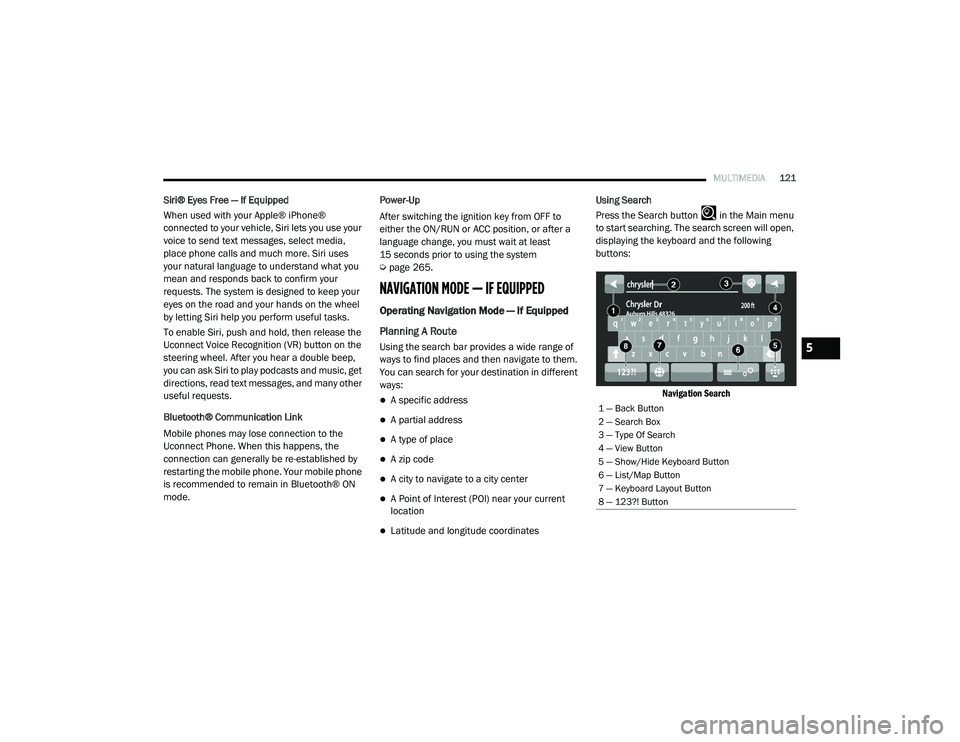
Press the Search button in the Main menu
to start searching. The search screen will open,
displaying the keyboard and the following
buttons:
Navigation Search
1 — Back Button
2 — Search Box
3 — Type Of Search
4 — View Button
5 — Show/Hide Keyboard Button
6 — List/Map Button
7 — Keyboard Layout Button
8 — 123?! Button
5
21_VM_OM_EN_USC_t.book Page 121
Page 144 of 280
142MULTIMEDIA
STEERING WHEEL AUDIO CONTROLS — IF
EQUIPPED
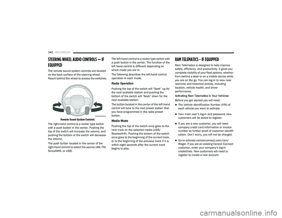
The remote sound system controls are located
on the back surface of the steering wheel.
Reach behind the wheel to access the switches.
Remote Sound System Controls
The right-hand control is a rocker type switch
with a push button in the center. Pushing the
top of the switch will increase the volume, and
pushing the bottom of the switch will decrease
the volume.
The push button located in the center of the
right-hand control to select the source (AM, FM,
SiriusXM®, or USB) The left-hand control is a rocker type switch with
a push button in the center. The function of the
left hand control is different depending on
which mode you are in.
The following describes the left-hand control
operation in each mode.
Radio Operation
Pushing the top of the switch will “Seek” up for
the next available station and pushing the
bottom of the switch will “Seek” down for the
next available station.
The button located in the center of the left-hand
control will tune to the next preset station that
you have programmed in the radio preset
button.
Media Mode
Pushing the top of the switch once goes to the
next track on the selected media (USB/
Bluetooth®). Pushing the bottom of the switch
once goes to the beginning of the current track,
or to the beginning of the previous track if it is
within eight seconds after the current track
begins to play.
RAM TELEMATICS - IF EQUIPPED
Ram Telematics is designed to help improve
safety, efficiency, and productivity. It gives you
complete visibility of your fleet options, whether
from behind a desk or on a mobile device while
you are on the go. You can log-in to view near
real-time and historical activity, including
location, vehicle health, and driver
performance.
Activating Ram Telematics In Your Vehicles
Before you get started you will need:
The Vehicle Identification Number (VIN) of
each vehicle you want to activate.
Your main user’s log-in and password; new
customers will be asked to register.
If you are a new customer, you will need
company credit card information or invoice
number as further proof of customer identifi
-
cation. Don’t worry, you will not be charged.
Go to activate.verizonconnect.com/ram/
#login. If you are an existing Verizon Connect
customer, enter your company’s log-in
credentials. New customers will need to
register to create a new account.
21_VM_OM_EN_USC_t.book Page 142
Page 150 of 280
148SAFETY
The ESC Activation/Malfunction Indicator Light
(located in the instrument cluster) starts to
flash as soon as the tires lose traction and the
ESC system becomes active. The ESC
Activation/Malfunction Indicator Light also
flashes when TCS is active. If the ESC
Activation/Malfunction Indicator Light begins to
flash during acceleration, ease up on the
accelerator and apply as little throttle as
possible. Be sure to adapt your speed and
driving to the prevailing road conditions.
The ESC OFF Indicator Light indicates
the Electronic Stability Control (ESC)
is in a reduced mode.
NOTE:
The ESC Activation/Malfunction Indicator
Light and the ESC OFF Indicator Light come
on momentarily each time the ignition switch
placed in the ON position.
Each time the ignition is placed in the ON
position, the ESC system will be on even if it
was turned off previously.
Electronic Roll Mitigation (ERM)
ERM anticipates the potential for wheel lift by
monitoring the driver’s steering wheel input and
the speed of the vehicle. When ERM determines
that the rate of change of the steering wheel
angle and vehicle’s speed are sufficient to
potentially cause wheel lift, it then applies the
appropriate brake and may also reduce engine
power to lessen the chance that wheel lift will
occur.
ERM can only reduce the chance of wheel lift
occurring during severe or evasive driving
maneuvers; it cannot prevent wheel lift due to
other factors, such as road conditions, leaving
the roadway, or striking objects or other
vehicles.
Hill Start Assist (HSA)
HSA is designed to assist the driver when
starting a vehicle from a stop on a hill. HSA will
maintain the level of brake pressure the driver
applied for a short period of time after the driver
takes their foot off of the brake pedal. If the
driver does not apply the throttle during this
short period of time, the system will release
brake pressure and the vehicle will roll down the
hill. The system will release brake pressure in
proportion to the amount of throttle applied as
the vehicle starts to move in the intended
direction of travel.
HSA Activation Criteria
The following criteria must be met in order for
HSA to activate:
The vehicle must be stopped.
The vehicle must be on a 5% (approximate)
grade or greater hill.
Gear selection matches vehicle uphill direc -
tion (i.e., vehicle facing uphill is in forward
gear; vehicle backing uphill is in REVERSE
gear).
WARNING!
Many factors, such as vehicle loading, road
conditions and driving conditions, influence
the chance that wheel lift or rollover may
occur. ERM cannot prevent all wheel lift or roll
overs, especially those that involve leaving
the roadway or striking objects or other vehi -
cles. The capabilities of an ERM-equipped
vehicle must never be exploited in a reckless
or dangerous manner which could jeopardize
the user's safety or the safety of others.
21_VM_OM_EN_USC_t.book Page 148
Page 151 of 280

SAFETY149
HSA will work in REVERSE and all forward gears
when the activation criteria have been met. The
system will not activate if the vehicle is placed
in NEUTRAL or PARK.
Traction Control System (TCS)
TCS monitors the amount of wheel spin of each
of the driven wheels. If wheel spin is detected,
brake pressure is applied to the slipping
wheel(s) and engine power is reduced to
provide enhanced acceleration and stability. A
feature of the TCS system, Brake Limited
Differential (BLD), functions similarly to a
limited slip differential and controls the wheel
spin across a driven axle. If one wheel on a
driven axle is spinning faster than the other, the
system will apply the brake of the spinning wheel. This will allow more engine torque to be
applied to the wheel that is not spinning. This
feature remains active even if TCS and ESC are
in the “Partial Off” mode Ú
page 146.
Trailer Sway Control (TSC) — If Equipped
TSC uses sensors in the vehicle to recognize an
excessively swaying trailer and will take the
appropriate actions to attempt to stop the sway.
The system may reduce engine power and apply
the brake of the appropriate wheel(s) to
counteract the sway of the trailer.
NOTE:
TSC cannot stop all trailers from swaying.
Always use caution when towing a trailer and
follow the trailer tongue weight recommenda -
tions Ú page 77.
When TSC is functioning, the ESC Activation/
Malfunction Indicator Light will flash, the engine
power may be reduced and you may feel the
brakes being applied to individual wheels to
attempt to stop the trailer from swaying. TSC is
disabled when the ESC system is in the “Partial
Off” mode.
AUXILIARY DRIVING SYSTEMS
Tire Pressure Monitoring System (TPMS)
The Tire Pressure Monitoring System (TPMS)
will warn the driver of a low tire pressure based
on the vehicle recommended cold placard
pressure.
The tire pressure will vary with temperature by
about 1 psi (7 kPa) for every 12°F (6.5°C). This
means that when the outside temperature
decreases, the tire pressure will decrease. Tire
pressure should always be set based on cold
inflation tire pressure. This is defined as the tire
pressure after the vehicle has not been driven
for at least three hours, or driven less than
1 mile (1.6 km) after a three hour period. The
cold tire inflation pressure must not exceed the
maximum inflation pressure molded into the
WARNING!
There may be situations on minor hills with a
loaded vehicle, or while pulling a trailer, when
the system will not activate and slight rolling
may occur. This could cause a collision with
another vehicle or object. Always remember
the driver is responsible for braking the
vehicle.
WARNING!
If TSC activates while driving, slow the vehicle
down, stop at the nearest safe location, and
adjust the trailer load to eliminate trailer
sway.
6
21_VM_OM_EN_USC_t.book Page 149
Page 163 of 280

SAFETY161
Supplemental Restraint Systems (SRS)
Some of the safety features described in this
section may be standard equipment on some
models, or may be optional equipment on
others. If you are not sure, ask an authorized
dealer.
The air bag system must be ready to protect you
in a collision. The Occupant Restraint Controller
(ORC) monitors the internal circuits and
interconnecting wiring associated with the
electrical Air Bag System Components. Your
vehicle may be equipped with the following Air
Bag System Components:
Air Bag System Components
Occupant Restraint Controller (ORC)
Air Bag Warning Light
Steering Wheel and Column
Instrument Panel
Knee Impact Bolsters
Driver and Front Passenger Air Bags
Seat Belt Buckle Switch
Supplemental Side Air Bags
Supplemental Knee Air Bags
Front and Side Impact Sensors
Seat Belt Pretensioners
Air Bag Warning Light
The Occupant Restraint Controller
(ORC) monitors the readiness of the
electronic parts of the air bag system
whenever the ignition switch is in the
AVV/START or MAR/ACC/ON/RUN position. If
the ignition switch is in the STOP/OFF/LOCK
position the air bag system is not on and the air
bags will not inflate. The ORC contains a backup power supply
system that may deploy the air bag system even
if the battery loses power or it becomes
disconnected prior to deployment.
The ORC turns on the Air Bag Warning Light in
the instrument panel for approximately four to
eight seconds for a self-check when the ignition
switch is in the MAR/ACC/ON/RUN position.
After the self-check, the Air Bag Warning Light
will turn off. If the ORC detects a malfunction in
any part of the system, it turns on the Air Bag
Warning Light, either momentarily or
continuously. A single chime will sound to alert
you if the light comes on again after initial
startup.
The ORC also includes diagnostics that will
illuminate the instrument panel Air Bag Warning
Light if a malfunction is detected that could
affect the air bag system. The diagnostics also
record the nature of the malfunction. While the
air bag system is designed to be maintenance
free, if any of the following occurs, have an
authorized dealer service the air bag system
immediately.
Failure to replace the seat belt assembly
could increase the risk of injury in colli
-
sions.
Do not use the Automatic Locking Mode to
restrain occupants who are wearing the
seat belt or children who are using booster
seats. The locked mode is only used to
install rear-facing or forward-facing child
restraints that have a harness for
restraining the child.
WARNING! (Continued)
6
21_VM_OM_EN_USC_t.book Page 161
Page 185 of 280
SAFETY183
The seat belt in the passenger seating position
is equipped with a Switchable Automatic
Locking Retractor (ALR). This seat belt is
designed to keep the lap portion of the seat belt
tight around the child restraint so that it is not
necessary to use a locking clip. The ALR
retractor can be “switched” into a locked mode
by pulling all of the webbing out of the retractor
and then letting the webbing retract back into
the retractor. If it is locked, the ALR will make a
clicking noise while the webbing is pulled back
into the retractor Ú page 159.
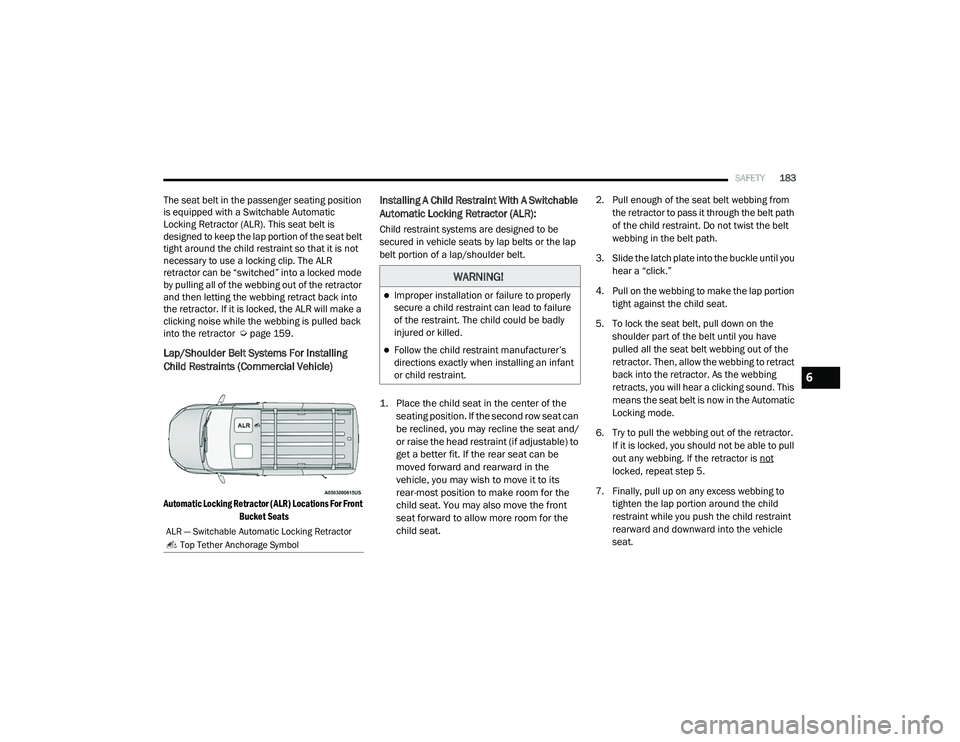
Lap/Shoulder Belt Systems For Installing
Child Restraints (Commercial Vehicle)
Automatic Locking Retractor (ALR) Locations For Front
Bucket Seats
Installing A Child Restraint With A Switchable
Automatic Locking Retractor (ALR):
Child restraint systems are designed to be
secured in vehicle seats by lap belts or the lap
belt portion of a lap/shoulder belt.
1. Place the child seat in the center of the seating position. If the second row seat can
be reclined, you may recline the seat and/
or raise the head restraint (if adjustable) to
get a better fit. If the rear seat can be
moved forward and rearward in the
vehicle, you may wish to move it to its
rear-most position to make room for the
child seat. You may also move the front
seat forward to allow more room for the
child seat.
2. Pull enough of the seat belt webbing from
the retractor to pass it through the belt path
of the child restraint. Do not twist the belt
webbing in the belt path.
3. Slide the latch plate into the buckle until you hear a “click.”
4. Pull on the webbing to make the lap portion tight against the child seat.
5. To lock the seat belt, pull down on the shoulder part of the belt until you have
pulled all the seat belt webbing out of the
retractor. Then, allow the webbing to retract
back into the retractor. As the webbing
retracts, you will hear a clicking sound. This
means the seat belt is now in the Automatic
Locking mode.
6. Try to pull the webbing out of the retractor. If it is locked, you should not be able to pull
out any webbing. If the retractor is not
locked, repeat step 5.
7. Finally, pull up on any excess webbing to tighten the lap portion around the child
restraint while you push the child restraint
rearward and downward into the vehicle
seat.
ALR — Switchable Automatic Locking Retractor
Top Tether Anchorage Symbol
WARNING!
Improper installation or failure to properly
secure a child restraint can lead to failure
of the restraint. The child could be badly
injured or killed.
Follow the child restraint manufacturer’s
directions exactly when installing an infant
or child restraint.
6
21_VM_OM_EN_USC_t.book Page 183
Page 188 of 280

186SAFETY
(Continued)
(Continued)
Air Bag Warning Light
The Air Bag Warning Light will turn on for four
to eight seconds as a bulb check when the
ignition switch is first placed in the on ON/RUN
position. If the light is either not on during
starting, stays on, or turns on while driving, have
the system inspected at an authorized dealer as
soon as possible. After the bulb check, this light
will illuminate with a single chime when a fault
with the Air Bag System has been detected. It
will stay on until the fault is removed. If the light
comes on intermittently or remains on while
driving, have an authorized dealer service the
vehicle immediately Ú
page 153.
Defroster
Check operation by selecting the defrost mode
and place the blower control on high speed. You
should be able to feel the air directed against
the windshield. See an authorized dealer for
service if your defroster is inoperable.
Floor Mat Safety Information
Always use floor mats designed to fit your
vehicle. Only use a floor mat that does not
interfere with the operation of the accelerator,
brake or clutch pedals. Only use a floor mat that
is securely attached using the floor mat fasteners so it cannot slip out of position and
interfere with the accelerator, brake or clutch
pedals or impair safe operation of your vehicle
in other ways.
WARNING!
An improperly attached, damaged, folded, or
stacked floor mat, or damaged floor mat
fasteners may cause your floor mat to
interfere with the accelerator, brake, or clutch
pedals and cause a loss of vehicle control. To
prevent SERIOUS INJURY or DEATH:
ALWAYS securely attach your floor mat
using the floor mat fasteners. DO NOT
install your floor mat upside down or turn
your floor mat over. Lightly pull to confirm
mat is secured using the floor mat
fasteners on a regular basis.
ALWAYS REMOVE THE EXISTING FLOOR
MAT FROM THE VEHICLE before
installing any other floor mat. NEVER install
or stack an additional floor mat on top of an
existing floor mat.
ONLY install floor mats designed to fit your
vehicle. NEVER install a floor mat that
cannot be properly attached and secured to
your vehicle. If a floor mat needs to be
replaced, only use a FCA approved floor
mat for the specific make, model, and year
of your vehicle.
ONLY use the driver’s side floor mat on the
driver’s side floor area. To check for inter
-
ference, with the vehicle properly parked
with the engine off, fully depress the accel -
erator, the brake, and the clutch pedal (if
present) to check for interference. If your
floor mat interferes with the operation of
any pedal, or is not secure to the floor,
remove the floor mat from the vehicle and
place the floor mat in your trunk.
ONLY use the passenger’s side floor mat on
the passenger’s side floor area.
ALWAYS make sure objects cannot fall or
slide into the driver’s side floor area when
the vehicle is moving. Objects can become
trapped under accelerator, brake, or clutch
pedals and could cause a loss of vehicle
control.
WARNING! (Continued)
21_VM_OM_EN_USC_t.book Page 186