2021 RAM PROMASTER CITY battery
[x] Cancel search: batteryPage 7 of 280

5
SERVICING AND MAINTENANCE
SCHEDULED SERVICING .................................. 217Maintenance Plan......................................217
ENGINE COMPARTMENT .................................. 221
Engine Compartment — 2.4L ...................221Checking Oil Level......................................222
Adding Washer Fluid .................................222
Maintenance-Free Battery .......................222
Pressure Washing ......................................223
DEALER SERVICE .............................................. 223
Engine Oil ...................................................223
Engine Oil Filter ..........................................224Engine Air Cleaner Filter ............................224
Air Conditioner Maintenance ....................225
Body Lubrication ........................................225
Windshield Wiper Blades ..........................225
Exhaust System ........................................226
Cooling System ..........................................227Brake System ............................................230
Automatic Transmission ...........................231
Upfitter Connectors — If Equipped ............232
TIRES ................................................................... 234
Tire Safety Information .............................. 234
Tires — General Information .....................242Tire Types ...................................................246
Spare Tires — If Equipped .........................247
Wheel And Wheel Trim Care .....................248Tire Chains and Traction Devices ............249
Tire Rotation Recommendations ..............250 DEPARTMENT OF TRANSPORTATION UNIFORM
TIRE QUALITY GRADES .....................................250
Treadwear .................................................. 250
Traction Grades ......................................... 251
Temperature Grades ................................. 251
STORING THE VEHICLE ......................................251
BODYWORK ........................................................ 252
Protection From Atmospheric Agents....... 252
Body And Underbody Maintenance .......... 252Preserving The Bodywork .......................... 252
INTERIORS ......................................................... 253
Seats And Fabric Parts .............................. 253
Plastic And Coated Parts ........................... 253
Leather Surfaces ....................................... 254Glass Surfaces .......................................... 254
TECHNICAL SPECIFICATIONS
VEHICLE IDENTIFICATION NUMBER.................255
BRAKE SYSTEM .................................................. 255
WHEEL AND TIRE TORQUE
SPECIFICATIONS ................................................ 255
Torque Specifications ................................ 255
FUEL REQUIREMENTS .......................................256
Gasoline Engine ......................................... 256
Reformulated Gasoline ............................. 256Gasoline/Oxygenate Blends .................... 257
E-85 Usage In Non-Flex Fuel Vehicles ...... 257
CNG And LP Fuel System Modifications... 257
MMT In Gasoline ........................................ 257
Materials Added To Fuel ........................... 257 Fuel System Cautions................................ 258
Carbon Monoxide Warnings ..................... 258
FLUID CAPACITIES ............................................. 259
ENGINE FLUIDS AND LUBRICANTS ................. 259
CHASSIS FLUIDS AND LUBRICANTS .............. 261
CUSTOMER ASSISTANCE
SUGGESTIONS FOR OBTAINING SERVICE FOR
YOUR VEHICLE .................................................. 262 Prepare For The Appointment .................. 262Prepare A List............................................. 262
Be Reasonable With Requests ................. 262
IF YOU NEED ASSISTANCE .............................. 262
FCA US LLC Customer Center ................... 262
FCA Canada Inc. Customer Center ........... 262
Mexico ........................................................ 263
Puerto Rico And US Virgin Islands ............ 263
Customer Assistance For The Hearing Or
Speech Impaired (TDD/TTY) ..................... 263 Service Contract ....................................... 263
WARRANTY INFORMATION .............................. 264
MOPAR PARTS................................................... 264
REPORTING SAFETY DEFECTS ........................ 264
In The 50 United States And
Washington, D.C. ....................................... 264 In Canada ................................................... 264
PUBLICATION ORDER FORMS ........................ 264
General Information.......................................... 265
21_VM_OM_EN_USC_t.book Page 5
Page 10 of 280
8
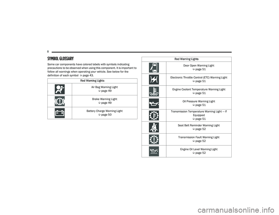
SYMBOL GLOSSARY
Some car components have colored labels with symbols indicating
precautions to be observed when using this component. It is important to
follow all warnings when operating your vehicle. See below for the
definition of each symbol Úpage 43.
Red Warning Lights
Air Bag Warning Light Úpage 49
Brake Warning Light Úpage 49
Battery Charge Warning Light Úpage 50
Red Warning Lights
Door Open Warning Light Úpage 51
Electronic Throttle Control (ETC) Warning Light Úpage 51
Engine Coolant Temperature Warning Light Úpage 51
Oil Pressure Warning Light Úpage 51
Transmission Temperature Warning Light — If Equipped
Ú page 51
Seat Belt Reminder Warning Light Úpage 52
Transmission Fault Warning Light Úpage 52
Engine Oil Level Warning Light Úpage 52
21_VM_OM_EN_USC_t.book Page 8
Page 13 of 280
GETTING TO KNOW YOUR VEHICLE11
Replacing The Battery In The Key Fob
The recommended replacement battery is
CR2032.
NOTE:
Customers are recommended to use a
battery obtained from Mopar. Aftermarket
coin battery dimensions may not meet the
original OEM coin battery dimensions.
Perchlorate Material – special handling may
apply. See www.dtsc.ca.gov/hazard-
ouswaste/perchlorate.
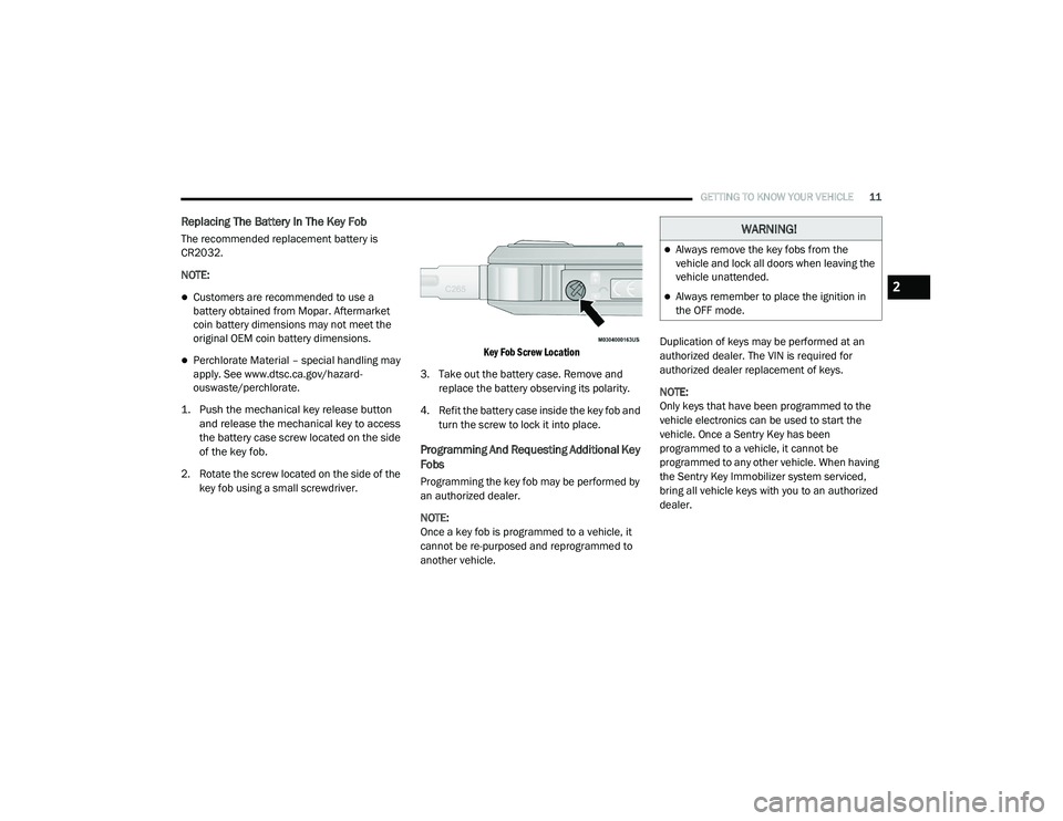
1. Push the mechanical key release button and release the mechanical key to access
the battery case screw located on the side
of the key fob.
2. Rotate the screw located on the side of the key fob using a small screwdriver.
Key Fob Screw Location
3. Take out the battery case. Remove and replace the battery observing its polarity.
4. Refit the battery case inside the key fob and turn the screw to lock it into place.
Programming And Requesting Additional Key
Fobs
Programming the key fob may be performed by
an authorized dealer.
NOTE:
Once a key fob is programmed to a vehicle, it
cannot be re-purposed and reprogrammed to
another vehicle. Duplication of keys may be performed at an
authorized dealer. The VIN is required for
authorized dealer replacement of keys.
NOTE:
Only keys that have been programmed to the
vehicle electronics can be used to start the
vehicle. Once a Sentry Key has been
programmed to a vehicle, it cannot be
programmed to any other vehicle. When having
the Sentry Key Immobilizer system serviced,
bring all vehicle keys with you to an authorized
dealer.
WARNING!
Always remove the key fobs from the
vehicle and lock all doors when leaving the
vehicle unattended.
Always remember to place the ignition in
the OFF mode.2
21_VM_OM_EN_USC_t.book Page 11
Page 38 of 280
36GETTING TO KNOW YOUR VEHICLE
If the window runs into any obstacle during
auto-closure, it will reverse direction and then
go back down. Remove the obstacle and use
the window switch again to close the window.
Power Windows System Initialization
The power windows may be reset if any of the
following occurs:
On the front doors:
Fuse or battery are disconnected when
the window is moving
50 window movements without ever
closing the window
On the rear doors (in addition to the condi -
tions for the front doors):
Fuse or battery are disconnected when
the window is moving
The auto-reverse system is activated
while the window is moving and the door
is opening
50 window movements without ever
closing the window
One door opening with the window
moving, without ever closing the door
Three door opening with the window in
motion. During these maneuvers, the
upper stop position is never reached
Proceed as follows for initialization:
1. Completely close the driver's door window, keeping the window switch pushed for at
least five seconds after the (upper) end of
travel position.
2. Proceed in the same way on the passenger's window switches.
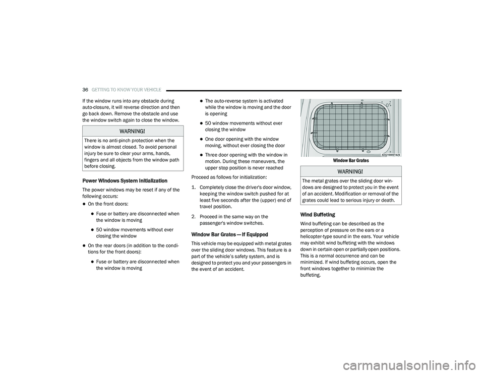
Window Bar Grates — If Equipped
This vehicle may be equipped with metal grates
over the sliding door windows. This feature is a
part of the vehicle’s safety system, and is
designed to protect you and your passengers in
the event of an accident.
Window Bar Grates
Wind Buffeting
Wind buffeting can be described as the
perception of pressure on the ears or a
helicopter-type sound in the ears. Your vehicle
may exhibit wind buffeting with the windows
down in certain open or partially open positions.
This is a normal occurrence and can be
minimized. If wind buffeting occurs, open the
front windows together to minimize the
buffeting.
WARNING!
There is no anti-pinch protection when the
window is almost closed. To avoid personal
injury be sure to clear your arms, hands,
fingers and all objects from the window path
before closing.
WARNING!
The metal grates over the sliding door win
-
dows are designed to protect you in the event
of an accident. Modification or removal of the
grates could lead to serious injury or death.
21_VM_OM_EN_USC_t.book Page 36
Page 42 of 280
40GETTING TO KNOW YOUR VEHICLE
USB Control — If Equipped
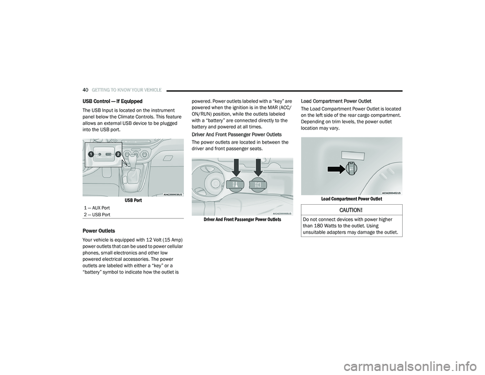
The USB Input is located on the instrument
panel below the Climate Controls. This feature
allows an external USB device to be plugged
into the USB port.
USB Port
Power Outlets
Your vehicle is equipped with 12 Volt (15 Amp)
power outlets that can be used to power cellular
phones, small electronics and other low
powered electrical accessories. The power
outlets are labeled with either a “key” or a
“battery” symbol to indicate how the outlet is powered. Power outlets labeled with a “key” are
powered when the ignition is in the MAR (ACC/
ON/RUN) position, while the outlets labeled
with a “battery” are connected directly to the
battery and powered at all times.
Driver And Front Passenger Power Outlets
The power outlets are located in between the
driver and front passenger seats.
Driver And Front Passenger Power Outlets
Load Compartment Power Outlet
The Load Compartment Power Outlet is located
on the left side of the rear cargo compartment.
Depending on trim levels, the power outlet
location may vary.
Load Compartment Power Outlet
1 — AUX Port
2 — USB Port CAUTION!
Do not connect devices with power higher
than 180 Watts to the outlet. Using
unsuitable adapters may damage the outlet.
21_VM_OM_EN_USC_t.book Page 40
Page 43 of 280
GETTING TO KNOW YOUR VEHICLE41
(Continued)
(Continued)
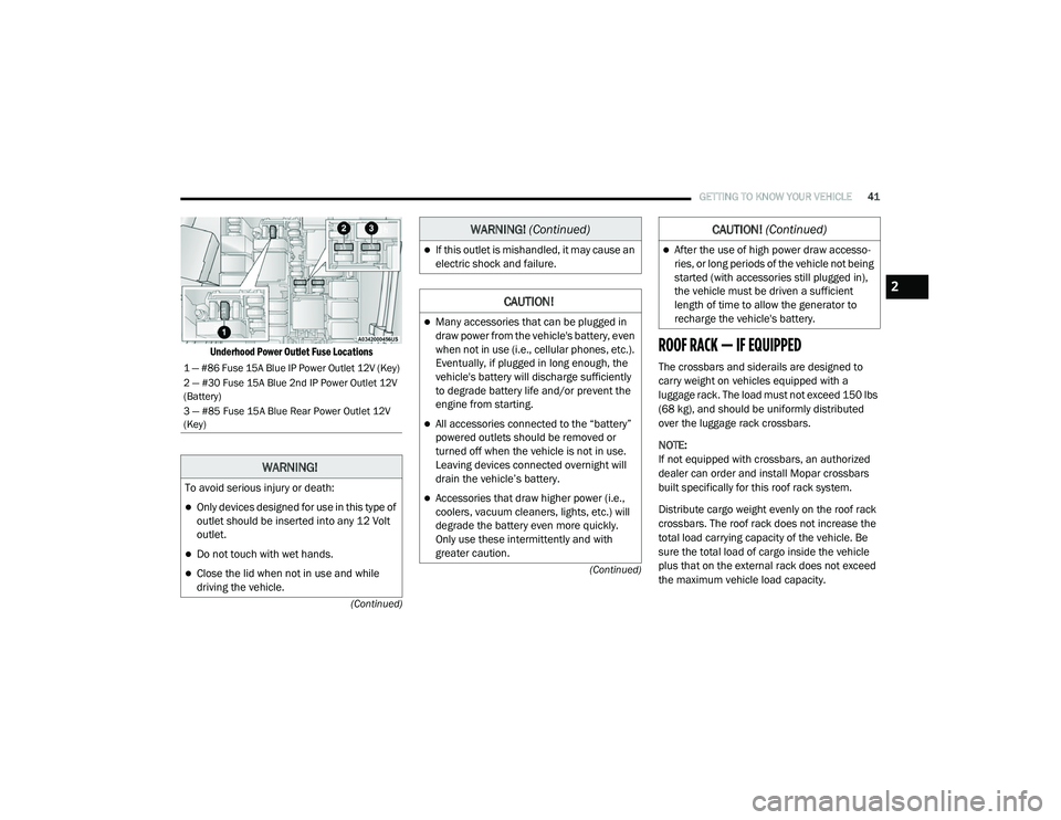
Underhood Power Outlet Fuse Locations
ROOF RACK — IF EQUIPPED
The crossbars and siderails are designed to
carry weight on vehicles equipped with a
luggage rack. The load must not exceed 150 lbs
(68 kg), and should be uniformly distributed
over the luggage rack crossbars.
NOTE:
If not equipped with crossbars, an authorized
dealer can order and install Mopar crossbars
built specifically for this roof rack system.
Distribute cargo weight evenly on the roof rack
crossbars. The roof rack does not increase the
total load carrying capacity of the vehicle. Be
sure the total load of cargo inside the vehicle
plus that on the external rack does not exceed
the maximum vehicle load capacity.1 — #86 Fuse 15A Blue IP Power Outlet 12V (Key)
2 — #30 Fuse 15A Blue 2nd IP Power Outlet 12V
(Battery)
3 — #85 Fuse 15A Blue Rear Power Outlet 12V
(Key)
WARNING!
To avoid serious injury or death:
Only devices designed for use in this type of
outlet should be inserted into any 12 Volt
outlet.
Do not touch with wet hands.
Close the lid when not in use and while
driving the vehicle.
If this outlet is mishandled, it may cause an
electric shock and failure.
CAUTION!
Many accessories that can be plugged in
draw power from the vehicle's battery, even
when not in use (i.e., cellular phones, etc.).
Eventually, if plugged in long enough, the
vehicle's battery will discharge sufficiently
to degrade battery life and/or prevent the
engine from starting.
All accessories connected to the “battery”
powered outlets should be removed or
turned off when the vehicle is not in use.
Leaving devices connected overnight will
drain the vehicle’s battery.
Accessories that draw higher power (i.e.,
coolers, vacuum cleaners, lights, etc.) will
degrade the battery even more quickly.
Only use these intermittently and with
greater caution.
WARNING! (Continued)
After the use of high power draw accesso -
ries, or long periods of the vehicle not being
started (with accessories still plugged in),
the vehicle must be driven a sufficient
length of time to allow the generator to
recharge the vehicle's battery.
CAUTION! (Continued)
2
21_VM_OM_EN_USC_t.book Page 41
Page 50 of 280
48GETTING TO KNOW YOUR INSTRUMENT PANEL
Trip Button
The TRIP button, located on the right steering
column stalk, can be used to display and to
reset the previously described values.
A short button push displays the different
values.
A long button push resets the system and
then starts a new trip.
New Trip
To reset:
Push and hold the TRIP button to reset the
system manually.
When the “Trip distance” reaches
99999.9 miles or kilometers or when the
“Travel time” reaches 999.59 (999 hours
and 59 minutes), the system is reset auto -
matically.
Disconnecting/Reconnecting the battery
resets the system. NOTE:
If the reset operation occurs in the presence of
the screens concerning Trip A or Trip B, only the
information associated with Trip A or Trip B
functions will be reset.
Start Of Trip Procedure
With the ignition on, push and hold the TRIP
button for over two seconds to reset trip
information.
Exit Trip
1. To exit the Trip function, wait until all the
values have been displayed or hold the
MENU
button for longer than one second.
2. Briefly push and release the MENU button
to go back to the menu screen or push and
hold the MENU button (approximately one
second) to go back to the main screen
without storing settings.
Trip Functions
Both trip functions are resettable (reset — start
of new trip).
“Trip A” can be used to display the figures
relating to:
Range
Trip distance A
Average Economy A
Instantaneous Economy
Average speed A
Travel time A (driving time)
“Trip B” can be used to display the figures
relating to:
Trip distance B
Average Economy B
Average speed B
Travel time B (driving time)
NOTE:
“Trip B” functions may be excluded (see “Trip B
Data”). Range and Instantaneous Economy
cannot be reset.
21_VM_OM_EN_USC_t.book Page 48
Page 52 of 280

50GETTING TO KNOW YOUR INSTRUMENT PANEL
If the light remains on when the parking brake
has been disengaged, and the fluid level is at
the full mark on the master cylinder reservoir, it
indicates a possible brake hydraulic system
malfunction or that a problem with the Brake
Booster has been detected by the Anti-Lock
Brake System (ABS) / Electronic Stability
Control (ESC) system. In this case, the light will
remain on until the condition has been
corrected. If the problem is related to the brake
booster, the ABS pump will run when applying
the brake, and a brake pedal pulsation may be
felt during each stop.
The dual brake system provides a reserve
braking capacity in the event of a failure to a
portion of the hydraulic system. A leak in either
half of the dual brake system is indicated by the
Brake Warning Light, which will turn on when
the brake fluid level in the master cylinder has
dropped below a specified level.
The light will remain on until the cause is
corrected. NOTE:
The light may flash momentarily during sharp
cornering maneuvers, which change fluid level
conditions. The vehicle should have service
performed, and the brake fluid level checked.
If brake failure is indicated, immediate repair is
necessary.
Vehicles equipped with the Anti-Lock Brake
System (ABS) are also equipped with Electronic
Brake Force Distribution (EBD). In the event of
an EBD failure, the Brake Warning Light will turn
on along with the ABS Light. Immediate repair to
the ABS system is required.
Operation of the Brake Warning Light can be
checked by turning the ignition switch from the
OFF position to the ON/RUN position. The light
should illuminate for approximately two seconds. The light should then turn off unless
the parking brake is applied or a brake fault is
detected. If the light does not illuminate, have
the light inspected by an authorized dealer.
The light also will turn on when the parking
brake is applied with the ignition switch in the
ON/RUN position.
NOTE:
This light shows only that the parking brake is
applied. It does not show the degree of brake
application.
Battery Charge Warning Light
This warning light will illuminate when
the battery is not charging properly. If
it stays on while the engine is running,
there may be a malfunction with the
charging system. Contact an authorized dealer
as soon as possible. This indicates a possible
problem with the electrical system or a related
component.
WARNING!
Driving a vehicle with the red brake light on is
dangerous. Part of the brake system may
have failed. It will take longer to stop the
vehicle. You could have a collision. Have the
vehicle checked immediately.
21_VM_OM_EN_USC_t.book Page 50