Page 145 of 280
 or upload a CSV file
with your VINs. A vehicle name is optional
and can be added later. Follow online instruc -
tions to complete your vehicle entry.
C")
MULTIMEDIA143
Manually enter the VIN(s) or upload a CSV file
with your VINs. A vehicle name is optional
and can be added later. Follow online instruc -
tions to complete your vehicle entry.
Create a password and enter billing informa -
tion. An email will be sent to you to complete
the final step. After that, you will be ready to
log-in and access Verizon Connect Fleet!
You are good to go! You will receive an email
confirming your vehicles are now online.
For more information, or to learn more, visit
www.verizonconnect.com/ram/.
Ram Telematics General Information
Modification Statement
Magneti Marelli has not approved any changes
or modifications to this device by the user. Any
changes or modifications could void the user’s
authority to operate the equipment.
Magneti Marelli n'approuve aucune
modification apportée à l'appareil par
l'utilisateur, quelle qu'en soit la nature. Tout
changement ou modification peuvent annuler
le droit d'utilisation de l'appareil par l'utilisateur. Interference Statement
This device complies with Part 15, 22, 24, and
27 of the FCC and Industry Canada
licence-exempt RSS standard(s). Operation is
subject to the following two conditions: (1) This
device may not cause interference, and (2) This
device must accept any interference, including
interference that may cause undesired
operation of the device.
Le présent appareil est conforme aux CNR
d'Industrie Canada applicables aux appareils
radio exempts de licence. L'exploitation est
autorisée aux deux conditions suivantes: (1)
l'appareil ne doit pas produire de brouillage, et
(2) l'utilisateur de l'appareil doit accepter tout
brouillage radioélectrique subi, même si le
broulliage est susceptible d'en compromettre le
fonctionnement.
RF Exposure
This equipment complies with FCC and IC
radiation exposure limits set forth for an
uncontrolled environment. The antenna should
be installed and operated with minimum
distance of 20 cm between the radiator and
your body.Cet appareil est conforme aux limites
d'exposition aux rayonnements de la IC pour
environnement non contrôlé. L'antenne doit
être installé de façon à garder une distance
minmale de 20 centimètres entre la source de
rayonnements et votre corps.
RADIO OPERATION AND MOBILE PHONES
Under certain conditions, the mobile phone
being on in your vehicle can cause erratic or
noisy performance from your radio. This
condition may be lessened or eliminated by
relocating the mobile phone. This condition is
not harmful to the radio. If your radio
performance does not satisfactorily “clear” by
the repositioning of the phone, it is
recommended that the radio volume be turned
down or off during mobile phone operation
when not using Uconnect (if equipped).
5
21_VM_OM_EN_USC_t.book Page 143
Page 146 of 280

144MULTIMEDIA
Regulatory And Safety Information
USA/CANADA
Exposure to Radio Frequency Radiation
The radiated output power of the internal
wireless radio is far below the FCC and IC radio
frequency exposure limits. Nevertheless, the
wireless radio will be used in such a manner
that the radio is 8 in (20 cm) or further from the
human body.
The internal wireless radio operates within
guidelines found in radio frequency safety
standards and recommendations, which reflect
the consensus of the scientific community. The radio manufacturer believes the internal
wireless radio is safe for use by consumers. The
level of energy emitted is far less than the
electromagnetic energy emitted by wireless
devices such as mobile phones. However, the
use of wireless radios may be restricted in some
situations or environments, such as aboard
airplanes. If you are unsure of restrictions, you
are encouraged to ask for authorization before
turning on the wireless radio Ú
page 265.
21_VM_OM_EN_USC_t.book Page 144
Page 147 of 280

SAFETY
SAFETY FEATURES
Four-Wheel Anti-Lock Brake System (ABS)
ABS is designed to aid the driver in maintaining
vehicle control under adverse braking
conditions. The system operat")
145
(Continued)
SAFETY
SAFETY FEATURES
Four-Wheel Anti-Lock Brake System (ABS)
ABS is designed to aid the driver in maintaining
vehicle control under adverse braking
conditions. The system operates with a
separate computer to modulate hydraulic
pressure, to prevent wheel lock-up and to help
avoid skidding on slippery surfaces.
The system's pump motor runs during an ABS
stop to provide regulated hydraulic pressure.
The pump motor makes a low humming noise
during operation, which is normal.
The ABS includes an amber ABS Warning Light.
When the light is illuminated, the ABS is not
functioning. The system reverts to standard
non-anti-lock brakes. Turning the ignition OFF
and ON again may reset the ABS if the fault
detected was only momentary.When you are in a severe braking condition
involving the use of the ABS, you will experience
some pedal drop as the vehicle comes to a stop.
This is the result of the system reverting to the
base brake system.
Engagement of the ABS may be accompanied
by a pulsing sensation. You may also hear a
clicking noise. These occurrences are normal
and indicate that the system is functioning
properly.
WARNING!
The ABS contains sophisticated electronic
equipment that may be susceptible to inter
-
ference caused by improperly installed or
high output radio transmitting equipment.
This interference can cause possible loss of
anti-lock braking capability. Installation of
such equipment should be performed by
qualified professionals.
Pumping of the Anti-Lock Brakes will
diminish their effectiveness and may lead
to a collision. Pumping makes the stopping
distance longer. Just press firmly on your
brake pedal when you need to slow down or
stop.
The ABS cannot prevent the natural laws of
physics from acting on the vehicle, nor can
it increase braking or steering efficiency
beyond that afforded by the condition of the
vehicle brakes and tires or the traction
afforded.
The ABS cannot prevent collisions,
including those resulting from excessive
speed in turns, following another vehicle
too closely, or hydroplaning.
The capabilities of an ABS equipped vehicle
must never be exploited in a reckless or
dangerous manner that could jeopardize
the user’s safety or the safety of others.
WARNING! (Continued)
6
21_VM_OM_EN_USC_t.book Page 145
Page 148 of 280
 System
Your vehicle is equipped with an advanced
Electronic Brake Control (EBC) system that
includes the Brake Assist System (BAS),
Traction Control Sys")
146SAFETY
Electronic Brake Control (EBC) System
Your vehicle is equipped with an advanced
Electronic Brake Control (EBC) system that
includes the Brake Assist System (BAS),
Traction Control System (TCS), Hill Start Assist
(HSA), Electronic Stability Control (ESC),
Electronic Roll Mitigation (ERM) and Trailer
Sway Control (TSC). All systems work together to
enhance vehicle stability and control in various
driving conditions and are commonly referred to
as ESC.
Brake Assist System (BAS)
BAS is designed to optimize the vehicle’s
braking capability during emergency braking
maneuvers. The system detects an emergency
braking situation by sensing the rate and
amount of brake application and then applies
optimum pressure to the brakes. This can help
reduce braking distances. The BAS
complements the Anti-Lock Brake System
(ABS). Applying the brakes very quickly results
in the best BAS assistance. To receive the
benefit of the system, you must apply continuous braking pressure during the
stopping sequence (do not “pump” the brakes).
Do not reduce brake pedal pressure unless
braking is no longer desired. Once the brake
pedal is released, the BAS is deactivated.
Electronic Stability Control (ESC)
ESC enhances directional control and stability
of the vehicle under various driving conditions.
ESC corrects for over/under steering of the
vehicle by applying the brake of the appropriate
wheel to counteract the above conditions.
Engine power may also be reduced to help the
vehicle maintain the desired path.
Oversteer - when the vehicle is turning more
than appropriate for the steering wheel posi
-
tion.
Understeer - when the vehicle is turning less
than appropriate for the steering wheel posi -
tion.
ESC uses sensors in the vehicle to determine
the vehicle path intended by the driver and
compares it to the actual path of the vehicle.
When the actual path does not match the
intended path, ESC applies the brake of the
appropriate wheel to assist in counteracting the
oversteer or understeer condition.
WARNING!
The Brake Assist System (BAS) cannot
prevent the natural laws of physics from
acting on the vehicle, nor can it increase the
traction afforded by prevailing road
conditions. BAS cannot prevent collisions,
including those resulting from excessive
speed in turns, driving on very slippery
surfaces, or hydroplaning. The capabilities of
a BAS-equipped vehicle must never be
exploited in a reckless or dangerous manner,
which could jeopardize the user's safety or
the safety of others.
21_VM_OM_EN_USC_t.book Page 146
Page 149 of 280

ESC Activation/Malfunction Indicator Light
And ESC OFF Indicator Light
The ESC Activation/Malfunction
Indicator Light in the instrument
cluster will come on when the ignitio")
SAFETY147
(Continued)
ESC Activation/Malfunction Indicator Light
And ESC OFF Indicator Light
The ESC Activation/Malfunction
Indicator Light in the instrument
cluster will come on when the ignition
switch is turned to the MAR (ON/RUN)
position for four seconds. If the ESC Activation/
Malfunction Indicator Light comes on
continuously with the engine running, a
malfunction has been detected in the ESC
system. If this light remains on after several
ignition cycles, and the vehicle has been driven
several miles (km) at speeds greater than
30 mph (48 km/h), see an authorized dealer as
soon as possible to have the problem
diagnosed and corrected.
WARNING!
Electronic Stability Control (ESC) cannot
prevent the natural laws of physics from
acting on the vehicle, nor can it increase
the traction afforded by prevailing road
conditions. ESC cannot prevent accidents,
including those resulting from excessive
speed in turns, driving on very slippery
surfaces, or hydroplaning. ESC also cannot
prevent accidents resulting from loss of
vehicle control due to inappropriate driver
input for the conditions. Only a safe, atten -
tive, and skillful driver can prevent acci -
dents. The capabilities of an ESC equipped
vehicle must never be exploited in a reck -
less or dangerous manner which could
jeopardize the user’s safety or the safety of
others.Vehicle modifications, or failure to properly
maintain your vehicle, may change the
handling characteristics of your vehicle,
and may negatively affect the performance
of the ESC system. Changes to the steering
system, suspension, braking system, tire
type and size or wheel size may adversely
affect ESC performance. Improperly
inflated and unevenly worn tires may also
degrade ESC performance. Any vehicle
modification or poor vehicle maintenance
that reduces the effectiveness of the ESC
system can increase the risk of loss of
vehicle control, vehicle rollover, personal
injury and death.
WARNING! (Continued)
6
21_VM_OM_EN_USC_t.book Page 147
Page 150 of 280
 starts to
flash as soon as the tires lose traction and the
ESC system becomes active. The ESC
Activa")
148SAFETY
The ESC Activation/Malfunction Indicator Light
(located in the instrument cluster) starts to
flash as soon as the tires lose traction and the
ESC system becomes active. The ESC
Activation/Malfunction Indicator Light also
flashes when TCS is active. If the ESC
Activation/Malfunction Indicator Light begins to
flash during acceleration, ease up on the
accelerator and apply as little throttle as
possible. Be sure to adapt your speed and
driving to the prevailing road conditions.
The ESC OFF Indicator Light indicates
the Electronic Stability Control (ESC)
is in a reduced mode.
NOTE:
The ESC Activation/Malfunction Indicator
Light and the ESC OFF Indicator Light come
on momentarily each time the ignition switch
placed in the ON position.
Each time the ignition is placed in the ON
position, the ESC system will be on even if it
was turned off previously.
Electronic Roll Mitigation (ERM)
ERM anticipates the potential for wheel lift by
monitoring the driver’s steering wheel input and
the speed of the vehicle. When ERM determines
that the rate of change of the steering wheel
angle and vehicle’s speed are sufficient to
potentially cause wheel lift, it then applies the
appropriate brake and may also reduce engine
power to lessen the chance that wheel lift will
occur.
ERM can only reduce the chance of wheel lift
occurring during severe or evasive driving
maneuvers; it cannot prevent wheel lift due to
other factors, such as road conditions, leaving
the roadway, or striking objects or other
vehicles.
Hill Start Assist (HSA)
HSA is designed to assist the driver when
starting a vehicle from a stop on a hill. HSA will
maintain the level of brake pressure the driver
applied for a short period of time after the driver
takes their foot off of the brake pedal. If the
driver does not apply the throttle during this
short period of time, the system will release
brake pressure and the vehicle will roll down the
hill. The system will release brake pressure in
proportion to the amount of throttle applied as
the vehicle starts to move in the intended
direction of travel.
HSA Activation Criteria
The following criteria must be met in order for
HSA to activate:
The vehicle must be stopped.
The vehicle must be on a 5% (approximate)
grade or greater hill.
Gear selection matches vehicle uphill direc -
tion (i.e., vehicle facing uphill is in forward
gear; vehicle backing uphill is in REVERSE
gear).
WARNING!
Many factors, such as vehicle loading, road
conditions and driving conditions, influence
the chance that wheel lift or rollover may
occur. ERM cannot prevent all wheel lift or roll
overs, especially those that involve leaving
the roadway or striking objects or other vehi -
cles. The capabilities of an ERM-equipped
vehicle must never be exploited in a reckless
or dangerous manner which could jeopardize
the user's safety or the safety of others.
21_VM_OM_EN_USC_t.book Page 148
Page 151 of 280

SAFETY149
HSA will work in REVERSE and all forward gears
when the activation criteria have been met. The
system will not activate if the vehicle is placed
in NEUTRAL or PARK.
Traction Control System (TCS)
TCS monitors the amount of wheel spin of each
of the driven wheels. If wheel spin is detected,
brake pressure is applied to the slipping
wheel(s) and engine power is reduced to
provide enhanced acceleration and stability. A
feature of the TCS system, Brake Limited
Differential (BLD), functions similarly to a
limited slip differential and controls the wheel
spin across a driven axle. If one wheel on a
driven axle is spinning faster than the other, the
system will apply the brake of the spinning wheel. This will allow more engine torque to be
applied to the wheel that is not spinning. This
feature remains active even if TCS and ESC are
in the “Partial Off” mode Ú
page 146.
Trailer Sway Control (TSC) — If Equipped
TSC uses sensors in the vehicle to recognize an
excessively swaying trailer and will take the
appropriate actions to attempt to stop the sway.
The system may reduce engine power and apply
the brake of the appropriate wheel(s) to
counteract the sway of the trailer.
NOTE:
TSC cannot stop all trailers from swaying.
Always use caution when towing a trailer and
follow the trailer tongue weight recommenda -
tions Ú page 77.
When TSC is functioning, the ESC Activation/
Malfunction Indicator Light will flash, the engine
power may be reduced and you may feel the
brakes being applied to individual wheels to
attempt to stop the trailer from swaying. TSC is
disabled when the ESC system is in the “Partial
Off” mode.
AUXILIARY DRIVING SYSTEMS
Tire Pressure Monitoring System (TPMS)
The Tire Pressure Monitoring System (TPMS)
will warn the driver of a low tire pressure based
on the vehicle recommended cold placard
pressure.
The tire pressure will vary with temperature by
about 1 psi (7 kPa) for every 12°F (6.5°C). This
means that when the outside temperature
decreases, the tire pressure will decrease. Tire
pressure should always be set based on cold
inflation tire pressure. This is defined as the tire
pressure after the vehicle has not been driven
for at least three hours, or driven less than
1 mile (1.6 km) after a three hour period. The
cold tire inflation pressure must not exceed the
maximum inflation pressure molded into the
WARNING!
There may be situations on minor hills with a
loaded vehicle, or while pulling a trailer, when
the system will not activate and slight rolling
may occur. This could cause a collision with
another vehicle or object. Always remember
the driver is responsible for braking the
vehicle.
WARNING!
If TSC activates while driving, slow the vehicle
down, stop at the nearest safe location, and
adjust the trailer load to eliminate trailer
sway.
6
21_VM_OM_EN_USC_t.book Page 149
Page 152 of 280

150SAFETY
tire sidewall. The tire pressure will also increase
as the vehicle is driven — this is normal and
there should be no adjustment for this
increased pressure.
See Úpage 234 on how to properly inflate the
vehicle’s tires.
The TPMS will warn the driver of a low tire
pressure if the tire pressure falls below the
low-pressure warning limit for any reason,
including low temperature effects and natural
pressure loss through the tire.
The TPMS will continue to warn the driver of low
tire pressure as long as the condition exists,
and will not turn off until the tire pressure is at
or above the recommended cold placard
pressure. Once the low tire pressure warning
(TPMS Warning Light) illuminates, you must
increase the tire pressure to the recommended
cold placard pressure in order for the TPMS
Warning Light to turn off. The system will
automatically update and the TPMS Warning
Light will turn off once the system receives the
updated tire pressures. The vehicle may need to
be driven for up to 20 minutes above 15 mph
(24 km/h) in order for the TPMS to receive this
information. NOTE:
When filling warm tires, the tire pressure may
need to be increased up to an additional 4 psi
(28 kPa) above the recommended cold placard
pressure in order to turn the TPMS Warning
Light off.
For example, your vehicle may have a
recommended cold (parked for more than three
hours) placard pressure of 30 psi (207 kPa). If
the ambient temperature is 68°F (20°C) and
the measured tire pressure is 27 psi (186 kPa),
a temperature drop to 20°F (-7°C) will
decrease the tire pressure to approximately
23 psi (158 kPa). This tire pressure is
sufficiently low enough to turn on the TPMS
Warning Light. Driving the vehicle may cause
the tire pressure to rise to approximately 27 psi
(186 kPa), but the TPMS Warning Light will still
be on. In this situation, the TPMS Warning Light
will turn off only after the tires are inflated to the
vehicle’s recommended cold placard pressure
value.CAUTION!
The TPMS has been optimized for the orig
-
inal equipment tires and wheels. TPMS
pressures and warning have been estab -
lished for the tire size equipped on your
vehicle. Undesirable system operation or
sensor damage may result when using
replacement equipment that is not of the
same size, type, and/or style. Aftermarket
wheels can cause sensor damage.
Using aftermarket tire sealants may cause
the Tire Pressure Monitoring System
(TPMS) sensor to become inoperable. After
using an aftermarket tire sealant it is
recommended that you take your vehicle to
an authorized dealership to have your
sensor function checked.
After inspecting or adjusting the tire pres -
sure always reinstall the valve stem cap.
This will prevent moisture and dirt from
entering the valve stem, which could
damage the TPMS sensor.
21_VM_OM_EN_USC_t.book Page 150
 1
1 2
2 3
3 4
4 5
5 6
6 7
7 8
8 9
9 10
10 11
11 12
12 13
13 14
14 15
15 16
16 17
17 18
18 19
19 20
20 21
21 22
22 23
23 24
24 25
25 26
26 27
27 28
28 29
29 30
30 31
31 32
32 33
33 34
34 35
35 36
36 37
37 38
38 39
39 40
40 41
41 42
42 43
43 44
44 45
45 46
46 47
47 48
48 49
49 50
50 51
51 52
52 53
53 54
54 55
55 56
56 57
57 58
58 59
59 60
60 61
61 62
62 63
63 64
64 65
65 66
66 67
67 68
68 69
69 70
70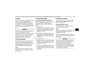 71
71 72
72 73
73 74
74 75
75 76
76 77
77 78
78 79
79 80
80 81
81 82
82 83
83 84
84 85
85 86
86 87
87 88
88 89
89 90
90 91
91 92
92 93
93 94
94 95
95 96
96 97
97 98
98 99
99 100
100 101
101 102
102 103
103 104
104 105
105 106
106 107
107 108
108 109
109 110
110 111
111 112
112 113
113 114
114 115
115 116
116 117
117 118
118 119
119 120
120 121
121 122
122 123
123 124
124 125
125 126
126 127
127 128
128 129
129 130
130 131
131 132
132 133
133 134
134 135
135 136
136 137
137 138
138 139
139 140
140 141
141 142
142 143
143 144
144 145
145 146
146 147
147 148
148 149
149 150
150 151
151 152
152 153
153 154
154 155
155 156
156 157
157 158
158 159
159 160
160 161
161 162
162 163
163 164
164 165
165 166
166 167
167 168
168 169
169 170
170 171
171 172
172 173
173 174
174 175
175 176
176 177
177 178
178 179
179 180
180 181
181 182
182 183
183 184
184 185
185 186
186 187
187 188
188 189
189 190
190 191
191 192
192 193
193 194
194 195
195 196
196 197
197 198
198 199
199 200
200 201
201 202
202 203
203 204
204 205
205 206
206 207
207 208
208 209
209 210
210 211
211 212
212 213
213 214
214 215
215 216
216 217
217 218
218 219
219 220
220 221
221 222
222 223
223 224
224 225
225 226
226 227
227 228
228 229
229 230
230 231
231 232
232 233
233 234
234 235
235 236
236 237
237 238
238 239
239 240
240 241
241 242
242 243
243 244
244 245
245 246
246 247
247 248
248 249
249 250
250 251
251 252
252 253
253 254
254 255
255 256
256 257
257 258
258 259
259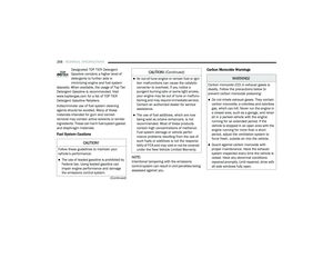 260
260 261
261 262
262 263
263 264
264 265
265 266
266 267
267 268
268 269
269 270
270 271
271 272
272 273
273 274
274 275
275 276
276 277
277 278
278 279
279