2021 RAM PROMASTER CITY steering wheel
[x] Cancel search: steering wheelPage 4 of 280

2
INTRODUCTION
Symbols Key ............................................................ 7
WARNINGS AND CAUTIONS ................................. 7
VAN CONVERSIONS/CAMPERS ............................ 7
VEHICLE MODIFICATIONS/ALTERATIONS .......... 8
Symbol Glossary ..................................................... 8
GETTING TO KNOW YOUR VEHICLE
KEYS ......................................................................10
Key Fob......................................................... 10
SENTRY KEY ..........................................................12
IGNITION SWITCH ................................................12
VEHICLE SECURITY SYSTEM — IF EQUIPPED ...13
To Arm The System ...................................... 13
To Disarm The System................................. 13
Rearming Of The System............................. 13
Security System Manual Override .............. 13
DOORS ..................................................................14
Power Door Locks ....................................... 14
Auto Unlock Doors ....................................... 14
Sliding Side Door ......................................... 14
Double Rear Swing Doors ........................... 16
Child-Protection Door Lock System ............ 17
SEATS ....................................................................17
Manual Adjustment (Front Seats)............... 18
Folding Rear Seat — If Equipped ................ 20
Heated Seats — If Equipped........................ 20 HEAD RESTRAINTS ............................................. 21
Front Adjustment ......................................... 21
Rear Adjustment — If Equipped .................. 22
Front Removal.............................................. 22
Rear Removal — If Equipped....................... 23
STEERING WHEEL ................................................ 23
Tilt/Telescoping Steering Column .............. 23
UCONNECT VOICE RECOGNITION QUICK
TIPS ........................................................................ 24
Introducing Voice Recognition .................... 24
Get Started ................................................... 24
Basic Voice Commands............................... 24
Additional Information ................................. 24
MIRRORS ............................................................. 25
Inside Rearview Mirror ................................ 25
Outside Mirrors ........................................... 25
Vanity Mirror................................................. 26
EXTERIOR LIGHTS ................................................ 27
Multifunction Lever...................................... 27
Headlights ................................................... 27
Daytime Running Lights (DRLs) —
If Equipped .................................................. 27 High/Low Beam Switch ............................... 28
Flash-To-Pass .............................................. 28
Parking Lights ............................................. 28
Follow Me Home/Headlight Delay .............. 28
Fog Lights — If Equipped ............................ 28
Turn Signals ................................................. 28
Lane Change Assist ..................................... 28
INTERIOR LIGHTS ................................................ 29
Courtesy/Interior Lights .............................. 29 WIPERS AND WASHERS .....................................30
Front Wiper Operation ................................. 30
Rear Wiper Operation — If Equipped .......... 31
CLIMATE CONTROLS ...........................................31
Manual Climate Control Descriptions And
Functions ..................................................... 31 Operating Tips.............................................. 33
WINDOWS ............................................................35
Power Window Controls — If Equipped ...... 35
Automatic Window Features ....................... 35
Power Windows System Initialization......... 36
Window Bar Grates — If Equipped .............. 36
Wind Buffeting ............................................ 36
HOOD .....................................................................37
Opening ........................................................ 37
Closing.......................................................... 37
CARGO AREA FEATURES .....................................38
Rear Cargo Tie-Downs ................................. 38
INTERIOR STORAGE AND EQUIPMENT ..............38
Storage ......................................................... 38
USB Control — If Equipped .......................... 40
Power Outlets .............................................. 40
ROOF RACK — IF EQUIPPED................................41
GETTING TO KNOW YOUR INSTRUMENT PANEL
INSTRUMENT CLUSTER........................................43
Instrument Cluster Descriptions................. 44
21_VM_OM_EN_USC_t.book Page 2
Page 6 of 280

4
MULTIMEDIA
UCONNECT SYSTEMS ..........................................86
CYBERSECURITY ..................................................86
UCONNECT SETTINGS .........................................87 Uconnect 3/3 NAV Settings ........................ 87
UCONNECT INTRODUCTION.................................97
Identifying Your Radio ................................. 97
Safety And General Information ................. 99
UCONNECT MODES ........................................... 100
Radio Mode ................................................100
Media Mode ...............................................107Phone Mode ..............................................109
NAVIGATION MODE — IF EQUIPPED ................ 121
Operating Navigation Mode —
If Equipped .................................................121
STEERING WHEEL AUDIO CONTROLS — IF
EQUIPPED ........................................................... 142
Radio Operation .........................................142
Media Mode ...............................................142
RAM TELEMATICS - IF EQUIPPED .................... 142
Ram Telematics General Information ......143
RADIO OPERATION AND MOBILE PHONES.... 143
Regulatory And Safety Information........... 144
SAFETY
SAFETY FEATURES ............................................ 145 Four-Wheel Anti-Lock Brake
System (ABS) ..............................................145 Electronic Brake Control (EBC) System ...146 AUXILIARY DRIVING SYSTEMS.........................149
Tire Pressure Monitoring
System (TPMS) ........................................... 149
OCCUPANT RESTRAINT SYSTEMS .................. 153
Occupant Restraint Systems .................... 153
Important Safety Precautions ................... 153
Seat Belt Systems ..................................... 154
Supplemental Restraint Systems (SRS)... 161
Child Restraints ......................................... 170
Transporting Pets ...................................... 184
SAFETY TIPS ....................................................... 185
Transporting Passengers .......................... 185Exhaust Gas .............................................. 185
Safety Checks You Should Make Inside
The Vehicle ................................................ 185 Periodic Safety Checks You Should Make
Outside The Vehicle ................................... 187
IN CASE OF EMERGENCY
HAZARD WARNING FLASHERS........................188
FUSES ..................................................................188
General Information .................................. 188Underhood Fuses ...................................... 189
Interior Fuses ............................................. 192
Central Unit Fuse Panel............................. 193 JACKING AND TIRE CHANGING ...................... 194
Jack Location — If Equipped ..................... 194
Removing The Spare Tire — If Equipped .. 194Preparations For Jacking ......................... 196
Jacking Instructions................................... 197
Vehicles With Alloy Wheels ....................... 200Vehicles Equipped With Wheel Covers .... 201
TIRE SERVICE KIT — IF EQUIPPED .................. 202
Tire Service Kit Storage............................. 202
Tire Service Kit Usage ............................... 202
JUMP STARTING ................................................ 204
Preparations For Jump Starting ................ 205
Jump Starting Procedure .......................... 206
IF YOUR ENGINE OVERHEATS ......................... 207
IGNITION KEY REMOVAL OVERRIDE ............... 208
GEAR SELECTOR OVERRIDE ............................ 209
FREEING A STUCK VEHICLE ............................ 209
TOWING A DISABLED VEHICLE ........................ 211
ENHANCED ACCIDENT RESPONSE SYSTEM
(EARS) ................................................................ 212
EVENT DATA RECORDER (EDR) ....................... 212
BULB REPLACEMENT ........................................ 213 Replacement Bulbs ................................... 213
Replacing Exterior Bulbs ........................... 214
Replacing Interior Bulbs ............................ 215
21_VM_OM_EN_USC_t.book Page 4
Page 25 of 280
GETTING TO KNOW YOUR VEHICLE23
Rear Removal — If Equipped
Outboard Head Restraints
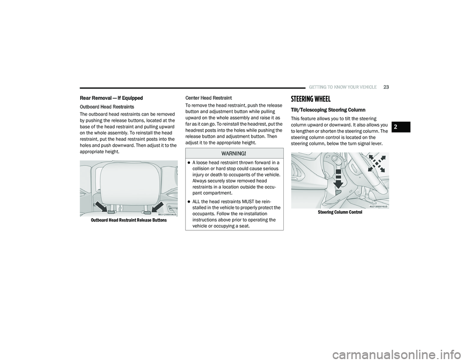
The outboard head restraints can be removed
by pushing the release buttons, located at the
base of the head restraint and pulling upward
on the whole assembly. To reinstall the head
restraint, put the head restraint posts into the
holes and push downward. Then adjust it to the
appropriate height.
Outboard Head Restraint Release Buttons
Center Head Restraint
To remove the head restraint, push the release
button and adjustment button while pulling
upward on the whole assembly and raise it as
far as it can go. To reinstall the headrest, put the
headrest posts into the holes while pushing the
release button and adjustment button. Then
adjust it to the appropriate height.
STEERING WHEEL
Tilt/Telescoping Steering Column
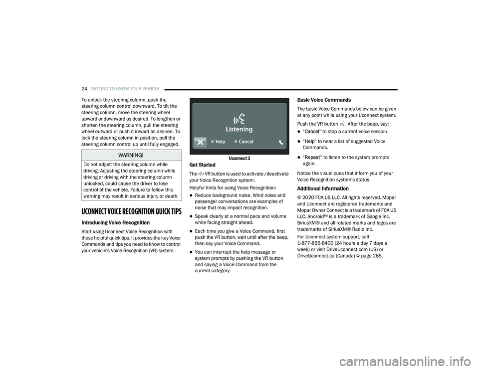
This feature allows you to tilt the steering
column upward or downward. It also allows you
to lengthen or shorten the steering column. The
steering column control is located on the
steering column, below the turn signal lever.
Steering Column Control
WARNING!
A loose head restraint thrown forward in a
collision or hard stop could cause serious
injury or death to occupants of the vehicle.
Always securely stow removed head
restraints in a location outside the occu -
pant compartment.
ALL the head restraints MUST be rein -
stalled in the vehicle to properly protect the
occupants. Follow the re-installation
instructions above prior to operating the
vehicle or occupying a seat.
2
21_VM_OM_EN_USC_t.book Page 23
Page 26 of 280
24GETTING TO KNOW YOUR VEHICLE
To unlock the steering column, push the
steering column control downward. To tilt the
steering column, move the steering wheel
upward or downward as desired. To lengthen or
shorten the steering column, pull the steering
wheel outward or push it inward as desired. To
lock the steering column in position, pull the
steering column control up until fully engaged.
UCONNECT VOICE RECOGNITION QUICK TIPS
Introducing Voice Recognition
Start using Uconnect Voice Recognition with
these helpful quick tips. It provides the key Voice
Commands and tips you need to know to control
your vehicle’s Voice Recognition (VR) system.
Uconnect 3
Get Started
The VR button is used to activate /deactivate
your Voice Recognition system.
Helpful hints for using Voice Recognition:
Reduce background noise. Wind noise and
passenger conversations are examples of
noise that may impact recognition.
Speak clearly at a normal pace and volume
while facing straight ahead.
Each time you give a Voice Command, first
push the VR button, wait until after the beep,
then say your Voice Command.
You can interrupt the help message or
system prompts by pushing the VR button
and saying a Voice Command from the
current category.
Basic Voice Commands
The basic Voice Commands below can be given
at any point while using your Uconnect system.
Push the VR button . After the beep, say:
“
Cancel ” to stop a current voice session.
“Help ” to hear a list of suggested Voice
Commands.
“ Repeat ” to listen to the system prompts
again.
Notice the visual cues that inform you of your
Voice Recognition system’s status.
Additional Information
© 2020 FCA US LLC. All rights reserved. Mopar
and Uconnect are registered trademarks and
Mopar Owner Connect is a trademark of FCA US
LLC. Android™ is a trademark of Google Inc.
SiriusXM® and all related marks and logos are
trademarks of SiriusXM® Radio Inc.
For Uconnect system support, call
1-877-855-8400 (24 hours a day 7 days a
week) or visit DriveUconnect.com (US) or DriveUconnect.ca (Canada) Ú page 265.
WARNING!
Do not adjust the steering column while
driving. Adjusting the steering column while
driving or driving with the steering column
unlocked, could cause the driver to lose
control of the vehicle. Failure to follow this
warning may result in serious injury or death.
21_VM_OM_EN_USC_t.book Page 24
Page 30 of 280

28GETTING TO KNOW YOUR VEHICLE
High/Low Beam Switch
Pull the multifunction lever toward the steering
wheel to switch the headlights to high beams.
Pull the multifunction lever again to turn the low
beams back on.
Flash-To-Pass
You can signal another vehicle with your
headlights by lightly pulling the multifunction
lever toward you. This will cause the high beam
headlights to turn on, and remain on, until the
lever is released.
Parking Lights
These lights can only be turned on with the
ignition in the STOP (OFF/LOCK) position or
removed. Move the end of the multifunction
lever to O (Off) position, and then to the
headlight position.
The indicator light telltale in the instrument
panel comes on. The lights stay on until the next
ignition cycle is performed.
Follow Me Home/Headlight Delay
When this feature is selected, the driver can
choose to have the headlights remain on for a
preset period of time after the engine is turned
off.
Activation
Remove the key or turn the ignition to the STOP
(OFF/LOCK) position, and pull the multifunction
lever toward the steering wheel within two
minutes. Each time the lever is pulled, the
activation of the lights will be extended by
30 seconds. The activation of the lights can be
extended to a maximum of 210 seconds.
Deactivation
Pull the multifunction lever toward the steering
wheel and hold it for more than two seconds.
Fog Lights — If Equipped
The fog light switch is located on the center
stack of the instrument panel, just above the
climate controls. Push the switch once to turn the fog
lights on. Push the switch a second
time to turn the fog lights off.
NOTE:
If the vehicle’s ignition is turned off, the fog
lights will also turn off.
Turn Signals
Move the multifunction lever up or down to
activate the turn signals. The arrows on each
side of the instrument cluster flash to show
proper operation.
NOTE:
If either light remains on and does not flash, or
there is a very fast flash rate, check for a defec -
tive outside light bulb.
Lane Change Assist
Lightly push the multifunction lever up or down,
without moving beyond the detent, and the turn
signal will flash five times then automatically
turn off.
21_VM_OM_EN_USC_t.book Page 28
Page 32 of 280
30GETTING TO KNOW YOUR VEHICLE
WIPERS AND WASHERS
The windshield wiper/washer lever is located on
the right side of the steering column.
NOTE:
The windshield wipers/washers will only
operate with the ignition in the MAR (ACC/ON/
RUN) position.
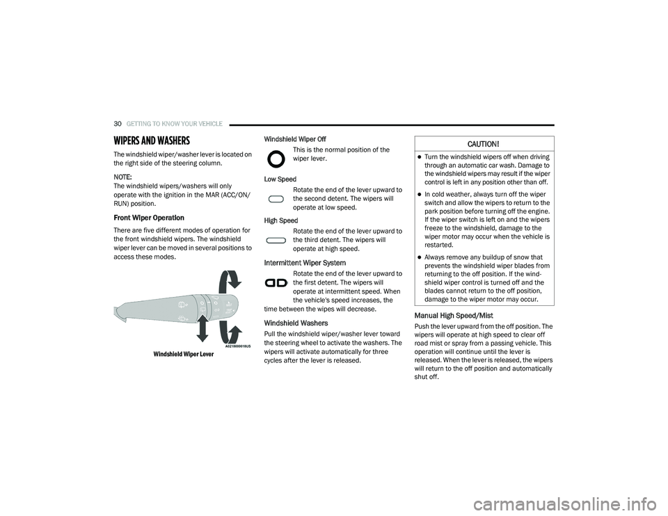
Front Wiper Operation
There are five different modes of operation for
the front windshield wipers. The windshield
wiper lever can be moved in several positions to
access these modes.
Windshield Wiper Lever
Windshield Wiper Off
This is the normal position of the
wiper lever.
Low Speed Rotate the end of the lever upward to
the second detent. The wipers will
operate at low speed.
High Speed Rotate the end of the lever upward to
the third detent. The wipers will
operate at high speed.
Intermittent Wiper System
Rotate the end of the lever upward to
the first detent. The wipers will
operate at intermittent speed. When
the vehicle's speed increases, the
time between the wipes will decrease.
Windshield Washers
Pull the windshield wiper/washer lever toward
the steering wheel to activate the washers. The
wipers will activate automatically for three
cycles after the lever is released.
Manual High Speed/Mist
Push the lever upward from the off position. The
wipers will operate at high speed to clear off
road mist or spray from a passing vehicle. This
operation will continue until the lever is
released. When the lever is released, the wipers
will return to the off position and automatically
shut off.
CAUTION!
Turn the windshield wipers off when driving
through an automatic car wash. Damage to
the windshield wipers may result if the wiper
control is left in any position other than off.
In cold weather, always turn off the wiper
switch and allow the wipers to return to the
park position before turning off the engine.
If the wiper switch is left on and the wipers
freeze to the windshield, damage to the
wiper motor may occur when the vehicle is
restarted.
Always remove any buildup of snow that
prevents the windshield wiper blades from
returning to the off position. If the wind -
shield wiper control is turned off and the
blades cannot return to the off position,
damage to the wiper motor may occur.
21_VM_OM_EN_USC_t.book Page 30
Page 46 of 280
44GETTING TO KNOW YOUR INSTRUMENT PANEL
Instrument Cluster Descriptions
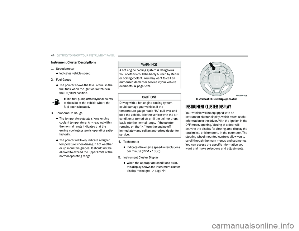
1. Speedometer
Indicates vehicle speed.
2. Fuel Gauge
The pointer shows the level of fuel in the
fuel tank when the ignition switch is in
the ON/RUN position.
The fuel pump arrow symbol points
to the side of the vehicle where the
fuel door is located.
3. Temperature Gauge
The temperature gauge shows engine
coolant temperature. Any reading within
the normal range indicates that the
engine cooling system is operating satis -
factorily.
The pointer will likely indicate a higher
temperature when driving in hot weather
or up mountain grades. It should not be
allowed to exceed the upper limits of the
normal operating range. 4. Tachometer
Indicates the engine speed in revolutions
per minute (RPM x 1000).
5. Instrument Cluster Display
When the appropriate conditions exist,
this display shows the instrument cluster
display messages Ú page 44.
Instrument Cluster Display Location
INSTRUMENT CLUSTER DISPLAY
Your vehicle will be equipped with an
instrument cluster display, which offers useful
information to the driver. With the ignition in the
OFF mode, opening/closing of a door will
activate the display for viewing, and display the
total miles, or kilometers, in the odometer. The
steering wheel mounted controls allow you to
scroll through the main menus and submenus.
You can access the specific information you
want and make selections and adjustments.
WARNING!
A hot engine cooling system is dangerous.
You or others could be badly burned by steam
or boiling coolant. You may want to call an
authorized dealer for service if your vehicle
overheats Ú
page 229.
CAUTION!
Driving with a hot engine cooling system
could damage your vehicle. If the
temperature gauge reads “H,” pull over and
stop the vehicle. Idle the vehicle with the air
conditioner turned off until the pointer drops
back into the normal range. If the pointer
remains on the “H,” turn the engine off
immediately and call an authorized dealer for
service.
21_VM_OM_EN_USC_t.book Page 44
Page 47 of 280
GETTING TO KNOW YOUR INSTRUMENT PANEL45
Location And Controls
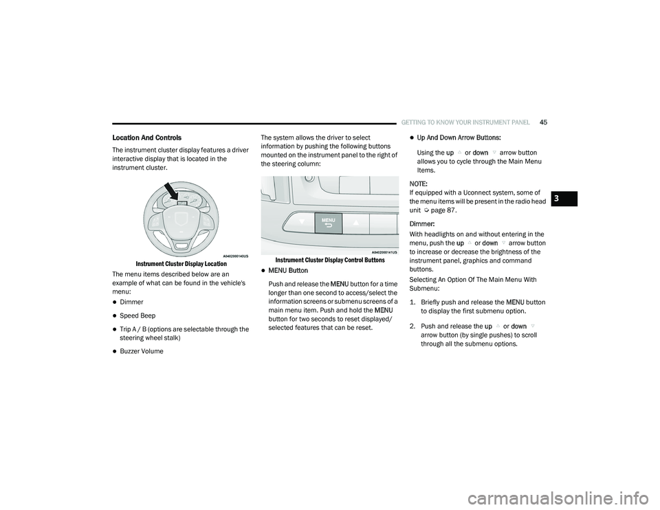
The instrument cluster display features a driver
interactive display that is located in the
instrument cluster.
Instrument Cluster Display Location
The menu items described below are an
example of what can be found in the vehicle's
menu:
Dimmer
Speed Beep
Trip A / B (options are selectable through the
steering wheel stalk)
Buzzer Volume The system allows the driver to select
information by pushing the following buttons
mounted on the instrument panel to the right of
the steering column:
Instrument Cluster Display Control Buttons
MENU Button
Push and release the MENU button for a time
longer than one second to access/select the
information screens or submenu screens of a
main menu item. Push and hold the MENU
button for two seconds to reset displayed/
selected features that can be reset.
Up And Down Arrow Buttons:
Using the up or down arrow button
allows you to cycle through the Main Menu
Items.
NOTE:
If equipped with a Uconnect system, some of
the menu items will be present in the radio head
unit Ú page 87.
Dimmer:
With headlights on and without entering in the
menu, push the up or down arrow button
to increase or decrease the brightness of the
instrument panel, graphics and command
buttons.
Selecting An Option Of The Main Menu With
Submenu:
1. Briefly push and release the
MENU
button
to display the first submenu option.
2. Push and release the up or down
arrow button (by single pushes) to scroll
through all the submenu options.
3
21_VM_OM_EN_USC_t.book Page 45