2021 RAM PROMASTER CITY length
[x] Cancel search: lengthPage 25 of 280
GETTING TO KNOW YOUR VEHICLE23
Rear Removal — If Equipped
Outboard Head Restraints
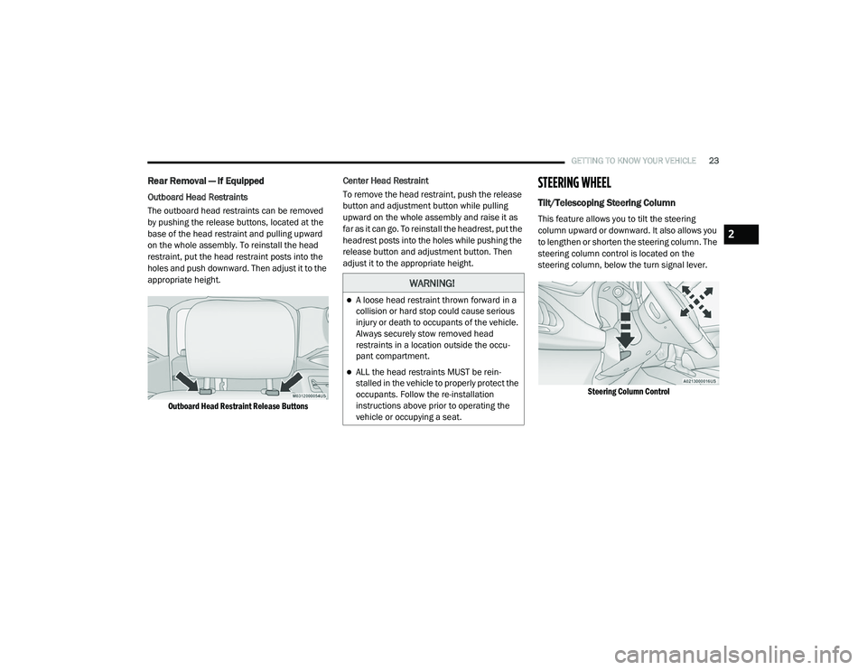
The outboard head restraints can be removed
by pushing the release buttons, located at the
base of the head restraint and pulling upward
on the whole assembly. To reinstall the head
restraint, put the head restraint posts into the
holes and push downward. Then adjust it to the
appropriate height.
Outboard Head Restraint Release Buttons
Center Head Restraint
To remove the head restraint, push the release
button and adjustment button while pulling
upward on the whole assembly and raise it as
far as it can go. To reinstall the headrest, put the
headrest posts into the holes while pushing the
release button and adjustment button. Then
adjust it to the appropriate height.
STEERING WHEEL
Tilt/Telescoping Steering Column
This feature allows you to tilt the steering
column upward or downward. It also allows you
to lengthen or shorten the steering column. The
steering column control is located on the
steering column, below the turn signal lever.
Steering Column Control
WARNING!
A loose head restraint thrown forward in a
collision or hard stop could cause serious
injury or death to occupants of the vehicle.
Always securely stow removed head
restraints in a location outside the occu -
pant compartment.
ALL the head restraints MUST be rein -
stalled in the vehicle to properly protect the
occupants. Follow the re-installation
instructions above prior to operating the
vehicle or occupying a seat.
2
21_VM_OM_EN_USC_t.book Page 23
Page 26 of 280
24GETTING TO KNOW YOUR VEHICLE
To unlock the steering column, push the
steering column control downward. To tilt the
steering column, move the steering wheel
upward or downward as desired. To lengthen or
shorten the steering column, pull the steering
wheel outward or push it inward as desired. To
lock the steering column in position, pull the
steering column control up until fully engaged.
UCONNECT VOICE RECOGNITION QUICK TIPS
Introducing Voice Recognition
Start using Uconnect Voice Recognition with
these helpful quick tips. It provides the key Voice
Commands and tips you need to know to control
your vehicle’s Voice Recognition (VR) system.
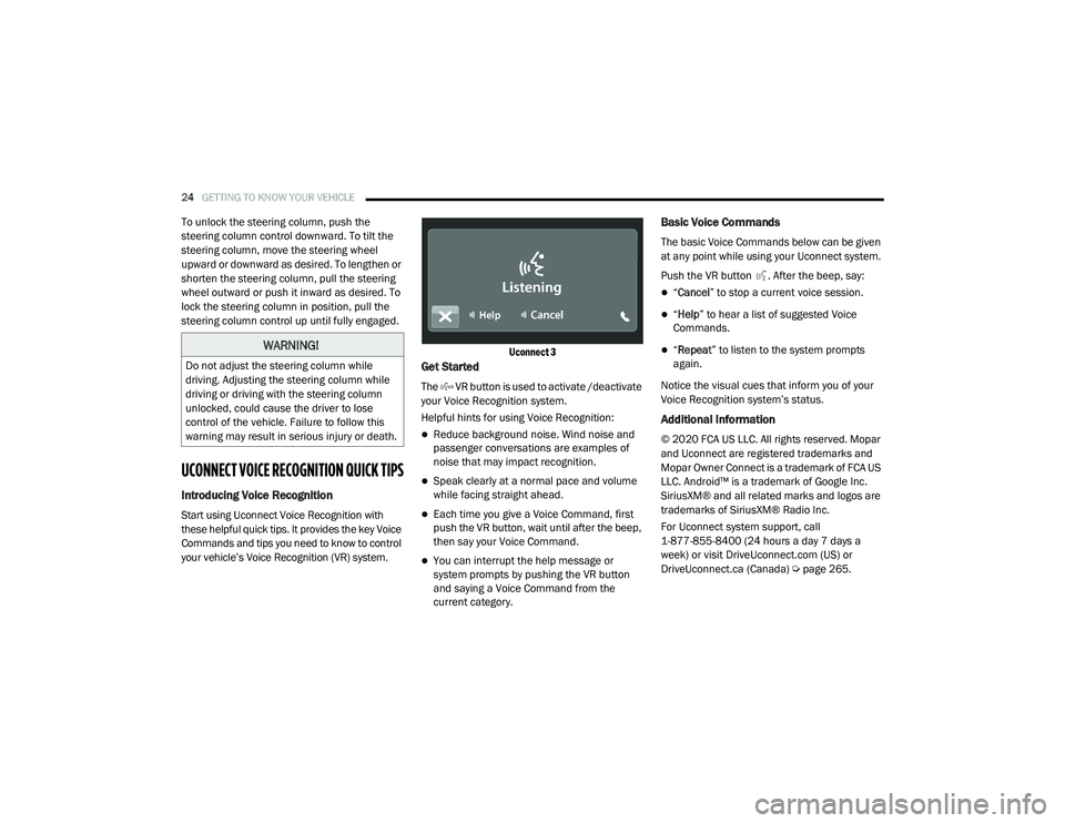
Uconnect 3
Get Started
The VR button is used to activate /deactivate
your Voice Recognition system.
Helpful hints for using Voice Recognition:
Reduce background noise. Wind noise and
passenger conversations are examples of
noise that may impact recognition.
Speak clearly at a normal pace and volume
while facing straight ahead.
Each time you give a Voice Command, first
push the VR button, wait until after the beep,
then say your Voice Command.
You can interrupt the help message or
system prompts by pushing the VR button
and saying a Voice Command from the
current category.
Basic Voice Commands
The basic Voice Commands below can be given
at any point while using your Uconnect system.
Push the VR button . After the beep, say:
“
Cancel ” to stop a current voice session.
“Help ” to hear a list of suggested Voice
Commands.
“ Repeat ” to listen to the system prompts
again.
Notice the visual cues that inform you of your
Voice Recognition system’s status.
Additional Information
© 2020 FCA US LLC. All rights reserved. Mopar
and Uconnect are registered trademarks and
Mopar Owner Connect is a trademark of FCA US
LLC. Android™ is a trademark of Google Inc.
SiriusXM® and all related marks and logos are
trademarks of SiriusXM® Radio Inc.
For Uconnect system support, call
1-877-855-8400 (24 hours a day 7 days a
week) or visit DriveUconnect.com (US) or DriveUconnect.ca (Canada) Ú page 265.
WARNING!
Do not adjust the steering column while
driving. Adjusting the steering column while
driving or driving with the steering column
unlocked, could cause the driver to lose
control of the vehicle. Failure to follow this
warning may result in serious injury or death.
21_VM_OM_EN_USC_t.book Page 24
Page 43 of 280
GETTING TO KNOW YOUR VEHICLE41
(Continued)
(Continued)
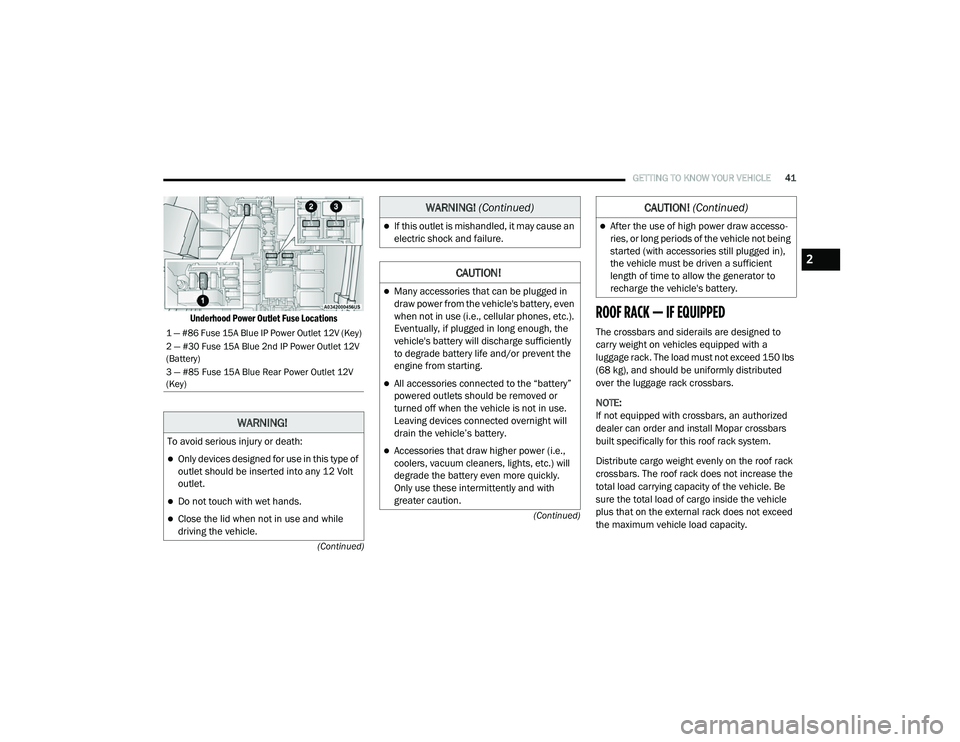
Underhood Power Outlet Fuse Locations
ROOF RACK — IF EQUIPPED
The crossbars and siderails are designed to
carry weight on vehicles equipped with a
luggage rack. The load must not exceed 150 lbs
(68 kg), and should be uniformly distributed
over the luggage rack crossbars.
NOTE:
If not equipped with crossbars, an authorized
dealer can order and install Mopar crossbars
built specifically for this roof rack system.
Distribute cargo weight evenly on the roof rack
crossbars. The roof rack does not increase the
total load carrying capacity of the vehicle. Be
sure the total load of cargo inside the vehicle
plus that on the external rack does not exceed
the maximum vehicle load capacity.1 — #86 Fuse 15A Blue IP Power Outlet 12V (Key)
2 — #30 Fuse 15A Blue 2nd IP Power Outlet 12V
(Battery)
3 — #85 Fuse 15A Blue Rear Power Outlet 12V
(Key)
WARNING!
To avoid serious injury or death:
Only devices designed for use in this type of
outlet should be inserted into any 12 Volt
outlet.
Do not touch with wet hands.
Close the lid when not in use and while
driving the vehicle.
If this outlet is mishandled, it may cause an
electric shock and failure.
CAUTION!
Many accessories that can be plugged in
draw power from the vehicle's battery, even
when not in use (i.e., cellular phones, etc.).
Eventually, if plugged in long enough, the
vehicle's battery will discharge sufficiently
to degrade battery life and/or prevent the
engine from starting.
All accessories connected to the “battery”
powered outlets should be removed or
turned off when the vehicle is not in use.
Leaving devices connected overnight will
drain the vehicle’s battery.
Accessories that draw higher power (i.e.,
coolers, vacuum cleaners, lights, etc.) will
degrade the battery even more quickly.
Only use these intermittently and with
greater caution.
WARNING! (Continued)
After the use of high power draw accesso -
ries, or long periods of the vehicle not being
started (with accessories still plugged in),
the vehicle must be driven a sufficient
length of time to allow the generator to
recharge the vehicle's battery.
CAUTION! (Continued)
2
21_VM_OM_EN_USC_t.book Page 41
Page 92 of 280
90MULTIMEDIA
Voice
When the Voice button is pressed on the touchscreen, the system displays the options related to the vehicle’s Voice Recognition feature.
Units
When the Units button is pressed on the touchscreen, the system displays the different measurement options. The selected unit of measurement will
display in the instrument cluster display and navigation system (if equipped). The available settings are:
Setting Name Description
Voice Response Length This setting will change the response length for the Voice Recognition
system. When set to “Brief”, the system provides a shortened audio
description. When set to “Detailed”, the system provides the full audio
description from the system.
Show Command List This setting will allow you to turn the Command List on or off. The
“Always” setting will always show the command list. The “With Help”
setting will show the command list and provide a brief description of what
the command does. The “Never” setting will turn the command list off.
Setting Name
Description
US This setting will change the unit of measurement on the display to US.
Metric This setting will change the unit of measurement on the display to Metric.
Custom The setting changes the “Speed” (MPH or km/h), “Distance” (mi or km),
“Fuel Consumption” (MPG [US], MPG [UK], L/100 km, or km/L),
“Pressure” (psi, kPa, or bar), “Temperature” (°C or °F) units of
measurement independently.
21_VM_OM_EN_USC_t.book Page 90
Page 134 of 280
132MULTIMEDIA
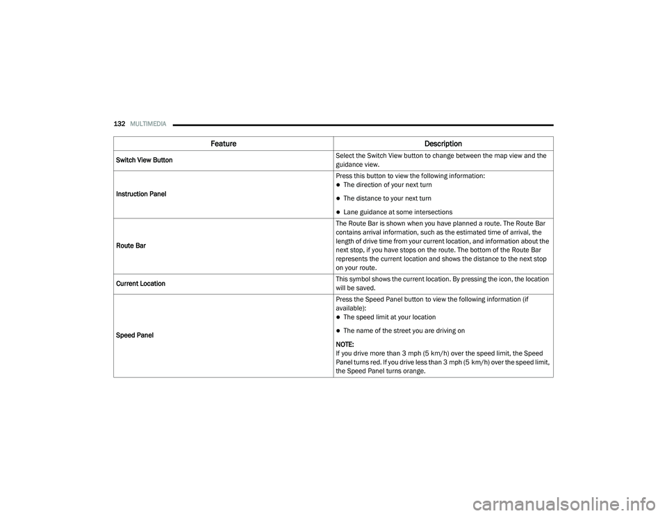
Feature Description
Switch View Button Select the Switch View button to change between the map view and the
guidance view.
Instruction Panel Press this button to view the following information:
The direction of your next turn
The distance to your next turn
Lane guidance at some intersections
Route Bar The Route Bar is shown when you have planned a route. The Route Bar
contains arrival information, such as the estimated time of arrival, the
length of drive time from your current location, and information about the
next stop, if you have stops on the route. The bottom of the Route Bar
represents the current location and shows the distance to the next stop
on your route.
Current Location This symbol shows the current location. By pressing the icon, the location
will be saved.
Speed Panel Press the Speed Panel button to view the following information (if
available):
The speed limit at your location
The name of the street you are driving on
NOTE:
If you drive more than 3 mph (5 km/h) over the speed limit, the Speed
Panel turns red. If you drive less than 3 mph (5 km/h) over the speed limit,
the Speed Panel turns orange.
21_VM_OM_EN_USC_t.book Page 132