2021 RAM PROMASTER CITY heater
[x] Cancel search: heaterPage 5 of 280

3
INSTRUMENT CLUSTER DISPLAY ......................44 Location And Controls ................................. 45
Change Engine Oil — If Equipped................ 46
Instrument Cluster Display Menu Items..... 46
TRIP COMPUTER ...................................................47
Trip Button.................................................... 48
Trip Functions ............................................. 48
Values Displayed ......................................... 49
WARNING LIGHTS AND MESSAGES ..................49
Red Warning Lights...................................... 49
Yellow Warning Lights ................................. 52
Green Indicator Lights ................................. 55
Blue Indicator Lights .................................... 56
ONBOARD DIAGNOSTIC SYSTEM — OBD II .......56
Onboard Diagnostic System (OBD II)
Cybersecurity................................................ 56
EMISSIONS INSPECTION AND MAINTENANCE
PROGRAMS ...........................................................57
STARTING AND OPERATING
STARTING THE ENGINE .......................................58
Automatic Transmission .............................. 58
Normal Starting ............................................ 58
Cold Weather Operation ............................. 58
Extended Park Starting................................ 58
If Engine Fails To Start ................................ 59
After Starting ................................................ 59
ENGINE BLOCK HEATER — IF EQUIPPED ...........59
ENGINE BREAK-IN RECOMMENDATIONS .........60
PARKING BRAKE .................................................60 AUTOMATIC TRANSMISSION ............................. 62
Key Ignition Park Interlock .......................... 62
Brake/Transmission Shift Interlock (BTSI)
System ......................................................... 63 Nine-Speed Automatic Transmission ........ 63
POWER STEERING .............................................. 67
Power Steering Fluid Check ....................... 68
CRUISE CONTROL — IF EQUIPPED ..................... 68
To Activate.................................................... 69
To Set A Desired Speed............................... 69
To Vary The Speed Setting .......................... 69
To Accelerate For Passing ........................... 69
To Resume Speed ....................................... 70
To Deactivate .............................................. 70
PARKSENSE REAR PARK ASSIST —
IF EQUIPPED ......................................................... 70
ParkSense Rear Park Assist Sensors ......... 70
ParkSense Rear Park Assist Alerts ............. 71
ParkSense Rear Park Assist Failure
Indications.................................................... 72 Cleaning The ParkSense Rear Park Assist
System .......................................................... 72 ParkSense Rear Park Assist System Usage
Precautions .................................................. 72
PARKVIEW REAR BACK UP CAMERA ............... 73
REFUELING THE VEHICLE ................................... 74 VEHICLE LOADING ................................................75
Vehicle Certification Label .......................... 75
Gross Vehicle Weight Rating (GVWR) ......... 76
Gross Axle Weight Rating (GAWR) ............. 76
Tire Size ........................................................ 76
Rim Size ....................................................... 76
Inflation Pressure ........................................ 76
Curb Weight ................................................. 76
Overloading .................................................. 76
Loading......................................................... 76
TRAILER TOWING .................................................77
Common Towing Definitions ....................... 77
Trailer Hitch Classification .......................... 78
Trailer Towing Weights (Maximum Trailer
Weight Ratings) ........................................... 79 Trailer And Tongue Weight ......................... 79
Towing Requirements ................................ 79
Towing Tips ................................................. 82
RECREATIONAL TOWING (BEHIND
MOTORHOME) ......................................................83
Towing This Vehicle Behind Another
Vehicle .......................................................... 83 Recreational Towing — Automatic
Transmission................................................ 83
DRIVING TIPS ........................................................84
Driving On Slippery Surfaces ..................... 84
Driving Through Water ............................... 84
21_VM_OM_EN_USC_t.book Page 3
Page 9 of 280

7
SYMBOLS KEY
If you do not read this entire Owner's Manual, you may miss important
information. Observe all Cautions and Warnings.
VAN CONVERSIONS/CAMPERS
The New Vehicle Limited Warranty does not apply to body modifications or
special equipment installed by van conversion/camper manufacturers/
body builders. U.S. residents refer to the Warranty Information, Section
2.1.C. Canadian residents refer to the “What Is Not Covered” section of
the Warranty Information. Such equipment includes video monitors, DVD/
Blu-ray™, heaters, stoves, refrigerators, etc. For warranty coverage and
service on these items, contact the applicable manufacturer.
Operating instructions for the special equipment installed by the
conversion/camper manufacturer should also be supplied with your
vehicle. If these instructions are missing, please contact an authorized
dealer for assistance in obtaining replacement documents from the
applicable manufacturer.
For information on the Body Builder’s Guide refer to
www.rambodybuilder.com. This website contains dimensional and
technical specifications for your vehicle. It is intended for Second Stage
Manufacturer's technical support. For service issues, contact an
authorized dealer.
VEHICLE MODIFICATIONS/ALTERATIONS
WARNING!These statements are against operating
procedures that could result in a collision,
bodily injury and/or death.
CAUTION! These statements are against procedures that
could result in damage to your vehicle.
NOTE: A suggestion which will improve installation,
operation, and reliability. If not followed, may
result in damage.
TIP: General ideas/solutions/suggestions on easier
use of the product or functionality.
PAGE REFERENCE
ARROW
Follow this reference for additional information
on a particular feature.
FOOTNOTE Supplementary and relevant information
pertaining to the topic.
WARNING!
Any modifications or alterations to this vehicle could seriously affect its
roadworthiness and safety and may lead to a collision resulting in
serious injury or death.
1
21_VM_OM_EN_USC_t.book Page 7
Page 23 of 280

GETTING TO KNOW YOUR VEHICLE21
HEAD RESTRAINTS
Head restraints are designed to reduce the risk
of injury by restricting head movement in the
event of a rear impact. Head restraints should
be adjusted so that the top of the head restraint
is located above the top of your ear.
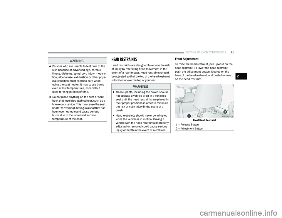
Front Adjustment
To raise the head restraint, pull upward on the
head restraint. To lower the head restraint,
push the adjustment button, located on the
base of the head restraint, and push downward
on the head restraint.
Front Head Restraint
WARNING!
Persons who are unable to feel pain to the
skin because of advanced age, chronic
illness, diabetes, spinal cord injury, medica -
tion, alcohol use, exhaustion or other phys -
ical condition must exercise care when
using the seat heater. It may cause burns
even at low temperatures, especially if
used for long periods of time.
Do not place anything on the seat or seat -
back that insulates against heat, such as a
blanket or cushion. This may cause the seat
heater to overheat. Sitting in a seat that has
been overheated could cause serious
burns due to the increased surface
temperature of the seat.
WARNING!
All occupants, including the driver, should
not operate a vehicle or sit in a vehicle’s
seat until the head restraints are placed in
their proper positions in order to minimize
the risk of neck injury in the event of a
crash.
Head restraints should never be adjusted
while the vehicle is in motion. Driving a
vehicle with the head restraints improperly
adjusted or removed could cause serious
injury or death in the event of a collision.
1 — Release Button
2 — Adjustment Button
2
21_VM_OM_EN_USC_t.book Page 21
Page 35 of 280

GETTING TO KNOW YOUR VEHICLE33
Bi-Level Mode
Air comes from the instrument panel
outlets and floor outlets. A slight
amount of air is directed through the
defrost and side window demister
outlets.
NOTE:
Bi-Level mode is designed under comfort condi -
tions to provide cooler air out of the panel
outlets and warmer air from the floor outlets.
Floor Mode
Air comes from the floor outlets. A
slight amount of air is directed
through the defrost and side window
demister outlets.
Mix Mode
Air is directed through the floor,
defrost, and side window demister
outlets. This setting works best in cold
or snowy conditions that require extra
heat to the windshield. This setting is good for
maintaining comfort while reducing moisture on
the windshield.
Operating Tips
NOTE:
Refer to the chart at the end of this section for
suggested control settings for various weather
conditions.
Summer Operation
The engine cooling system must be protected
with a high-quality antifreeze coolant to provide
proper corrosion protection and to protect
against engine overheating. OAT coolant
(conforming to MS.90032) is recommended
Ú page 259.
Winter Operation
To ensure the best possible heater and
defroster performance, make sure the engine
cooling system is functioning properly and the
proper amount, type, and concentration of
coolant is used Ú page 259. Use of the Air
Recirculation mode during Winter months is not
recommended because it may cause window
fogging.
Vacation/Storage
Any time you store your vehicle or keep it out of
service (i.e., vacation) for two weeks or more,
run the air conditioning system at idle for about
five minutes in fresh air with the blower setting
on high. This will ensure adequate system
lubrication to minimize the possibility of
compressor damage when the system is started
again.
Window Fogging
Vehicle windows tend to fog on the inside of the
glass in mild, rainy and/or humid weather. To
clear the windows, select Defrost or Mix mode
and increase the front blower speed. Do not use
the Recirculation mode without A/C for long
periods, as fogging may occur.
2
21_VM_OM_EN_USC_t.book Page 33
Page 60 of 280

58
STARTING AND OPERATING
STARTING THE ENGINE
Before starting your vehicle, adjust your seat,
adjust both inside and outside mirrors, and
fasten your seat belts.
Automatic Transmission
The gear selector must be in the PARK (P) or
NEUTRAL (N) position before you can start the
engine. Press the brake pedal before shifting to
any driving gear.
NOTE:
You must press the brake pedal before shifting
out of PARK.
Normal Starting
Turn the ignition switch to the AVV (START)
position and release it when the engine starts.
If the engine fails to start within 10 seconds,
turn the ignition switch to the STOP (OFF/LOCK)
position, wait 10 to 15 seconds, then repeat
this procedure.
Cold Weather Operation
To ensure reliable starting at low temperatures,
use of an externally powered electric engine
block heater (available from an authorized
dealer) is recommended.To prevent possible engine damage while
starting at low temperatures, this vehicle will
inhibit engine cranking when the ambient
temperature is less than -31°F (-35° C) and the
oil temperature sensor reading indicates an
engine block heater has not been used. The
message “plug in engine heater” will be
displayed in the instrument cluster when the
ambient temperature is below -25°F (-32° C) at
the time the engine is shut off as a reminder.
Extended Park Starting
NOTE:
Extended Park condition occurs when the
vehicle has not been started or driven for at
least 30 days.
1. Install a battery charger or jumper cables
to the battery to ensure a full battery
charge during the crank cycle.
2. Place the ignition in the AVV (START) position and release it when the engine
starts.
WARNING!
Never leave children alone in a vehicle, or
with access to an unlocked vehicle.
Allowing children to be in a vehicle unat -
tended is dangerous for a number of
reasons. A child or others could be seriously
or fatally injured. Children should be
warned not to touch the parking brake,
brake pedal or the transmission gear
selector.
Do not leave the key fob in or near the
vehicle (or in a location accessible to chil -
dren). A child could operate power
windows, other controls, or move the
vehicle.
21_VM_OM_EN_USC_t.book Page 58
Page 61 of 280

STARTING AND OPERATING59
3. If the engine fails to start within ten
seconds, place the ignition in the STOP
(OFF/LOCK) position, wait five seconds to
allow the starter to cool, then repeat the
Extended Park Starting procedure.
4. If the engine fails to start after eight attempts, allow the starter to cool for at
least 10 minutes, then repeat the
procedure.
If Engine Fails To Start
If the engine fails to start after you have
followed the “Normal Starting” or “Extreme Cold
Weather” procedure, and has not experienced
an extended park condition as identified in
“Extended Park Starting” procedure, it may be
flooded. Push the accelerator pedal all the way
to the floor and hold it there. Crank the engine
for no more than 15 seconds. This should clear
any excess fuel in case the engine is flooded. Leave the ignition key in the MAR (ON/RUN)
position, release the accelerator pedal and
repeat the “Normal Starting” procedure.
After Starting
The idle speed is controlled automatically, and
it will decrease as the engine warms up.
ENGINE BLOCK HEATER — IF EQUIPPED
The engine block heater warms the engine and
permits quicker starts in cold weather.
Connect the cord to a 110-115 Volt AC electrical
outlet with a grounded, three-wire extension
cord.
For ambient temperatures below 0°F (-18°C),
the engine block heater is recommended. For
ambient temperatures below -20°F (-29°C),
the engine block heater is required.
The engine block heater cord is routed under
the hood, behind to the driver’s side headlamp.
Follow the steps below to properly use the
engine block heater:
CAUTION!
To prevent damage to the starter, do not
crank continuously for more than 10 seconds
at a time. Wait 10 to 15 seconds before trying
again.
WARNING!
Never pour fuel or other flammable liquid
into the throttle body air inlet opening in an
attempt to start the vehicle. This could
result in flash fire causing serious personal
injury.
Do not attempt to push or tow your vehicle
to get it started. Vehicles equipped with an
automatic transmission cannot be started
this way. Unburned fuel could enter the
catalytic converter and once the engine has
started, ignite and damage the converter
and vehicle.
If the vehicle has a discharged battery,
booster cables may be used to obtain a
start from a booster battery or the battery in
another vehicle. This type of start can be
dangerous if done improperly
Úpage 204.
CAUTION!
To prevent damage to the starter, do not
continuously crank the engine for more than
25 seconds at a time. Wait 60 seconds
before trying again.
4
21_VM_OM_EN_USC_t.book Page 59
Page 62 of 280

60STARTING AND OPERATING
1. Locate the engine block heater cord
(behind the driver’s side headlamp).
2. Undo the hook-and-loop strap that secures the heater cord in place.
3. Pull the cord to the front of the vehicle and plug it into a grounded, three-wire extension
cord.
4. After the vehicle is running, reattach the cord to the hook-and-loop strap and
properly stow away behind the driver’s side
headlamp.
NOTE:
The engine block heater cord is a factory
installed option. If your vehicle is not
equipped, heater cords are available from an
authorized Mopar dealer.
The engine block heater will require 110 Volts
AC and 6.5 Amps to activate the heater
element.
The engine block heater must be plugged in
at least one hour to have an adequate
warming effect on the engine.
ENGINE BREAK-IN RECOMMENDATIONS
A long break-in period is not required for the
engine and drivetrain (transmission and axle) in
your vehicle.
Drive moderately during the first 300 miles
(500 km). After the initial 60 miles (100 km),
speeds up to 50 or 55 mph (80 or 90 km/h) are
desirable.
While cruising, brief full-throttle acceleration
within the limits of local traffic laws contributes
to a good break-in. Wide-open throttle
acceleration in low gear can be detrimental and
should be avoided.
The engine oil installed in the engine at the
factory is a high-quality energy conserving type
lubricant. Oil changes should be consistent with
anticipated climate conditions under which
vehicle operations will occur. For the
recommended viscosity and quality grades
Ú page 259. NOTE:
A new engine may consume some oil during its
first few thousand miles (kilometers) of opera
-
tion. This should be considered a normal part of
the break-in and not interpreted as a concern.
Please check your oil level with the engine oil
indicator often during the break in period. Add
oil as required.
PARKING BRAKE
Before leaving the vehicle, make sure that the
parking brake is fully applied. Also, be certain to
leave an automatic transmission in PARK.
The parking brake lever is located in the center
console. To apply the parking brake, pull the
lever up as firmly as possible. To release the
parking brake, pull the lever up slightly, push
the center button, then lower the lever
completely.
WARNING!
Remember to disconnect the engine block
heater cord before driving. Damage to the
110-115 Volt electrical cord could cause
electrocution.
CAUTION!
Never use Non-Detergent Oil or Straight
Mineral Oil in the engine or damage may
result.
21_VM_OM_EN_USC_t.book Page 60
Page 170 of 280

168SAFETY
Enhanced Accident Response System
In the event of an impact, if the communication
network remains intact, and the power remains
intact, depending on the nature of the event,
the Occupant Restraint Controller (ORC) will
determine whether to have the Enhanced
Accident Response System perform the
following functions:
Cut off fuel to the engine (if equipped)
Cut off battery power to the electric motor (if
equipped)
Flash hazard lights as long as the battery has
power
Turn on the interior lights, which remain on
as long as the battery has power or for
15 minutes from the intervention of the
Enhanced Accident Response System
Unlock the power door locks
Your vehicle may also be designed to perform
any of these other functions in response to the
Enhanced Accident Response System:
Turn off the Fuel Filter Heater, Turn off the
HVAC Blower Motor, Close the HVAC Circula -
tion Door
Cut off battery power to the:
Engine
Electric Motor (if equipped)
Electric Power Steering
Brake booster
Electric park brake
Automatic transmission gear selector
Horn
Front wiper
Headlamp washer pump
NOTE:
After an accident, remember to cycle the igni -
tion to the STOP/OFF position and remove the
key from the ignition switch to avoid draining
the battery. Carefully check the vehicle for fuel
leaks in the engine compartment and on the
ground near the engine compartment and fuel
tank before resetting the system and starting
the engine. If there are no fuel leaks or damage
to the vehicle electrical devices (e.g. headlights)
after an accident, reset the system by following
the procedure described below. If you have any
doubt, contact an authorized dealer.
Enhanced Accident Response System Reset
Procedure
In order to reset the Enhanced Accident
Response System functions after an event, the
ignition switch must be changed from ignition
AVV/START or MAR/RUN to ignition STOP/OFF.
Carefully check the vehicle for fuel leaks in the
engine compartment and on the ground near
the engine compartment and fuel tank before
resetting the system and starting the engine.
After a crash, if the vehicle will not start after
performing the reset procedure, the vehicle
must be towed to an authorized dealer to be
inspected and to have the Enhanced Accident
Response System reset.
21_VM_OM_EN_USC_t.book Page 168