2021 ALFA ROMEO STELVIO battery
[x] Cancel search: batteryPage 92 of 280
STARTING AND OPERATING
90
For the first 1,500 miles (2,414 km):
Do not participate in track events, sport
driving schools, or similar activities during
the first 1,500 miles (2,414 km).
NOTE:
Monitor engine oil with every refueling and add
if necessary. Oil and fuel consumption may be
higher through the first oil change interval.
ELECTRIC PARK BRAKE (EPB)
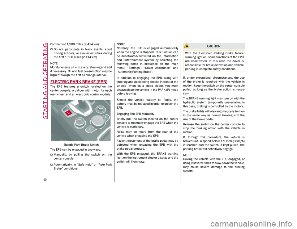
The EPB features a switch located on the
center console, a caliper with motor for each
rear wheel, and an electronic control module.
Electric Park Brake Switch
The EPB can be engaged in two ways:
Manually, by pulling the switch on the
center console.
Automatically, in “Safe Hold” or “Auto Park
Brake” conditions.
NOTE:
Normally, the EPB is engaged automatically
when the engine is stopped. This function can
be deactivated/activated on the Information
and Entertainment system by selecting the
following items in sequence on the main
menu: “Settings”, “Driver Assistance” and
“Automatic Parking Brake”.
In addition to engaging the EPB, along with
steering and positioning chocks in front of the
wheels (when on a steep slope), you must
always place the vehicle in the PARK (P) mode
before leaving.
Should the vehicle battery be faulty, the
battery must be replaced in order to unlock the
EPB.
Engaging The EPB Manually
Briefly pull the switch located on the center
console to manually engage the EPB when the
vehicle is stationary.
Noise may be heard from the rear of the
vehicle when engaging the EPB.
A slight movement of the brake pedal may be
detected when engaging the EPB with the
brake pedal pressed.
With the EPB engaged, the BRAKE warning
light on the instrument cluster display and the
switch will illuminate.
If, under exceptional circumstances, the use
of the brake is required with the vehicle in
motion, keep the switch on the center console
pulled as long as the brake action is neces
-
sary.
The BRAKE warning light may turn on with the
hydraulic system temporarily unavailable; in
this case, braking is controlled by the motors.
The brake lights will also automatically turn on
in the same way as normal braking with the
use of the brake pedal.
Release the switch on the center console to
stop the braking action with the vehicle in
motion.
If, through this procedure, the vehicle is
braked until a speed below 1.9 mph (3 km/h)
is reached and the switch is kept pulled, the
parking brake will definitively engage.
NOTE:
Driving the vehicle with the EPB engaged, or
using it several times to slow down the vehicle,
may cause severe damage to the braking
system.
CAUTION!
With the Electronic Parking Brake failure
warning light on, some functions of the EPB
are deactivated. In this case the driver is
responsible for brake activation and vehicle
parking in complete safety conditions.
21_GU_OM_EN_USC_t.book Page 90
Page 104 of 280
STARTING AND OPERATING
102
System Manual Activation/Deactivation
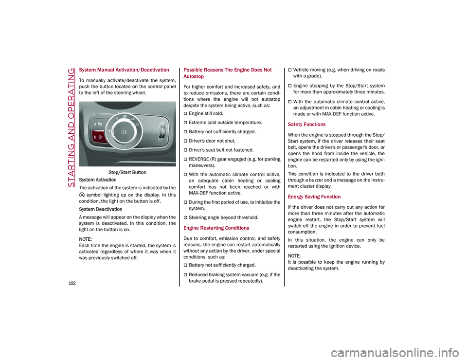
To manually activate/deactivate the system,
push the button located on the control panel
to the left of the steering wheel.Stop/Start Button
System Activation
The activation of the system is indicated by the symbol lighting up on the display. In this
condition, the light on the button is off.
System Deactivation
A message will appear on the display when the
system is deactivated. In this condition, the
light on the button is on.
NOTE:
Each time the engine is started, the system is
activated regardless of where it was when it
was previously switched off.
Possible Reasons The Engine Does Not
Autostop
For higher comfort and increased safety, and
to reduce emissions, there are certain condi -
tions where the engine will not autostop
despite the system being active, such as:
Engine still cold.
Extreme cold outside temperature.
Battery not sufficiently charged.
Driver's door not shut.
Driver's seat belt not fastened.
REVERSE (R) gear engaged (e.g. for parking
maneuvers).
With the automatic climate control active,
an adequate cabin heating or cooling
comfort has not been reached or with
MAX-DEF function active.
During the first period of use, to initialize the
system.
Steering angle beyond threshold.
Engine Restarting Conditions
Due to comfort, emission control, and safety
reasons, the engine can restart automatically
without any action by the driver, under special
conditions, such as:
Battery not sufficiently charged.
Reduced braking system vacuum (e.g. if the
brake pedal is pressed repeatedly).
Vehicle moving (e.g. when driving on roads
with a grade).
Engine stopping by the Stop/Start system
for more than approximately three minutes.
With the automatic climate control active,
an adjustment in cabin heating or cooling is
made or with MAX-DEF function active.
Safety Functions
When the engine is stopped through the Stop/
Start system, if the driver releases their seat
belt, opens the driver's or passenger's door, or
opens the hood from inside the vehicle, the
engine can be restarted only by using the igni -
tion.
This condition is indicated to the driver both
through a buzzer and a message on the instru-
ment cluster display.
Energy Saving Function
If the driver does not carry out any action for
more than three minutes after the automatic
engine restart, the Stop/Start system will
switch off the engine in order to prevent fuel
consumption.
In this situation, the engine can only be
restarted using the ignition device.
NOTE:
It is possible to keep the engine running by
deactivating the system.
21_GU_OM_EN_USC_t.book Page 102
Page 105 of 280
103
Irregular Operation
In the event of malfunction, the Stop/Start
system is deactivated.
For failure indications
Ú
page 74.
Vehicle Inactivity
In the event of vehicle inactivity (or if the
battery is replaced), special attention must be
paid to the disconnection of the battery power
supply.
Proceed as follows:
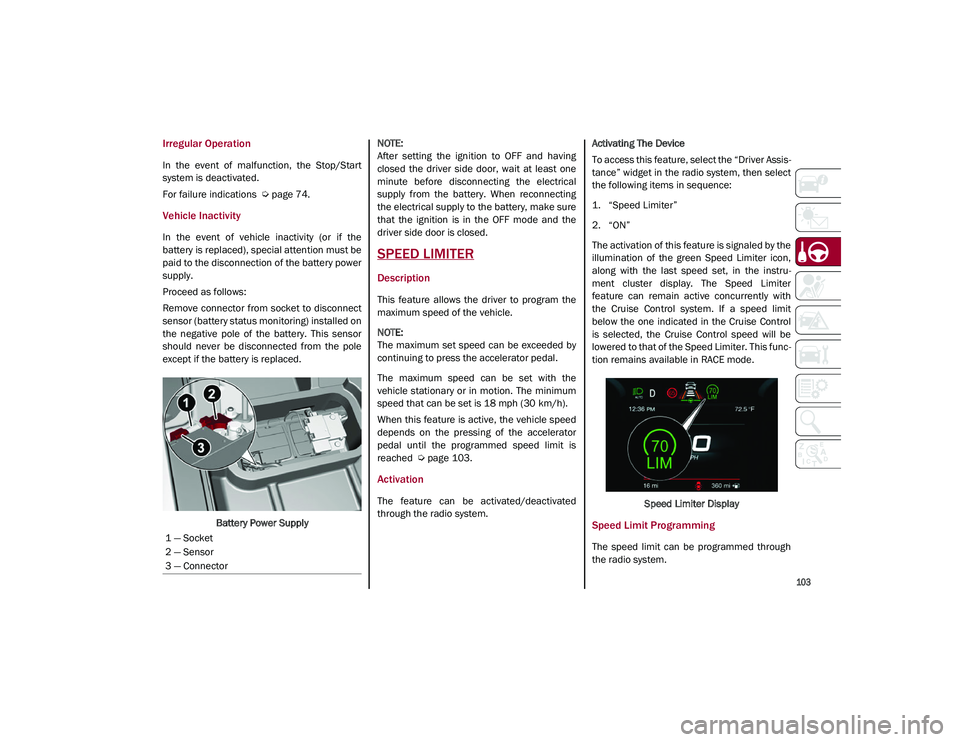
Remove connector from socket to disconnect
sensor (battery status monitoring) installed on
the negative pole of the battery. This sensor
should never be disconnected from the pole
except if the battery is replaced.
Battery Power Supply
NOTE:
After setting the ignition to OFF and having
closed the driver side door, wait at least one
minute before disconnecting the electrical
supply from the battery. When reconnecting
the electrical supply to the battery, make sure
that the ignition is in the OFF mode and the
driver side door is closed.
SPEED LIMITER
Description
This feature allows the driver to program the
maximum speed of the vehicle.
NOTE:
The maximum set speed can be exceeded by
continuing to press the accelerator pedal.
The maximum speed can be set with the
vehicle stationary or in motion. The minimum
speed that can be set is 18 mph (30 km/h).
When this feature is active, the vehicle speed
depends on the pressing of the accelerator
pedal until the programmed speed limit is
reached
Ú
page 103.
Activation
The feature can be activated/deactivated
through the radio system. Activating The Device
To access this feature, select the “Driver Assis
-
tance” widget in the radio system, then select
the following items in sequence:
1. “Speed Limiter”
2. “ON”
The activation of this feature is signaled by the
illumination of the green Speed Limiter icon,
along with the last speed set, in the instru -
ment cluster display. The Speed Limiter
feature can remain active concurrently with
the Cruise Control system. If a speed limit
below the one indicated in the Cruise Control
is selected, the Cruise Control speed will be
lowered to that of the Speed Limiter. This func -
tion remains available in RACE mode.
Speed Limiter Display
Speed Limit Programming
The speed limit can be programmed through
the radio system.
1 — Socket
2 — Sensor
3 — Connector
21_GU_OM_EN_USC_t.book Page 103
Page 142 of 280
STARTING AND OPERATING
140
Towing Requirements — Trailer Brakes
Do not interconnect the hydraulic brake
system or vacuum system of your vehicle
with that of the trailer. This could cause
inadequate braking and possible personal
injury.
An electronically actuated trailer brake
controller is required when towing a trailer
with electronically actuated brakes. When
towing a trailer equipped with a hydraulic
surge actuated brake system, an electronic
brake controller is not required.
Trailer brakes are recommended for trailers
over 1,000 lbs (453 kg) and required for
trailers in excess of 2,000 lbs (907 kg).
Towing Requirements — Trailer Lights And
Wiring
Whenever you pull a trailer, regardless of the
trailer size, stoplights and turn signals on the
trailer are required for motoring safety.
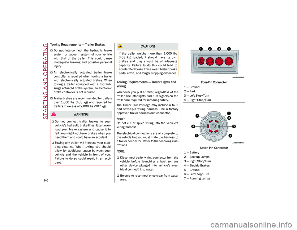
The Trailer Tow Package may include a four-
and seven-pin wiring harness. Use a factory
approved trailer harness and connector.
NOTE:
Do not cut or splice wiring into the vehicle’s
wiring harness.
The electrical connections are all complete to
the vehicle but you must mate the harness to
a trailer connector. Refer to the following illus -
trations.
NOTE:
Disconnect trailer wiring connector from the
vehicle before launching a boat (or any
other device plugged into vehicle’s elec -
trical connect) into water.
Be sure to reconnect once clear from water
area. Four-Pin Connector
Seven-Pin Connector
WARNING!
Do not connect trailer brakes to your
vehicle's hydraulic brake lines. It can over -
load your brake system and cause it to
fail. You might not have brakes when you
need them and could have an accident.
Towing any trailer will increase your stop -
ping distance. When towing, you should
allow for additional space between your
vehicle and the vehicle in front of you.
Failure to do so could result in an acci -
dent.
CAUTION!
If the trailer weighs more than 1,000 lbs
(453 kg) loaded, it should have its own
brakes and they should be of adequate
capacity. Failure to do this could lead to
accelerated brake lining wear, higher brake
pedal effort, and longer stopping distances.
1 — Ground
2 — Park
3 — Left Stop/Turn
4 — Right Stop/Turn
1 — Battery
2 — Backup Lamps
3 — Right Stop/Turn
4 — Electric Brakes
5 — Ground
6 — Left Stop/Turn
7 — Running Lamps
21_GU_OM_EN_USC_t.book Page 140
Page 171 of 280
169
Supplemental Restraint Systems (SRS)
Some of the safety features described in this
section may be standard equipment on some
models, or may be optional equipment on
others. If you are not sure, ask an authorized
dealer.
The air bag system must be ready to protect
you in a collision. The Occupant Restraint
Controller (ORC) monitors the internal circuits
and interconnecting wiring associated with the
electrical Air Bag System Components. Your
vehicle may be equipped with the following Air
Bag System Components:
Air Bag System Components
Occupant Restraint Controller (ORC)
Air Bag Warning Light
Steering Wheel and Column
Instrument Panel
Knee Impact Bolsters
Driver and Front Passenger Air Bags
Seat Belt Buckle Switch
Supplemental Side Air Bags
Supplemental Knee Air Bags
Front and Side Impact Sensors
Seat Belt Pretensioners
Seat Track Position Sensors
Air Bag Warning Light
The Occupant Restraint Controller
(ORC) monitors the readiness of the
electronic parts of the air bag system
whenever the ignition switch is in the
START or ON/RUN position. If the ignition
switch is in the OFF position or in the ACC posi -
tion, the air bag system is not on and the air
bags will not inflate.
The ORC contains a backup power supply
system that may deploy the air bag system
even if the battery loses power or it becomes
disconnected prior to deployment.
The ORC turns on the Air Bag Warning Light in
the instrument panel for approximately four to
eight seconds for a self-check when the igni -
tion switch is first in the ON/RUN position.
After the self-check, the Air Bag Warning Light
will turn off. If the ORC detects a malfunction
in any part of the system, it turns on the Air
Bag Warning Light, either momentarily or continuously. A single chime will sound to alert
you if the light comes on again after initial
startup.
The ORC also includes diagnostics that will illu
-
minate the instrument panel Air Bag Warning
Light if a malfunction is detected that could
affect the air bag system. The diagnostics also
record the nature of the malfunction. While
the air bag system is designed to be mainte -
nance free, if any of the following occurs, have
an authorized dealer service the air bag
system immediately.The Air Bag Warning Light does not come on
during the four to eight seconds when the
ignition switch is first in the ON/RUN posi -
tion.
The Air Bag Warning Light remains on after
the four to eight-second interval.
The Air Bag Warning Light comes on inter-
mittently or remains on while driving.
NOTE:
If the speedometer, tachometer, or any engine
related gauges are not working, the Occupant
Restraint Controller (ORC) may also be
disabled. In this condition the air bags may not
be ready to inflate for your protection. Have an
authorized dealer service the air bag system
immediately.
Do not use the Automatic Locking Mode to
restrain occupants who are wearing the
seat belt or children who are using booster
seats. The locked mode is only used to
install rear-facing or forward-facing child
restraints that have a harness for
restraining the child.
WARNING! (Continued)
21_GU_OM_EN_USC_t.book Page 169
Page 177 of 280
175
If A Deployment Occurs
The front air bags are designed to deflate
immediately after deployment.
NOTE:
Front and/or side air bags will not deploy in all
collisions. This does not mean something is
wrong with the air bag system.
If you do have a collision which deploys the air
bags, any or all of the following may occur:
The air bag material may sometimes cause
abrasions and/or skin reddening to the
occupants as the air bags deploy and
unfold. The abrasions are similar to friction
rope burns or those you might get sliding
along a carpet or gymnasium floor. They are
not caused by contact with chemicals. They
are not permanent and normally heal
quickly. However, if you haven’t healed
significantly within a few days, or if you have
any blistering, see your doctor immediately.
As the air bags deflate, you may see some
smoke-like particles. The particles are a
normal by-product of the process that
generates the non-toxic gas used for air bag
inflation. These airborne particles may irri-
tate the skin, eyes, nose, or throat. If you
have skin or eye irritation, rinse the area
with cool water. For nose or throat irritation,
move to fresh air. If the irritation continues,
see your doctor. If these particles settle on
your clothing, follow the garment manufac -
turer’s instructions for cleaning. Do not drive your vehicle after the air bags
have deployed. If you are involved in another
collision, the air bags will not be in place to
protect you.
NOTE:
Air bag covers may not be obvious in the
interior trim, but they will open during air
bag deployment.
After any collision, the vehicle should be
taken to an authorized dealer immediately.
Enhanced Accident Response System
In the event of an impact, if the communica
-
tion network remains intact, and the power
remains intact, depending on the nature of the
event, the Occupant Restraint Controller (ORC)
will determine whether to have the Enhanced
Accident Response System perform the
following functions:
Cut off fuel to the engine (if equipped)
Cut off battery power to the electric motor (if
equipped)
Flash hazard lights as long as the battery
has power
Turn on the interior lights, which remain on
as long as the battery has power or for
15 minutes from the intervention of the
Enhanced Accident Response System
Unlock the power door locks
Your vehicle may also be designed to perform
any of these other functions in response to the
Enhanced Accident Response System:
Turn off the Fuel Filter Heater, Turn off the
HVAC Blower Motor, Close the HVAC Circula -
tion Door
Cut off battery power to the:
• Engine
• Electric Motor (if equipped)
• Electric power steering
• Brake booster
• Electric park brake
• Automatic transmission gear selector
• Horn
• Front wiper
• Headlamp washer pump
WARNING!
Deployed air bags and seat belt
pretensioners cannot protect you in another
collision. Have the air bags, seat belt
pretensioners, and the seat belt retractor
assemblies replaced by an authorized
dealer immediately. Also, have the
Occupant Restraint Controller System
serviced as well.
21_GU_OM_EN_USC_t.book Page 175
Page 178 of 280
SAFETY
176
NOTE:
After an accident, remember to cycle the igni-
tion to the OFF position and remove the key
from the ignition switch to avoid draining the
battery. Carefully check the vehicle for fuel
leaks in the engine compartment and on the
ground near the engine compartment and fuel
tank before resetting the system and starting
the engine. If there are no fuel leaks or
damage to the vehicle electrical devices (e.g.
headlights) after an accident, reset the system by following the procedure described below. If
you have any doubt, contact an authorized
dealer.
Enhanced Accident Response System
Reset Procedure
After the event occurs, when the system is
active, a message regarding fuel cutoff is
displayed. Turn the ignition switch from igni
-
tion ACC or ON/RUN to ignition OFF. Carefully
check the vehicle for fuel leaks in the engine compartment and on the ground near the
engine compartment and fuel tank before
resetting the system and starting the engine.
Depending on the nature of the event the left
and right turn signal lights, located in the
instrument panel, may both be blinking and
will continue to blink. In order to move your
vehicle to the side of the road, you must follow
the system reset procedure.
Customer Action
NOTE:
Each step MUST BE held for at least two secondsCustomer Will See
1. Turn ignition OFF. (Turn Signal Switch Must be placed in
Neutral State).
2. Turn ignition ACC. Right turn light BLINKS.
Left turn light is OFF.
3. Turn right turn signal switch ON. Right turn light is ON SOLID.
Left turn light BLINKS.
4. Place turn signal in neutral state. Right turn light is OFF.
Left turn light BLINKS.
5. Turn left turn signal switch ON. Right turn light BLINKS.
Left turn light is ON SOLID.
6. Place turn signal in neutral state. Right turn light BLINKS.
Left turn light is OFF.
7. Turn right turn signal switch ON. Right turn light is ON SOLID.
Left turn light BLINKS.
8. Place turn signal in neutral state. Right turn light is OFF.
Left turn light BLINKS.
21_GU_OM_EN_USC_t.book Page 176
Page 194 of 280
192
IN CASE OF EMERGENCY
Have a flat tire or a burnt-out bulb?
At times, a problem such as these may inter-
fere with your driving experience.
The section on emergencies can help you to
deal with critical situations independently.
In an emergency, we recommend that you call
the phone number found in “Helpful
Addresses And Telephone Numbers” under
“How To Deal With Warranty Problems” in the
Warranty Book.
You may also consider contacting an autho -
rized dealer.
HAZARD WARNING FLASHERS
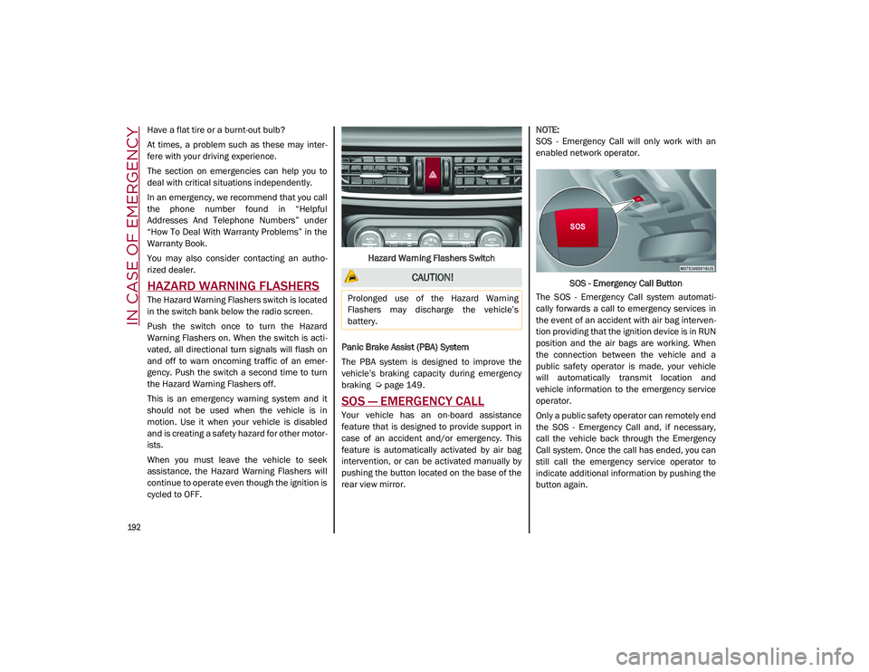
The Hazard Warning Flashers switch is located
in the switch bank below the radio screen.
Push the switch once to turn the Hazard
Warning Flashers on. When the switch is acti -
vated, all directional turn signals will flash on
and off to warn oncoming traffic of an emer -
gency. Push the switch a second time to turn
the Hazard Warning Flashers off.
This is an emergency warning system and it
should not be used when the vehicle is in
motion. Use it when your vehicle is disabled
and is creating a safety hazard for other motor -
ists.
When you must leave the vehicle to seek
assistance, the Hazard Warning Flashers will
continue to operate even though the ignition is
cycled to OFF. Hazard Warning Flashers Switch
Panic Brake Assist (PBA) System
The PBA system is designed to improve the
vehicle’s braking capacity during emergency
braking
Ú
page 149.
SOS — EMERGENCY CALL
Your vehicle has an on-board assistance
feature that is designed to provide support in
case of an accident and/or emergency. This
feature is automatically activated by air bag
intervention, or can be activated manually by
pushing the button located on the base of the
rear view mirror.
NOTE:
SOS - Emergency Call will only work with an
enabled network operator.
SOS - Emergency Call Button
The SOS - Emergency Call system automati -
cally forwards a call to emergency services in
the event of an accident with air bag interven -
tion providing that the ignition device is in RUN
position and the air bags are working. When
the connection between the vehicle and a
public safety operator is made, your vehicle
will automatically transmit location and
vehicle information to the emergency service
operator.
Only a public safety operator can remotely end
the SOS - Emergency Call and, if necessary,
call the vehicle back through the Emergency
Call system. Once the call has ended, you can
still call the emergency service operator to
indicate additional information by pushing the
button again.
CAUTION!
Prolonged use of the Hazard Warning
Flashers may discharge the vehicle’s
battery.
21_GU_OM_EN_USC_t.book Page 192