2021 ALFA ROMEO STELVIO height adjustment
[x] Cancel search: height adjustmentPage 32 of 280
GETTING TO KNOW YOUR VEHICLE
30
DRIVER MEMORY SETTINGS — IF
EQUIPPED
This feature allows the driver to store up to
three different memory profiles for easy recall
through a memory switch. Each memory
profile saves desired position settings for the
following features:
Driver seat
Side mirrors
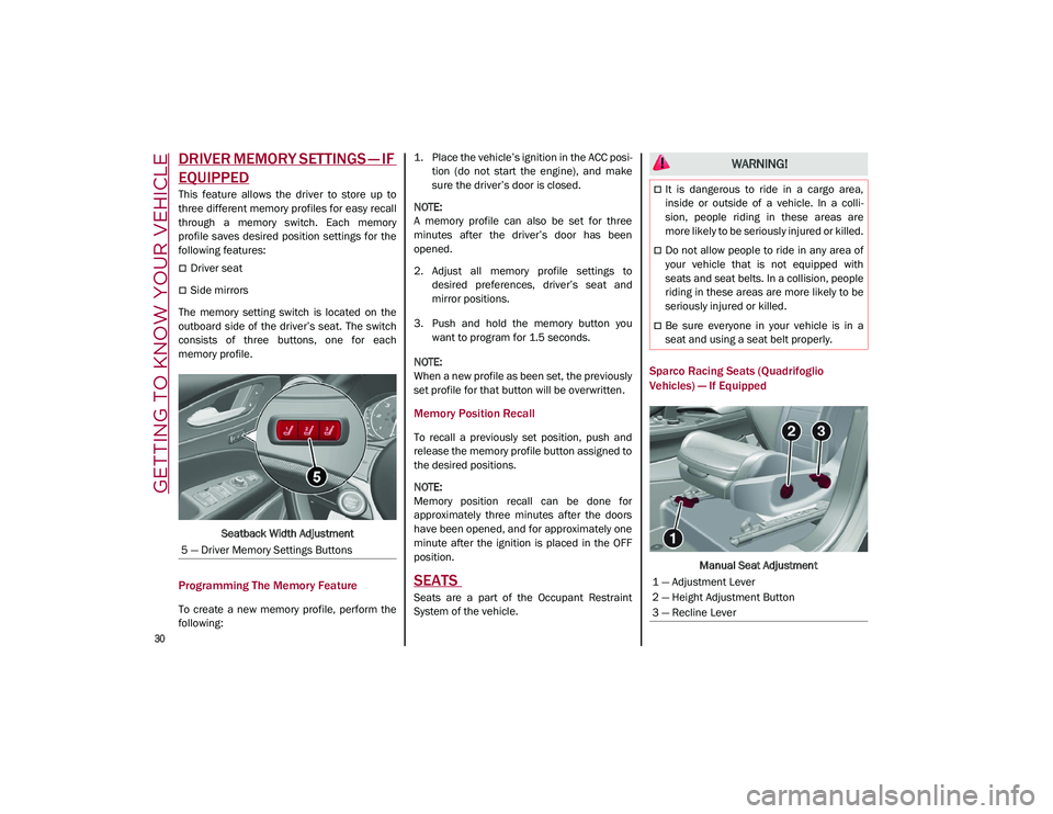
The memory setting switch is located on the
outboard side of the driver’s seat. The switch
consists of three buttons, one for each
memory profile.
Seatback Width Adjustment
Programming The Memory Feature
To create a new memory profile, perform the
following: 1. Place the vehicle’s ignition in the ACC posi
-
tion (do not start the engine), and make
sure the driver’s door is closed.
NOTE:
A memory profile can also be set for three
minutes after the driver’s door has been
opened.
2. Adjust all memory profile settings to desired preferences, driver’s seat and
mirror positions.
3. Push and hold the memory button you want to program for 1.5 seconds.
NOTE:
When a new profile as been set, the previously
set profile for that button will be overwritten.
Memory Position Recall
To recall a previously set position, push and
release the memory profile button assigned to
the desired positions.
NOTE:
Memory position recall can be done for
approximately three minutes after the doors
have been opened, and for approximately one
minute after the ignition is placed in the OFF
position.
SEATS
Seats are a part of the Occupant Restraint
System of the vehicle.
Sparco Racing Seats (Quadrifoglio
Vehicles) — If Equipped
Manual Seat Adjustment
5 — Driver Memory Settings Buttons
WARNING!
It is dangerous to ride in a cargo area,
inside or outside of a vehicle. In a colli
-
sion, people riding in these areas are
more likely to be seriously injured or killed.
Do not allow people to ride in any area of
your vehicle that is not equipped with
seats and seat belts. In a collision, people
riding in these areas are more likely to be
seriously injured or killed.
Be sure everyone in your vehicle is in a
seat and using a seat belt properly.
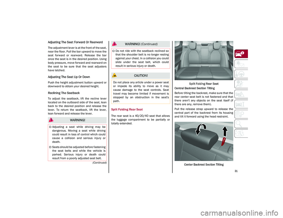
1 — Adjustment Lever
2 — Height Adjustment Button
3 — Recline Lever
21_GU_OM_EN_USC_t.book Page 30
Page 33 of 280
31
(Continued)
Adjusting The Seat Forward Or Rearward
The adjustment lever is at the front of the seat,
near the floor. Pull the bar upward to move the
seat forward or rearward. Release the bar
once the seat is in the desired position. Using
body pressure, move forward and rearward on
the seat to be sure that the seat adjusters
have latched.
Adjusting The Seat Up Or Down
Push the height adjustment button upward or
downward to obtain your desired height.
Reclining The Seatback
To adjust the seatback, lift the recline lever
located on the outboard side of the seat, lean
back to the desired position and release the
lever. To return the seatback, lift the lever,
lean forward and release the lever.
Split Folding Rear Seat
The rear seat is a 40/20/40 seat that allows
the luggage compartment to be partially or
totally extended.Split Folding Rear Seat
Central Backrest Section Tilting
Before tilting the backrest, make sure that the
rear center seat belt is not fastened and that
there aren't any objects on the seat itself (if
there are any, remove them).
Pull the release strap upward to release the
central part of the backrest from its housing
and tilt it forward using the head restraint.
Center Backrest Section Tilting
WARNING!
Adjusting a seat while driving may be
dangerous. Moving a seat while driving
could result in loss of control which could
cause a collision and serious injury or
death.
Seats should be adjusted before fastening
the seat belts and while the vehicle is
parked. Serious injury or death could
result from a poorly adjusted seat belt.
Do not ride with the seatback reclined so
that the shoulder belt is no longer resting
against your chest. In a collision you could
slide under the seat belt, which could
result in serious injury or death.
CAUTION!
Do not place any article under a power seat
or impede its ability to move as it may
cause damage to the seat controls. Seat
travel may become limited if movement is
stopped by an obstruction in the seat's
path.
WARNING! (Continued)
21_GU_OM_EN_USC_t.book Page 31
Page 35 of 280
33
Power Adjustment (Front Seats)
NOTE:
The seat layout may vary according to the
vehicle options.
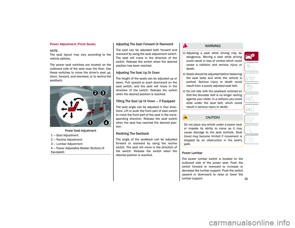
The power seat switches are located on the
outboard side of the seat near the floor. Use
these switches to move the driver's seat up,
down, forward, and rearward, or to recline the
seatback.Power Seat Adjustment
Adjusting The Seat Forward Or Rearward
The seat can be adjusted both forward and
rearward by using the seat adjustment switch.
The seat will move in the direction of the
switch. Release the switch when the desired
position has been reached.
Adjusting The Seat Up Or Down
The height of the seats can be adjusted up or
down. Pull upward or push downward on the
seat switch, and the seat will move in the
direction of the switch. Release the switch
when the desired position is reached.
Tilting The Seat Up Or Down — If Equipped
The seat angle can be adjusted in four direc -
tions. Lift or push the front part of seat switch
to move the front part of the seat in the corre -
sponding direction. Release the seat switch
when the seat has reached the desired posi -
tion.
Reclining The Seatback
The angle of the seatback can be adjusted
forward or rearward by using the recline
switch. The seat will move in the direction of
the switch. Release the switch when the
desired position is reached.
Power Lumbar
The power lumbar switch is located on the
outboard side of the power seat. Push the
switch forward or rearward to increase or
decrease the lumbar support. Push the switch
upward or downward to raise or lower the
lumbar support.
1 — Seat Adjustment
2 — Recline Adjustment
3 — Lumbar Adjustment
4 — Power Adjustable Bolster Buttons (If
Equipped)
WARNING!
Adjusting a seat while driving may be
dangerous. Moving a seat while driving
could result in loss of control which could
cause a collision and serious injury or
death.
Seats should be adjusted before fastening
the seat belts and while the vehicle is
parked. Serious injury or death could
result from a poorly adjusted seat belt.
Do not ride with the seatback reclined so
that the shoulder belt is no longer resting
against your chest. In a collision you could
slide under the seat belt, which could
result in serious injury or death.
CAUTION!
Do not place any article under a power seat
or impede its ability to move as it may
cause damage to the seat controls. Seat
travel may become limited if movement is
stopped by an obstruction in the seat's
path.
21_GU_OM_EN_USC_t.book Page 33
Page 38 of 280
GETTING TO KNOW YOUR VEHICLE
36
To lower the head restraint, push in the adjust-
ment button and lower the head restraint to
the desired height while holding the button.
Then, release the adjustment button.
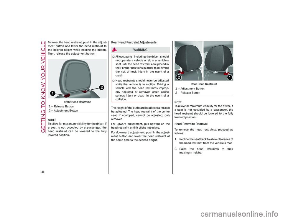
Front Head Restraint
NOTE:
To allow for maximum visibility for the driver, if
a seat is not occupied by a passenger, the
head restraint can be lowered to the fully
lowered position.Rear Head Restraint Adjustments
The height of the outboard head restraints can
be adjusted. The head restraint of the center
seat, if equipped, cannot be adjusted, only
removed.
For upward adjustment, pull upward on the
head restraint until it clicks into place.
For downward adjustment, push in the adjust -
ment button and lower the head restraint at
the same time to the desired height. Rear Head Restraint
NOTE:
To allow for maximum visibility for the driver, if
a seat is not occupied by a passenger, the
head restraint should be lowered to the fully
lowered position.
Head Restraint Removal
To remove the head restraints, proceed as
follows:
1. Recline the seat back to allow clearance of the head restraint from the vehicle’s roof.
2. Raise the head restraints to their maximum height.
1 — Release Button
2 — Adjustment Button
WARNING!
All occupants, including the driver, should
not operate a vehicle or sit in a vehicle’s
seat until the head restraints are placed in
their proper positions in order to minimize
the risk of neck injury in the event of a
crash.
Head restraints should never be adjusted
while the vehicle is in motion. Driving a
vehicle with the head restraints improp
-
erly adjusted or removed could cause
serious injury or death in the event of a
collision.
1 — Adjustment Button
2 — Release Button
21_GU_OM_EN_USC_t.book Page 36
Page 39 of 280
37
3. Push the adjustment button and therelease button at the side of the two
supports at the same time.
4. Pull upward on the head restraint to fully remove it.
To reinstall the head restraints, proceed as
follows:
1. Hold down both the adjustment button and release button while placing the head
restraint posts into the holes.
2. Then, reposition the head restraint to the appropriate height for the passengers.
3. Replace the seat back to the appropriate position for passengers.MIRRORS
Automatic Dimming Mirror
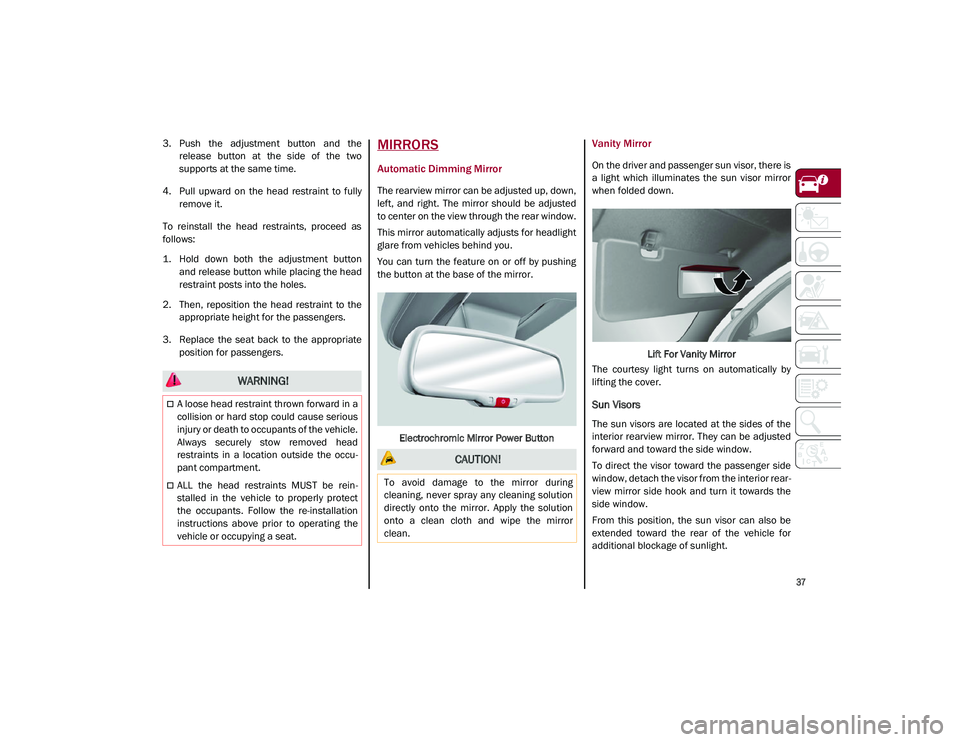
The rearview mirror can be adjusted up, down,
left, and right. The mirror should be adjusted
to center on the view through the rear window.
This mirror automatically adjusts for headlight
glare from vehicles behind you.
You can turn the feature on or off by pushing
the button at the base of the mirror.
Electrochromic Mirror Power Button
Vanity Mirror
On the driver and passenger sun visor, there is
a light which illuminates the sun visor mirror
when folded down. Lift For Vanity Mirror
The courtesy light turns on automatically by
lifting the cover.
Sun Visors
The sun visors are located at the sides of the
interior rearview mirror. They can be adjusted
forward and toward the side window.
To direct the visor toward the passenger side
window, detach the visor from the interior rear -
view mirror side hook and turn it towards the
side window.
From this position, the sun visor can also be
extended toward the rear of the vehicle for
additional blockage of sunlight.
WARNING!
A loose head restraint thrown forward in a
collision or hard stop could cause serious
injury or death to occupants of the vehicle.
Always securely stow removed head
restraints in a location outside the occu -
pant compartment.
ALL the head restraints MUST be rein -
stalled in the vehicle to properly protect
the occupants. Follow the re-installation
instructions above prior to operating the
vehicle or occupying a seat.
CAUTION!
To avoid damage to the mirror during
cleaning, never spray any cleaning solution
directly onto the mirror. Apply the solution
onto a clean cloth and wipe the mirror
clean.
21_GU_OM_EN_USC_t.book Page 37
Page 169 of 280
167
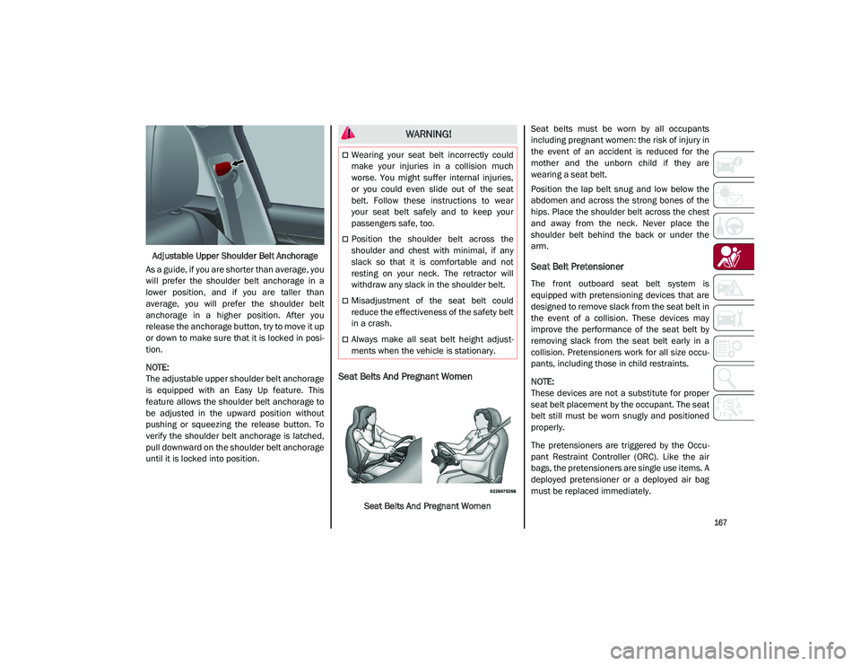
Adjustable Upper Shoulder Belt Anchorage
As a guide, if you are shorter than average, you
will prefer the shoulder belt anchorage in a
lower position, and if you are taller than
average, you will prefer the shoulder belt
anchorage in a higher position. After you
release the anchorage button, try to move it up
or down to make sure that it is locked in posi -
tion.
NOTE:
The adjustable upper shoulder belt anchorage
is equipped with an Easy Up feature. This
feature allows the shoulder belt anchorage to
be adjusted in the upward position without
pushing or squeezing the release button. To
verify the shoulder belt anchorage is latched,
pull downward on the shoulder belt anchorage
until it is locked into position.
Seat Belts And Pregnant Women
Seat Belts And Pregnant Women Seat belts must be worn by all occupants
including pregnant women: the risk of injury in
the event of an accident is reduced for the
mother and the unborn child if they are
wearing a seat belt.
Position the lap belt snug and low below the
abdomen and across the strong bones of the
hips. Place the shoulder belt across the chest
and away from the neck. Never place the
shoulder belt behind the back or under the
arm.
Seat Belt Pretensioner
The front outboard seat belt system is
equipped with pretensioning devices that are
designed to remove slack from the seat belt in
the event of a collision. These devices may
improve the performance of the seat belt by
removing slack from the seat belt early in a
collision. Pretensioners work for all size occu-
pants, including those in child restraints.
NOTE:
These devices are not a substitute for proper
seat belt placement by the occupant. The seat
belt still must be worn snugly and positioned
properly.
The pretensioners are triggered by the Occu
-
pant Restraint Controller (ORC). Like the air
bags, the pretensioners are single use items. A
deployed pretensioner or a deployed air bag
must be replaced immediately.
WARNING!
Wearing your seat belt incorrectly could
make your injuries in a collision much
worse. You might suffer internal injuries,
or you could even slide out of the seat
belt. Follow these instructions to wear
your seat belt safely and to keep your
passengers safe, too.
Position the shoulder belt across the
shoulder and chest with minimal, if any
slack so that it is comfortable and not
resting on your neck. The retractor will
withdraw any slack in the shoulder belt.
Misadjustment of the seat belt could
reduce the effectiveness of the safety belt
in a crash.
Always make all seat belt height adjust -
ments when the vehicle is stationary.
21_GU_OM_EN_USC_t.book Page 167
Page 274 of 280
272
INDEX
Rear Camera ..............................................132
Rear Cross Path .........................................150
Reformulated Gasoline .............................. 260
Refueling Procedure ..................................133
Refueling The Vehicle ................................ 133
Reminder, Seat Belt ...................................164
Remote ControlStarting System........................................ 22
Remote Keyless Entry .................................. 18
Remote Starting Exit Remote Start Mode .......................... 22
Remote Starting System ....................... 22, 86
Replacement Tires ..................................... 244
Reporting Safety Defects ...........................267
Restraints, Child .........................................178
Restraints, Head .......................................... 35
Rims And Tires ...........................................233
Roll Over Warning........................................... 3
S
Safety Checks Inside Vehicle ....................189
Safety Checks Outside Vehicle.................. 190
Safety Defects, Reporting ..........................267
Safety Information, Tire .............................233
Safety Tips ..................................................188
Safety, Exhaust Gas ...................................190
Saving Fuel .................................................142
Scheduled Servicing ..................................208
Scheduled Servicing Program
(2.0L T4 MAir Engine Versions) ................. 209
Scheduled Servicing Program
(2.9L V6 Gasoline Engine Versions) .........212
Seat Belt Reminder ...................................... 75
Seat Belts ..........................................164, 189 Adjustable Shoulder Belt ....................... 166 Adjustable Upper Shoulder
Anchorage .......................................... 166
Adjustable Upper Shoulder Belt Anchorage .......................................... 166
Child Restraints ..................................... 178
Energy Management Feature ............... 168
Front Seat .............................................. 164
Inspection .............................................. 189
Lap/Shoulder Belt Untwisting............... 166
Lap/Shoulder Belts ............................... 164
Pregnant Women ................................... 167
Pretensioners......................................... 167
Rear Seat ............................................... 164
Reminder................................................ 164
Seat Belt Pretensioner .......................... 167 Untwisting Procedure ............................ 166
Seats.......................................................30, 33 Adjustment .................................. 30, 31, 33
Head Restraints ....................................... 35
Heated...................................................... 34
Height Adjustment ................................... 33
Power........................................................ 33
Tilting ........................................................ 33
Security Alarm .............................................. 23
Service Assistance ..................................... 266
Service Contract......................................... 267
Service Manuals ........................................ 268
Servicing Procedures ................................. 219
Shoulder Belts............................................ 164
Signals, Turn .................................44, 78, 190
Snow Chains .............................................. 247
Snow Tires .................................................. 246
Spare Tires ........................................ 244, 245 Speed Control
Accel/Decel .................................. 105, 106
Accel/Decel (ACC Only) ......................... 109
Cancel .................................................... 106Distance Setting (ACC Only).................. 110
Resume.................................................. 106
Set .......................................................... 105
Speed Control (Cruise Control) ................. 104
Starting....................................................... 204 Button .......................................................20Cold Weather ............................................87
Remote .....................................................22
Starting And Operating .............................. 204
Starting Procedures .................................. 204
Starting The Engine ......................................86
Steering ...................................................... 256 Wheel, Heated .......................................... 29
Wheel, Tilt ................................................. 28
Stop/Start System ..................................... 101
Storage Console .....................................................56
Suggestions For Driving ............................ 142
Sun Roof ................................................ 59, 61
Supplemental Restraint System –
Air Bag ........................................................ 170
Suspension ................................................ 256
System, Remote Starting ............................. 22
T
Telescoping Steering Column ...................... 28
Tilt Steering Column .....................................28
Tire And Loading Information Placard ..... 237
Tire Markings ............................................. 234
Tire Safety Information ............................. 233
Tire Service Kit........................................... 198
21_GU_OM_EN_USC_t.book Page 272