2021 ALFA ROMEO STELVIO four wheel drive
[x] Cancel search: four wheel drivePage 14 of 280

12
JUMP STARTING .................................... 201
Remote Battery Connection Posts......202
Jump Starting Procedure.....................203
Bump Starting ..................................204
ENGINE OVERHEATING ......................... 204 MANUAL PARK RELEASE ...................... 205TOWING A DISABLED VEHICLE ............. 205
Four-Wheel Drive (AWD) Models .........206
TOW EYES .............................................. 206
ENHANCED ACCIDENT RESPONSE
SYSTEM (EARS) ..................................... 207EVENT DATA RECORDER (EDR) ............ 207
SERVICING AND MAINTENANCE
SCHEDULED SERVICING ....................... 208
Periodic Checks ...................................208
Heavy Usage Of The Vehicle ...............208
Maintenance Plan (2.0L Engine) ........209
Maintenance Plan (2.9L Engine) ........212
ENGINE COMPARTMENT....................... 214
Checking Levels — 2.0L Engine .......... 214
Checking Levels — 2.9L Engine .......... 215
Engine Oil ............................................. 215
Engine Coolant Fluid............................216
Washer Fluid For Windshield/
Headlights ............................................ 217 Brake Fluid ...........................................217
Automatic Transmission Activation
System Oil ............................................ 217 Useful Advice For Extending The Life Of
Your Battery..........................................217 Battery ..................................................217
Pressure Washing ................................ 218
BATTERY RECHARGING ......................... 218
Important Notes .................................. 218
VEHICLE MAINTENANCE ........................ 219
Engine Oil ............................................. 219
Engine Oil Filter ................................... 220
Engine Air Cleaner Filter ..................... 220
Air Conditioning System
Maintenance........................................ 220 Lubricating Moving Parts Of The
Bodywork ............................................. 220 Windshield Wiper................................. 221
Exhaust System ................................... 222
Cooling System .................................... 223
Braking System.................................... 224
Automatic Transmission ..................... 225
Replacing The Battery ......................... 225
Fuses .................................................... 225
Bulb Replacement ............................... 229
TIRES ...................................................... 233
Tire Safety Information .................... 233
Tires — General Information .............. 239
Spare Tires — If Equipped .................. 244
Wheel And Wheel Trim Care ............ 245
Tire Types ............................................. 246
Tire Chains and Traction Devices ....... 247
Tire Rotation Recommendations........ 247
DEPARTMENT OF TRANSPORTATION
UNIFORM TIRE QUALITY GRADES ......... 248
Treadwear ............................................ 248
Traction Grades ................................... 248
Temperature Grades ........................... 248
STORING THE VEHICLE ......................... 249 BODYWORK ........................................... 249
Protection Against Atmospheric
Agents .................................................. 249 Corrosion Warranty ............................. 250
Preserving The Bodywork .................. 250
INTERIORS ............................................. 251
Seats And Fabric Parts ....................... 251
Leather Seats ...................................... 251
Plastic And Coated Parts .................... 251
Alcantara Parts — If Equipped ............ 251
Genuine Leather Parts........................ 251
Carbon Fiber Parts .............................. 252
TECHNICAL SPECIFICATIONS
VEHICLE IDENTIFICATION
NUMBER (VIN) ....................................... 253
Vehicle Identification Number............ 253
Vehicle Identification Number
(VIN) Plate ............................................ 253
ENGINE .................................................. 254
POWER SUPPLY ..................................... 255 TRANSMISSION ..................................... 255BRAKES.................................................. 255
SUSPENSION ......................................... 256
STEERING .............................................. 256
DIMENSIONS ......................................... 257
Luggage Compartment Volume ......... 259
WEIGHTS ................................................ 259
21_GU_OM_EN_USC_t.book Page 12
Page 77 of 280
75
Vehicles equipped with the Anti-Lock Brake
System (ABS) are also equipped with Elec-
tronic Brake Force Distribution (EBD). In the
event of an EBD failure, the Brake Warning
Light will turn on along with the ABS Light.
Immediate repair to the ABS system is
required.
Operation of the Brake Warning Light can be
checked by turning the ignition switch from the
OFF position to the ON/RUN position. The light
should illuminate for approximately two
seconds. The light should then turn off unless
the parking brake is applied or a brake fault is
detected. If the light does not illuminate, have
the light inspected by an authorized dealer.
The light also will turn on when the parking
brake is applied with the ignition switch in the
ON/RUN position.
NOTE:
This light shows only that the parking brake is
applied. It does not show the degree of brake
application.
Seat Belt Reminder Warning Light
When the ignition is first placed in
the ON/RUN position, if the driver’s
seat belt is unbuckled, a chime will
sound and the light will turn on.
When driving, if the driver or front passenger
seat belt remains unbuckled, the Seat Belt
Reminder Light will flash or remain on contin -
uously and a chime will sound
Ú
page 163.
Electronic Brake Force Distribution (EBD)
Failure
The simultaneous turning on of the
BRAKE (red) and (amber) warning
lights with the engine on indicates
either a failure of the EBD system or
that the system is not available. In this case,
the rear wheels may suddenly lock and the
vehicle may swerve when braking abruptly.
Drive very carefully to the nearest authorized
dealer to have the system inspected immedi -
ately.
Oil Temperature Warning Light
This telltale indicates engine oil
temperature is high.
Stop the vehicle and shut off the engine as
soon as possible. If the problem persists,
contact an authorized dealer.
Amber Warning Lights
Anti-Lock Brake System (ABS) Warning Light
This light monitors the ABS. The light
will turn on when the ignition is
placed in the ON/RUN position and
may stay on for as long as four
seconds.
If the ABS light remains on or turns on while
driving, then the Anti-Lock portion of the brake
system is not functioning and service is
If the warning light does not turn on when
the ignition device is moved to ON or if it
stays on when driving (together with the
message on the display), there might be a
fault in the restraint systems; in this case,
the air bags or pretensioners may not
deploy in the event of an accident or, in a
lower number of cases, they could deploy
erroneously. Before proceeding, contact
an authorized dealer to have the system
checked immediately.
WARNING! (Continued)
WARNING!
The fault of the warning light is signaled by
the turning on of the icon on the instru -
ment panel. In this case, the warning light
may not indicate any faults with the
restraint systems. Before proceeding,
contact an authorized dealer to have the
system checked immediately.
If the warning light does not turn on when
the ignition device is moved to ON or if it
stays on when driving (together with the
message on the display), there might be a
fault in the restraint systems; in this case,
the air bags or pretensioners may not
deploy in the event of an accident or, in a
lower number of cases, they could deploy
erroneously. Before proceeding, contact
an authorized dealer to have the system
checked immediately.
21_GU_OM_EN_USC_t.book Page 75
Page 98 of 280
STARTING AND OPERATING
96
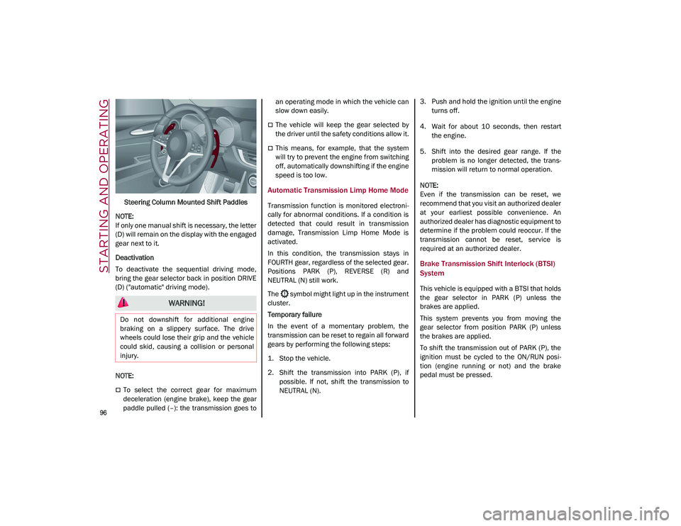
Steering Column Mounted Shift Paddles
NOTE:
If only one manual shift is necessary, the letter
(D) will remain on the display with the engaged
gear next to it.
Deactivation
To deactivate the sequential driving mode,
bring the gear selector back in position DRIVE
(D) ("automatic" driving mode).
NOTE:
To select the correct gear for maximum
deceleration (engine brake), keep the gear
paddle pulled (–): the transmission goes to an operating mode in which the vehicle can
slow down easily.
The vehicle will keep the gear selected by
the driver until the safety conditions allow it.
This means, for example, that the system
will try to prevent the engine from switching
off, automatically downshifting if the engine
speed is too low.
Automatic Transmission Limp Home Mode
Transmission function is monitored electroni
-
cally for abnormal conditions. If a condition is
detected that could result in transmission
damage, Transmission Limp Home Mode is
activated.
In this condition, the transmission stays in
FOURTH gear, regardless of the selected gear.
Positions PARK (P), REVERSE (R) and
NEUTRAL (N) still work.
The symbol might light up in the instrument
cluster.
Temporary failure
In the event of a momentary problem, the
transmission can be reset to regain all forward
gears by performing the following steps:
1. Stop the vehicle.
2. Shift the transmission into PARK (P), if possible. If not, shift the transmission to
NEUTRAL (N). 3. Push and hold the ignition until the engine
turns off.
4. Wait for about 10 seconds, then restart the engine.
5. Shift into the desired gear range. If the problem is no longer detected, the trans -
mission will return to normal operation.
NOTE:
Even if the transmission can be reset, we
recommend that you visit an authorized dealer
at your earliest possible convenience. An
authorized dealer has diagnostic equipment to
determine if the problem could reoccur. If the
transmission cannot be reset, service is
required at an authorized dealer.
Brake Transmission Shift Interlock (BTSI)
System
This vehicle is equipped with a BTSI that holds
the gear selector in PARK (P) unless the
brakes are applied.
This system prevents you from moving the
gear selector from position PARK (P) unless
the brakes are applied.
To shift the transmission out of PARK (P), the
ignition must be cycled to the ON/RUN posi -
tion (engine running or not) and the brake
pedal must be pressed.
WARNING!
Do not downshift for additional engine
braking on a slippery surface. The drive
wheels could lose their grip and the vehicle
could skid, causing a collision or personal
injury.
21_GU_OM_EN_USC_t.book Page 96
Page 141 of 280
139
(Continued)
Consider the following items when computing
the weight on the rear axle of the vehicle:
The tongue weight of the trailer.
The weight of any other type of cargo or
equipment put in or on your vehicle.
The weight of the driver and all passengers.
NOTE:
Remember that everything put into or on the
trailer adds to the load on your vehicle. Also,
additional factory-installed options or
dealer-installed options must be considered
as part of the total load on your vehicle. Refer
to the “Tire And Loading Information” placard
for the maximum combined weight of occu -
pants and cargo for your vehicle.
Towing Requirements
To promote proper break-in of your new
vehicle drivetrain components, the following
guidelines are recommended:
Towing Requirements — Tires
Do not attempt to tow a trailer while using a
compact spare tire.
Do not drive more than 50 mph (80 km/h)
when towing while using a full size spare
tire.
Proper tire inflation pressures are essential
to the safe and satisfactory operation of
your vehicle.
Check the trailer tires for proper tire infla -
tion pressures before trailer usage.
Check for signs of tire wear or visible tire
damage before towing a trailer.
Replacing tires with a higher load carrying
capacity will not increase the vehicle's
GVWR and GAWR limits.
For proper tire inflation procedures
Ú
page 233.
WARNING!
Improper towing can lead to a collision.
Follow these guidelines to make your trailer
towing as safe as possible:
Make certain that the load is secured in
the trailer and that it will not shift during
travel. When trailering cargo that is not
fully secured, dynamic load shifts can
occur that may be difficult for the driver to
control. You could lose control of your
vehicle and have a collision.
When hauling cargo, or towing a trailer, do
not overload your vehicle or trailer. Over -
loading can cause a loss of control, poor
performance, or damage to brakes, axle,
engine, transmission, steering, suspen -
sion, chassis structure, or tires.
Safety chains must always be used
between your vehicle and trailer. Always
connect the chains to the frame or hook
retainers of the vehicle hitch. Cross the
chains under the trailer tongue and allow
enough slack for turning corners.
Vehicles with trailers should not be parked
on a grade. When parking, apply the
parking brake on the tow vehicle. Put the
tow vehicle transmission in PARK. Always
block or "chock" the trailer wheels.
GCWR must not be exceeded.
Total weight must be distributed between
the tow vehicle and the trailer such that
the following four ratings are not
exceeded:
• GVWR
• GTW
• GAWR
• Tongue weight rating for the trailer
hitch utilized.
WARNING! (Continued) CAUTION!
Do not tow a trailer at all during the first
500 miles (805 km) the new vehicle is
driven. The engine, axle or other parts
could be damaged.
Then, during the first 500 miles (805 km)
that a trailer is towed, do not drive over
50 mph (80 km/h) and do not make
starts at full throttle. This helps the engine
and other parts of the vehicle wear in at
the heavier loads.
21_GU_OM_EN_USC_t.book Page 139
Page 145 of 280
143
Traffic And Road Conditions
High fuel consumption is caused by heavy
traffic, for instance when traveling in traffic
with frequent use of low gears or in cities with
many traffic lights. Winding mountain roads
and rough road surfaces also adversely affect
consumption.
Stops In Traffic
During prolonged stops (e.g. railway cross-
ings), turn off the engine.
Performance — Quadrifoglio
This vehicle is equipped with an engine
capable of delivering exceptionally fast accel -
eration and speed:
Peak power: 505 HP at 6,500 RPM.
Peak torque: 443 ft-lbs at 2,500–5,000 RPM.
Top speed: 176 mph (283 km/h).
Acceleration from 0 to 60 mph (0 to 100 km/h):
3.6 seconds.
For safe driving, it is essential, particularly
during the first days of use, to get to know the
car by driving carefully and gradually discov -
ering its performance.
Brakes
The car braking system may be available with
four carbon-ceramic material brake discs, one
on each wheel. In order to guarantee the maximum braking
capacity for the first use, Alfa Romeo performs
a "run-in" procedure for discs and pads directly
at the factory.
The use of carbon-ceramic material brake
discs guarantees braking features (better
deceleration/pedal load ratio, braking
distances, fading resistance) proportional to
the dynamic features of the car in addition to
considerably decreasing the unsprung compo
-
nent weight.
The materials used and the structural features
of the system could generate unusual noises
which have absolutely no adverse effect on
correct operation and reliability of the braking
system.
Greater pressure may need to be applied to
the brake pedal the first time to keep the same
braking capacities in presence of condensa -
tion or salt on the braking surfaces, for
example after washing or if the car is not used
for a long time.
NOTE:
Given the high technological level of this
system, any servicing on it must be performed
by an authorized dealer which exclusively has
the skills needed for the repair and mainte -
nance operations. In case of intensive, high-performance use of
the car, have the efficiency of the
carbon-ceramic material braking system
inspected as shown on the Maintenance Plan
at an authorized dealer.
Driving On Race Tracks
Before driving on a track using a racing style, it
is necessary to:
Attend a race track driving course.
Check the liquid levels in the engine
compartment
Ú
page 208.
Have the car inspected at an authorized
dealer.
Remember that the car was not designed to be
driven exclusively on the race track and that
this use increases stress and component
wear.
NOTE:
Quadrifoglio front brakes are equipped with
Non-Asbestos Organic (NAO) type pads. These
pads are NOT suitable for high thermal loads
(for example track use). If you want to use
vehicle on a track it is recommended to use
the optional CCM Brakes (Carbon Ceramic
Brake disc).
21_GU_OM_EN_USC_t.book Page 143
Page 164 of 280
SAFETY
162
will turn off only after the tires are inflated to the
vehicle’s recommended cold placard pressure
value.Insufficient Tire Pressure Indication
If an insufficient pressure value is detected on
one or more tires, the warning light in the
instrument cluster will display alongside the
dedicated messages, the system will highlight
the tire or tires with insufficient pressure
graphically, and an acoustic signal will be
emitted.
In this case, stop the vehicle, check the infla
-
tion pressure of each tire, and inflate the
necessary tire or tires to the correct cold infla -
tion pressure value, shown on the display or in
the dedicated TPMS menu.
TPMS Temporarily Disabled:
TPMS Check Message
When a system fault is detected, the TPMS
Warning Light will flash on and off for 75 seconds,
and then remain on solid. The system fault will
also sound a chime. If the ignition is cycled, this
sequence will repeat, provided that the system
fault still exists. The TPMS Warning Light will turn
off when the fault condition no longer exists. A
system fault can occur due to any of the
following:
Jamming due to electronic devices or
driving next to facilities emitting the same
radio frequencies as the TPMS sensors.
Installing some form of aftermarket window
tinting that affects radio wave signals.
Packed snow or ice around the wheels or
wheel housings.
Using tire chains on the vehicle.
Using wheels/tires not equipped with TPMS
sensors.
After the punctured tire has been repaired
with the original tire sealant contained in the
Tire Kit, the previous condition must be
restored so that the warning light is off
during normal driving.
TPMS Deactivation
The TPMS can be deactivated by replacing all
four wheel and tire assemblies (road tires)
with wheel and tire assemblies that do not
have TPMS sensors, such as when installing
winter wheel and tire assemblies on your
vehicle.
To deactivate the TPMS, first replace all four
wheel and tire assemblies (road tires) with tires
not equipped with Tire Pressure Monitoring
System (TPMS) sensors. Then, drive the vehicle
for 20 minutes above 15 mph (24 km/h). The
TPMS will chime, the TPMS Warning Light will
flash on and off for 75 seconds and then
remain on. The instrument cluster will display
the “SERVICE TPM SYSTEM” message and then
display dashes (--) in place of the pressure
values.
Beginning with the next ignition switch cycle,
the TPMS will no longer chime or display the
“SERVICE TPM SYSTEM” message in the
instrument cluster. Instead, dashes (--) will
remain in place of the pressure values.
CAUTION!
The TPMS has been optimized for the orig -
inal equipment tires and wheels. TPMS
pressures and warning have been estab -
lished for the tire size equipped on your
vehicle. Undesirable system operation or
sensor damage may result when using
replacement equipment that is not of the
same size, type, and/or style. The TPMS
sensor is not designed for use on after -
market wheels and may contribute to a
poor overall system performance or
sensor damage. Customers are encour -
aged to use OEM wheels to assure proper
TPMS feature operation.
Using aftermarket tire sealants may cause
the Tire Pressure Monitoring System
(TPMS) sensor to become inoperable.
After using an aftermarket tire sealant it is
recommended that you take your vehicle
to an authorized dealer to have your
sensor function checked.
After inspecting or adjusting the tire pres -
sure always reinstall the valve stem cap.
This will prevent moisture and dirt from
entering the valve stem, which could
damage the TPMS sensor.
21_GU_OM_EN_USC_t.book Page 162
Page 165 of 280
163
To reactivate the TPMS, replace all four wheel
and tire assemblies (road tires) with tires
equipped with TPMS sensors. Then, drive the
vehicle for up to 20 minutes above 15 mph
(24 km/h). The TPMS will chime, the TPMS
Warning Light will flash on and off for 75
seconds and then turn off. The instrument
cluster will display the “SERVICE TPM
SYSTEM” message and then display pressure
values in place of the dashes. On the next igni-
tion switch cycle the “SERVICE TPM SYSTEM”
message will no longer be displayed, as long
as no system fault exists.
NOTE:
The TPMS is not intended to replace normal
tire care and maintenance, or to provide
warning of a tire failure or condition.
The TPMS should not be used as a tire pres -
sure gauge while adjusting your tire pres -
sure.
Driving on a significantly underinflated tire
will cause the tire to overheat, and can lead
to tire failure. Underinflation also reduces
fuel efficiency and tire tread life, and may
affect the vehicle’s handling and stopping
ability.
The TPMS is not a substitute for proper tire
maintenance, and it is the driver’s responsi -
bility to maintain correct tire pressure using
an accurate tire pressure gauge, even if underinflation has not reached the level to
trigger illumination of the TPMS Warning
Light.
Seasonal temperature changes will affect
tire pressure, and the TPMS will monitor the
actual tire pressure in the tire
Ú
page 268.
OCCUPANT RESTRAINT
SYSTEMS
Some of the most important safety features in
your vehicle are the restraint systems:
Occupant Restraint Systems Features
Seat Belt Systems
Supplemental Restraint Systems (SRS) Air
Bags
Child Restraints
Some of the safety features described in this
section may be standard equipment on some
models, or may be optional equipment on
others. If you are not sure, ask an authorized
dealer.
Important Safety Precautions
Please pay close attention to the information
in this section. It tells you how to use your
restraint system properly, to keep you and
your passengers as safe as possible. Here are some simple steps you can take to
minimize the risk of harm from a deploying air
bag:
1. Children 12 years old and under should
always ride buckled up in the rear seat of
a vehicle with a rear seat.
2. A child who is not big enough to wear the vehicle seat belt properly must be secured
in the appropriate child restraint or
belt-positioning booster seat in a rear
seating position
Ú
page 178.
3. If a child from 2 to 12 years old (not in a rear-facing child restraint) must ride in the
front passenger seat, move the seat as far
back as possible and use the proper child
restraint
Ú
page 178.
4. Never allow children to slide the shoulder belt behind them or under their arm.
5. You should read the instructions provided with your child restraint to make sure that
you are using it properly.
6. All occupants should always wear their lap and shoulder belts properly.
7. The driver and front passenger seats should be moved back as far as practical
to allow the front air bags room to inflate.
8. Do not lean against the door or window. If your vehicle has side air bags, and deploy -
ment occurs, the side air bags will inflate
21_GU_OM_EN_USC_t.book Page 163
Page 171 of 280
169
Supplemental Restraint Systems (SRS)
Some of the safety features described in this
section may be standard equipment on some
models, or may be optional equipment on
others. If you are not sure, ask an authorized
dealer.
The air bag system must be ready to protect
you in a collision. The Occupant Restraint
Controller (ORC) monitors the internal circuits
and interconnecting wiring associated with the
electrical Air Bag System Components. Your
vehicle may be equipped with the following Air
Bag System Components:
Air Bag System Components
Occupant Restraint Controller (ORC)
Air Bag Warning Light
Steering Wheel and Column
Instrument Panel
Knee Impact Bolsters
Driver and Front Passenger Air Bags
Seat Belt Buckle Switch
Supplemental Side Air Bags
Supplemental Knee Air Bags
Front and Side Impact Sensors
Seat Belt Pretensioners
Seat Track Position Sensors
Air Bag Warning Light
The Occupant Restraint Controller
(ORC) monitors the readiness of the
electronic parts of the air bag system
whenever the ignition switch is in the
START or ON/RUN position. If the ignition
switch is in the OFF position or in the ACC posi -
tion, the air bag system is not on and the air
bags will not inflate.
The ORC contains a backup power supply
system that may deploy the air bag system
even if the battery loses power or it becomes
disconnected prior to deployment.
The ORC turns on the Air Bag Warning Light in
the instrument panel for approximately four to
eight seconds for a self-check when the igni -
tion switch is first in the ON/RUN position.
After the self-check, the Air Bag Warning Light
will turn off. If the ORC detects a malfunction
in any part of the system, it turns on the Air
Bag Warning Light, either momentarily or continuously. A single chime will sound to alert
you if the light comes on again after initial
startup.
The ORC also includes diagnostics that will illu
-
minate the instrument panel Air Bag Warning
Light if a malfunction is detected that could
affect the air bag system. The diagnostics also
record the nature of the malfunction. While
the air bag system is designed to be mainte -
nance free, if any of the following occurs, have
an authorized dealer service the air bag
system immediately.The Air Bag Warning Light does not come on
during the four to eight seconds when the
ignition switch is first in the ON/RUN posi -
tion.
The Air Bag Warning Light remains on after
the four to eight-second interval.
The Air Bag Warning Light comes on inter-
mittently or remains on while driving.
NOTE:
If the speedometer, tachometer, or any engine
related gauges are not working, the Occupant
Restraint Controller (ORC) may also be
disabled. In this condition the air bags may not
be ready to inflate for your protection. Have an
authorized dealer service the air bag system
immediately.
Do not use the Automatic Locking Mode to
restrain occupants who are wearing the
seat belt or children who are using booster
seats. The locked mode is only used to
install rear-facing or forward-facing child
restraints that have a harness for
restraining the child.
WARNING! (Continued)
21_GU_OM_EN_USC_t.book Page 169