2021 ALFA ROMEO STELVIO brake fluid
[x] Cancel search: brake fluidPage 14 of 280

12
JUMP STARTING .................................... 201
Remote Battery Connection Posts......202
Jump Starting Procedure.....................203
Bump Starting ..................................204
ENGINE OVERHEATING ......................... 204 MANUAL PARK RELEASE ...................... 205TOWING A DISABLED VEHICLE ............. 205
Four-Wheel Drive (AWD) Models .........206
TOW EYES .............................................. 206
ENHANCED ACCIDENT RESPONSE
SYSTEM (EARS) ..................................... 207EVENT DATA RECORDER (EDR) ............ 207
SERVICING AND MAINTENANCE
SCHEDULED SERVICING ....................... 208
Periodic Checks ...................................208
Heavy Usage Of The Vehicle ...............208
Maintenance Plan (2.0L Engine) ........209
Maintenance Plan (2.9L Engine) ........212
ENGINE COMPARTMENT....................... 214
Checking Levels — 2.0L Engine .......... 214
Checking Levels — 2.9L Engine .......... 215
Engine Oil ............................................. 215
Engine Coolant Fluid............................216
Washer Fluid For Windshield/
Headlights ............................................ 217 Brake Fluid ...........................................217
Automatic Transmission Activation
System Oil ............................................ 217 Useful Advice For Extending The Life Of
Your Battery..........................................217 Battery ..................................................217
Pressure Washing ................................ 218
BATTERY RECHARGING ......................... 218
Important Notes .................................. 218
VEHICLE MAINTENANCE ........................ 219
Engine Oil ............................................. 219
Engine Oil Filter ................................... 220
Engine Air Cleaner Filter ..................... 220
Air Conditioning System
Maintenance........................................ 220 Lubricating Moving Parts Of The
Bodywork ............................................. 220 Windshield Wiper................................. 221
Exhaust System ................................... 222
Cooling System .................................... 223
Braking System.................................... 224
Automatic Transmission ..................... 225
Replacing The Battery ......................... 225
Fuses .................................................... 225
Bulb Replacement ............................... 229
TIRES ...................................................... 233
Tire Safety Information .................... 233
Tires — General Information .............. 239
Spare Tires — If Equipped .................. 244
Wheel And Wheel Trim Care ............ 245
Tire Types ............................................. 246
Tire Chains and Traction Devices ....... 247
Tire Rotation Recommendations........ 247
DEPARTMENT OF TRANSPORTATION
UNIFORM TIRE QUALITY GRADES ......... 248
Treadwear ............................................ 248
Traction Grades ................................... 248
Temperature Grades ........................... 248
STORING THE VEHICLE ......................... 249 BODYWORK ........................................... 249
Protection Against Atmospheric
Agents .................................................. 249 Corrosion Warranty ............................. 250
Preserving The Bodywork .................. 250
INTERIORS ............................................. 251
Seats And Fabric Parts ....................... 251
Leather Seats ...................................... 251
Plastic And Coated Parts .................... 251
Alcantara Parts — If Equipped ............ 251
Genuine Leather Parts........................ 251
Carbon Fiber Parts .............................. 252
TECHNICAL SPECIFICATIONS
VEHICLE IDENTIFICATION
NUMBER (VIN) ....................................... 253
Vehicle Identification Number............ 253
Vehicle Identification Number
(VIN) Plate ............................................ 253
ENGINE .................................................. 254
POWER SUPPLY ..................................... 255 TRANSMISSION ..................................... 255BRAKES.................................................. 255
SUSPENSION ......................................... 256
STEERING .............................................. 256
DIMENSIONS ......................................... 257
Luggage Compartment Volume ......... 259
WEIGHTS ................................................ 259
21_GU_OM_EN_USC_t.book Page 12
Page 18 of 280
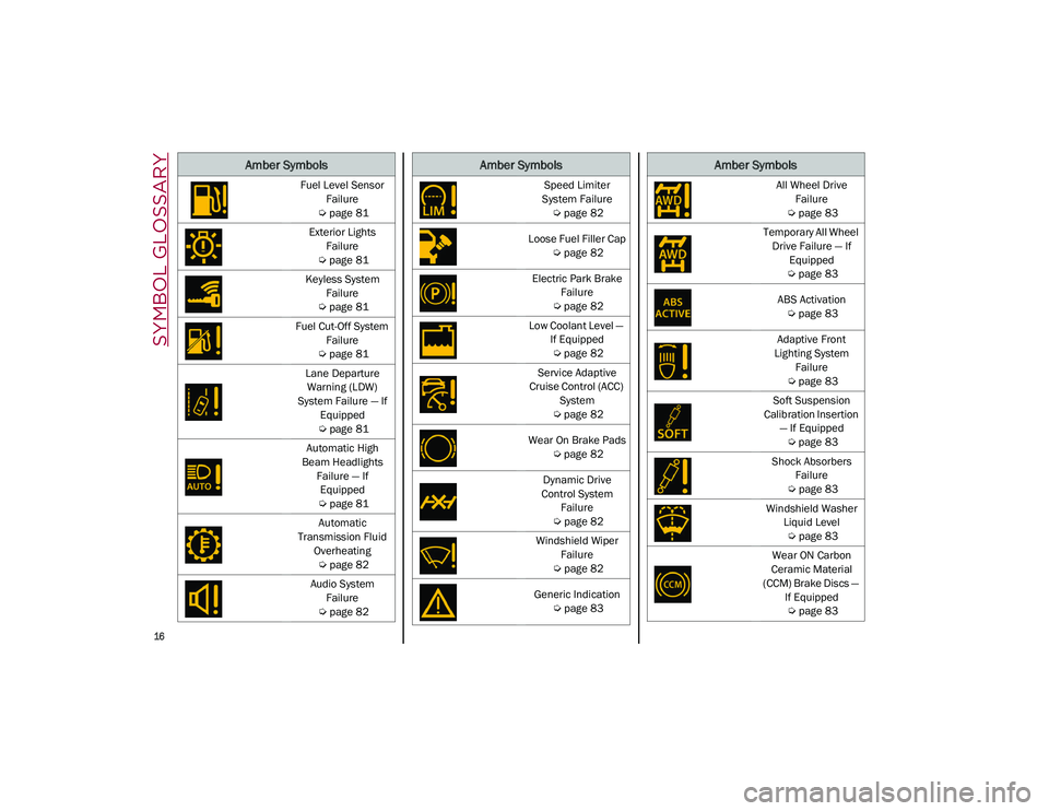
SYMBOL GLOSSARY
16
Fuel Level Sensor
Failure
Ú
page 81
Exterior Lights Failure
Ú
page 81
Keyless System Failure
Ú
page 81
Fuel Cut-Off System Failure
Ú
page 81
Lane Departure Warning (LDW)
System Failure — If Equipped
Ú
page 81
Automatic High
Beam Headlights Failure — If Equipped
Ú
page 81
Automatic
Transmission Fluid Overheating
Ú
page 82
Audio System Failure
Ú
page 82
Amber Symbols
Speed Limiter
System Failure
Ú
page 82
Loose Fuel Filler Cap
Ú
page 82
Electric Park Brake Failure
Ú
page 82
Low Coolant Level — If Equipped
Ú
page 82
Service Adaptive
Cruise Control (ACC) System
Ú
page 82
Wear On Brake Pads
Ú
page 82
Dynamic Drive
Control System Failure
Ú
page 82
Windshield Wiper Failure
Ú
page 82
Generic Indication
Ú
page 83
Amber Symbols
All Wheel Drive
Failure
Ú
page 83
Temporary All Wheel Drive Failure — If Equipped
Ú
page 83
ABS Activation
Ú
page 83
Adaptive Front
Lighting System Failure
Ú
page 83
Soft Suspension
Calibration Insertion — If Equipped
Ú
page 83
Shock Absorbers Failure
Ú
page 83
Windshield Washer Liquid Level
Ú
page 83
Wear ON Carbon
Ceramic Material
(CCM) Brake Discs — If Equipped
Ú
page 83
Amber Symbols
21_GU_OM_EN_USC_t.book Page 16
Page 76 of 280
GETTING TO KNOW YOUR INSTRUMENT PANEL
74
(Continued)
To access and the change the setting, turn and
push the Rotary Pad or press the desired
setting on the touchscreen.
WARNING LIGHTS AND
MESSAGES ON THE
INSTRUMENT PANEL
The following pages consist of warning lights
and messages.
NOTE:
The warning light turns on together with a
dedicated message and/or chime when
applicable. These indications are precau-
tionary and as such must not be considered
as exhaustive and/or alternative to the
information contained in the Owner’s
Manual, which you are advised to read care -
fully in all cases. Always refer to the informa -
tion in this section in the event of a failure
indication.
The failure indicators appearing on the
display are divided into two categories: very
serious and less serious faults. Serious
faults are indicated by a repeated and
prolonged warning cycle. Less serious faults
are indicated by a warning cycle with a
shorter duration. You can stop the warning
cycle in both cases by pushing the button
located on the windshield wiper stalk. The
instrument panel warning light will stay on
until the cause of the failure is eliminated.
Red Warning Lights
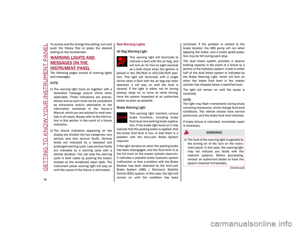
Air Bag Warning Light
This warning light will illuminate to
indicate a fault with the air bag, and
will turn on for four to eight seconds
as a bulb check when the ignition is
placed in the ON/RUN or ACC/ON/RUN posi -
tion. This light will illuminate with a single
chime when a fault with the air bag has been
detected, it will stay on until the fault is
cleared. If the light is either not on during
startup, stays on, or turns on while driving,
have the system inspected at an authorized
dealer as soon as possible.
Brake Warning Light
This warning light monitors various
brake functions, including brake
fluid level and parking brake applica -
tion. If the brake light turns on it may
indicate that the parking brake is applied, that
the brake fluid level is low, or that there is a
problem with the Anti-Lock Brake System
reservoir.
If the light remains on when the parking brake
has been disengaged, and the fluid level is at
the full mark on the master cylinder reservoir,
it indicates a possible brake hydraulic system
malfunction or that a problem with the Brake
Booster has been detected by the Anti-Lock
Brake System (ABS) / Electronic Stability
Control (ESC) system. In this case, the light will
remain on until the condition has been corrected. If the problem is related to the
brake booster, the ABS pump will run when
applying the brake, and a brake pedal pulsa
-
tion may be felt during each stop.
The dual brake system provides a reserve
braking capacity in the event of a failure to a
portion of the hydraulic system. A leak in either
half of the dual brake system is indicated by
the Brake Warning Light, which will turn on
when the brake fluid level in the master
cylinder has dropped below a specified level.
The light will remain on until the cause is
corrected.
NOTE:
The light may flash momentarily during sharp
cornering maneuvers, which change fluid level
conditions. The vehicle should have service
performed, and the brake fluid level checked.
If brake failure is indicated, immediate repair
is necessary.
WARNING!
The fault of the warning light is signaled by
the turning on of the icon on the instru -
ment panel. In this case, the warning light
may not indicate any faults with the
restraint systems. Before proceeding,
contact an authorized dealer to have the
system checked immediately.
21_GU_OM_EN_USC_t.book Page 74
Page 84 of 280

GETTING TO KNOW YOUR INSTRUMENT PANEL
82
Automatic Transmission Fluid Overheating
The telltale will illuminate in the case
of transmission overheating, after a
particularly demanding use. In this
case an engine performance limita-
tion is carried out.
Wait for the telltale to turn off with the engine
off or idling.
Audio System Failure
The telltale will illuminate to report a
failure of the audio system.
Contact an authorized dealer as soon as
possible to have the failure eliminated.
Speed Limiter System Failure
While driving, the telltale will illumi -
nate to signal a Speed Limiter
system failure.
Contact an authorized dealer as soon as
possible to have the failure eliminated.
Loose Fuel Filler Cap
Lights up if the fuel tank cap is open
or not properly closed.
Tighten the cap properly.
Electric Park Brake Failure
The telltale will illuminate and a
message will display to signal a
failure in the electric park brake
system.
This failure may partially or completely block
the vehicle because the park brake could
remain activated even if automatically or
manually disengaged using the relevant
controls. In these circumstances, you can
disengage the park brake following the emer -
gency disengagement procedure
Ú
page 90.
If you are still able to drive the vehicle (park
brake is not engaged), drive to the nearest
authorized dealer and remember, when
executing any maneuvers/commands, that
the electric park brake is not operational.
Low Coolant Level — If Equipped
This telltale will illuminate to indicate
that the vehicle coolant level is low.
Service Adaptive Cruise Control (ACC)
System
This light will illuminate when the
ACC is not operating and needs
service.
Contact an authorized dealer to have the
system checked.
Wear On Brake Pads
This light will illuminate when the
brake pads have reached their wear
limit.
Contact an authorized dealer as soon as
possible.
NOTE:
Always use genuine parts or similar because
the Integrated Brake System (IBS) system
could detect anomalies.
Dynamic Drive Control System Failure
The telltale will illuminate to signal a
failure in the dynamic drive control
system.
Windshield Wiper Failure
Signals a windshield wiper failure.
Contact an authorized dealer.
WARNING!
If a failure is present with sharp braking,
the rear wheels may lock and the vehicle
may swerve.
21_GU_OM_EN_USC_t.book Page 82
Page 85 of 280
83
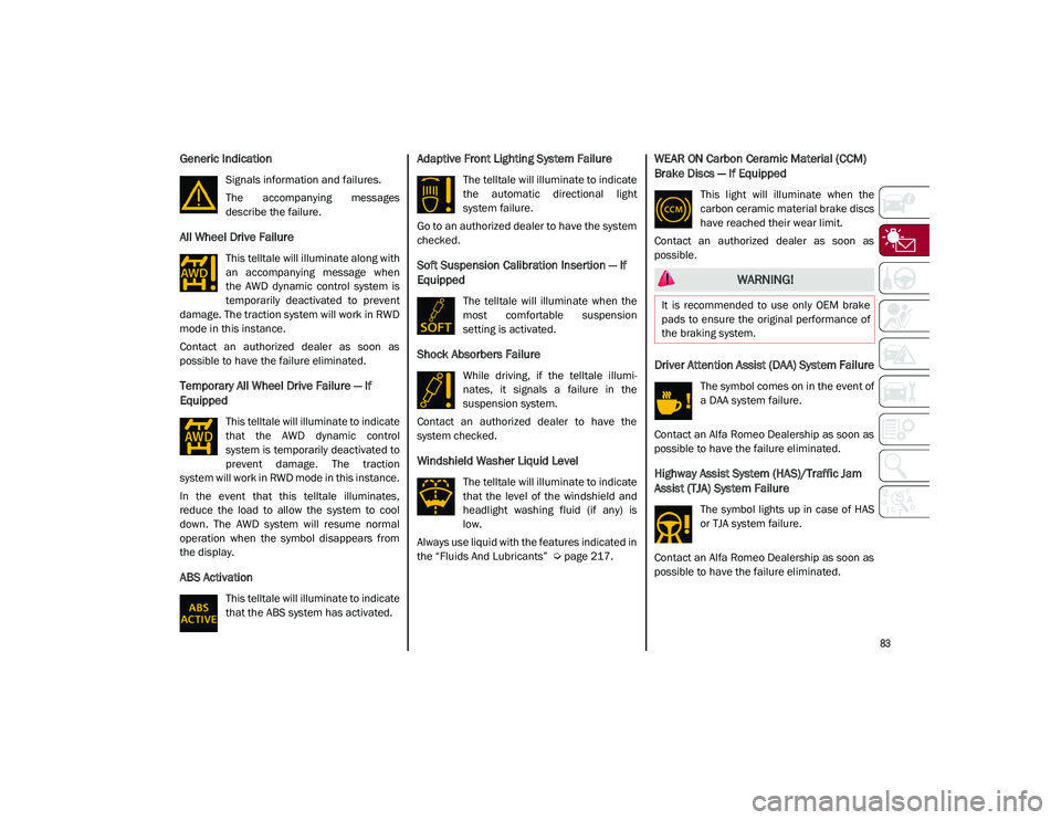
Generic Indication
Signals information and failures.
The accompanying messages
describe the failure.
All Wheel Drive Failure
This telltale will illuminate along with
an accompanying message when
the AWD dynamic control system is
temporarily deactivated to prevent
damage. The traction system will work in RWD
mode in this instance.
Contact an authorized dealer as soon as
possible to have the failure eliminated.
Temporary All Wheel Drive Failure — If
Equipped
This telltale will illuminate to indicate
that the AWD dynamic control
system is temporarily deactivated to
prevent damage. The traction
system will work in RWD mode in this instance.
In the event that this telltale illuminates,
reduce the load to allow the system to cool
down. The AWD system will resume normal
operation when the symbol disappears from
the display.
ABS Activation
This telltale will illuminate to indicate
that the ABS system has activated.
Adaptive Front Lighting System Failure
The telltale will illuminate to indicate
the automatic directional light
system failure.
Go to an authorized dealer to have the system
checked.
Soft Suspension Calibration Insertion — If
Equipped
The telltale will illuminate when the
most comfortable suspension
setting is activated.
Shock Absorbers Failure
While driving, if the telltale illumi -
nates, it signals a failure in the
suspension system.
Contact an authorized dealer to have the
system checked.
Windshield Washer Liquid Level
The telltale will illuminate to indicate
that the level of the windshield and
headlight washing fluid (if any) is
low.
Always use liquid with the features indicated in
the “Fluids And Lubricants”
Ú
page 217.
WEAR ON Carbon Ceramic Material (CCM)
Brake Discs — If Equipped
This light will illuminate when the
carbon ceramic material brake discs
have reached their wear limit.
Contact an authorized dealer as soon as
possible.
Driver Attention Assist (DAA) System Failure
The symbol comes on in the event of
a DAA system failure.
Contact an Alfa Romeo Dealership as soon as
possible to have the failure eliminated.
Highway Assist System (HAS)/Traffic Jam
Assist (TJA) System Failure
The symbol lights up in case of HAS
or TJA system failure.
Contact an Alfa Romeo Dealership as soon as
possible to have the failure eliminated.
WARNING!
It is recommended to use only OEM brake
pads to ensure the original performance of
the braking system.
21_GU_OM_EN_USC_t.book Page 83
Page 100 of 280
STARTING AND OPERATING
98
ALFA DNA SELECTOR
Alfa DNA System
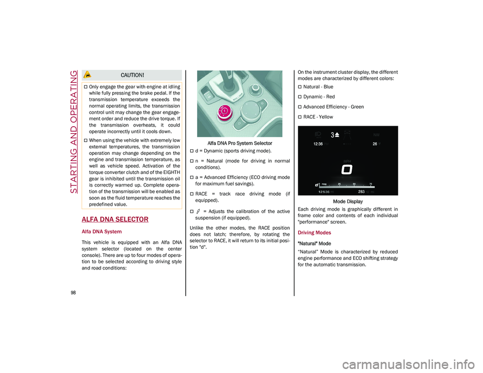
This vehicle is equipped with an Alfa DNA
system selector (located on the center
console). There are up to four modes of opera-
tion to be selected according to driving style
and road conditions: Alfa DNA Pro System Selector
d = Dynamic (sports driving mode).
n = Natural (mode for driving in normal
conditions).
a = Advanced Efficiency (ECO driving mode
for maximum fuel savings).
RACE = track race driving mode (if
equipped).
= Adjusts the calibration of the active
suspension (if equipped).
Unlike the other modes, the RACE position
does not latch; therefore, by rotating the
selector to RACE, it will return to its initial posi -
tion "d". On the instrument cluster display, the different
modes are characterized by different colors:
Natural - Blue
Dynamic - Red
Advanced Efficiency - Green
RACE - Yellow
Mode Display
Each driving mode is graphically different in
frame color and contents of each individual
"performance" screen.
Driving Modes
"Natural" Mode
“Natural” Mode is characterized by reduced
engine performance and ECO shifting strategy
for the automatic transmission.
CAUTION!
Only engage the gear with engine at idling
while fully pressing the brake pedal. If the
transmission temperature exceeds the
normal operating limits, the transmission
control unit may change the gear engage -
ment order and reduce the drive torque. If
the transmission overheats, it could
operate incorrectly until it cools down.
When using the vehicle with extremely low
external temperatures, the transmission
operation may change depending on the
engine and transmission temperature, as
well as vehicle speed. Activation of the
torque converter clutch and of the EIGHTH
gear is inhibited until the transmission oil
is correctly warmed up. Complete opera -
tion of the transmission will be enabled as
soon as the fluid temperature reaches the
predefined value.
21_GU_OM_EN_USC_t.book Page 98
Page 102 of 280
STARTING AND OPERATING
100
ESC and ASR systems: intervention thresholds
aimed at ensuring maximum safety in low-grip
driving conditions. It is advisable to select
“Advanced Efficiency” mode in the presence
of low-grip road surfaces.
Engine and transmission: standard response.
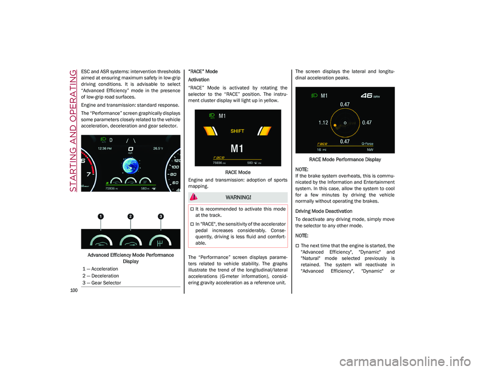
The “Performance” screen graphically displays
some parameters closely related to the vehicle
acceleration, deceleration and gear selector.Advanced Efficiency Mode Performance Display “RACE” Mode
Activation
“RACE” Mode is activated by rotating the
selector to the “RACE” position. The instru-
ment cluster display will light up in yellow.
RACE Mode
Engine and transmission: adoption of sports
mapping.
The “Performance” screen displays parame -
ters related to vehicle stability. The graphs
illustrate the trend of the longitudinal/lateral
accelerations (G-meter information), consid -
ering gravity acceleration as a reference unit. The screen displays the lateral and longitu
-
dinal acceleration peaks.
RACE Mode Performance Display
NOTE:
If the brake system overheats, this is commu -
nicated by the Information and Entertainment
system. In this case, allow the system to cool
for a few minutes by driving the vehicle
normally without operating the brakes.
Driving Mode Deactivation
To deactivate any driving mode, simply move
the selector to any other mode.
NOTE:
The next time that the engine is started, the
"Advanced Efficiency", "Dynamic" and
"Natural" mode selected previously is
retained. The system will reactivate in
"Advanced Efficiency", "Dynamic" or
1 — Acceleration
2 — Deceleration
3 — Gear Selector
WARNING!
It is recommended to activate this mode
at the track.
In "RACE", the sensitivity of the accelerator
pedal increases considerably. Conse
-
quently, driving is less fluid and comfort -
able.
21_GU_OM_EN_USC_t.book Page 100
Page 138 of 280
STARTING AND OPERATING
136
Gross Vehicle Weight Rating (GVWR)
The GVWR is the total permissible weight of
your vehicle including driver, passengers,
vehicle, options and cargo. The label also
specifies maximum capacities of front and
rear axle systems (GAWR). Total load must be
limited so GVWR and front and rear GAWR are
not exceeded.
Payload
The payload of a vehicle is defined as the
allowable load weight a truck can carry,
including the weight of the driver, all passen-
gers, options and cargo.
Gross Axle Weight Rating (GAWR)
The GAWR is the maximum permissible load
on the front and rear axles. The load must be
distributed in the cargo area so that the GAWR
of each axle is not exceeded.
Each axle GAWR is determined by the compo -
nents in the system with the lowest load
carrying capacity (axle, springs, tires or
wheels). Heavier axles or suspension compo -
nents sometimes specified by purchasers for
increased durability do not necessarily
increase the vehicle's GVWR.
Tire Size
The tire size on the Vehicle Certification Label
represents the actual tire size on your vehicle.
Replacement tires must be equal to the load
capacity of this tire size.
Rim Size
This is the rim size that is appropriate for the
tire size listed.
Inflation Pressure
This is the cold tire inflation pressure for your
vehicle for all loading conditions up to full
GAWR.
Curb Weight
The curb weight of a vehicle is defined as the
total weight of the vehicle with all fluids,
including vehicle fuel, at full capacity condi -
tions, and with no occupants or cargo loaded
into the vehicle. The front and rear curb weight
values are determined by weighing your
vehicle on a commercial scale before any
occupants or cargo are added.
Loading
The actual total weight and the weight of the
front and rear of your vehicle at the ground can
best be determined by weighing it when it is
loaded and ready for operation.
The entire vehicle should first be weighed on a
commercial scale to ensure that the GVWR
has not been exceeded. The weight on the
front and rear of the vehicle should then be
determined separately to be sure that the load
is properly distributed over the front and rear
axle. Weighing the vehicle may show that the
GAWR of either the front or rear axles has
been exceeded but the total load is within the specified GVWR. If so, weight must be shifted
from front to rear or rear to front as appro
-
priate until the specified weight limitations are
met. Store the heavier items down low and be
sure that the weight is distributed equally.
Stow all loose items securely before driving.
Improper weight distributions can have an
adverse effect on the way your vehicle steers
and handles and the way the brakes operate.
TRAILER TOWING
In this section you will find safety tips and
information on limits to the type of towing you
can reasonably do with your vehicle. Before
towing a trailer, carefully review this informa -
tion to tow your load as efficiently and safely
as possible.
To maintain the New Vehicle Limited Warranty
coverage, follow the requirements and recom -
mendations in this manual concerning vehi -
cles used for trailer towing.
CAUTION!
Do not load your vehicle any heavier than
the GVWR or the maximum front and rear
GAWR. If you do, parts on your vehicle can
break, or it can change the way your vehicle
handles. This could cause you to lose
control. Also overloading can shorten the
life of your vehicle.
21_GU_OM_EN_USC_t.book Page 136