2021 ALFA ROMEO STELVIO reset
[x] Cancel search: resetPage 23 of 280
21
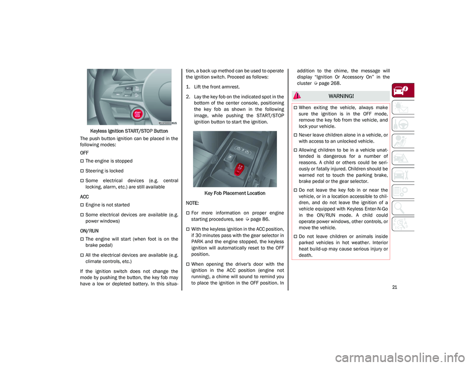
Keyless Ignition START/STOP Button
The push button ignition can be placed in the
following modes:
OFF
The engine is stopped
Steering is locked
Some electrical devices (e.g. central
locking, alarm, etc.) are still available
ACC
Engine is not started
Some electrical devices are available (e.g.
power windows)
ON/RUN
The engine will start (when foot is on the
brake pedal)
All the electrical devices are available (e.g.
climate controls, etc.)
If the ignition switch does not change the
mode by pushing the button, the key fob may
have a low or depleted battery. In this situa -tion, a back up method can be used to operate
the ignition switch. Proceed as follows:
1. Lift the front armrest.
2. Lay the key fob on the indicated spot in the
bottom of the center console, positioning
the key fob as shown in the following
image, while pushing the START/STOP
ignition button to start the ignition.
Key Fob Placement Location
NOTE:
For more information on proper engine
starting procedures, see
Ú
page 86.
With the keyless ignition in the ACC position,
if 30 minutes pass with the gear selector in
PARK and the engine stopped, the keyless
ignition will automatically reset to the OFF
position.
When opening the driver's door with the
ignition in the ACC position (engine not
running), a chime will sound to remind you
to place the ignition in the OFF position. In addition to the chime, the message will
display “Ignition Or Accessory On” in the
cluster
Ú
page 268.
WARNING!
When exiting the vehicle, always make
sure the ignition is in the OFF mode,
remove the key fob from the vehicle, and
lock your vehicle.
Never leave children alone in a vehicle, or
with access to an unlocked vehicle.
Allowing children to be in a vehicle unat -
tended is dangerous for a number of
reasons. A child or others could be seri -
ously or fatally injured. Children should be
warned not to touch the parking brake,
brake pedal or the gear selector.
Do not leave the key fob in or near the
vehicle, or in a location accessible to chil -
dren, and do not leave the ignition of a
vehicle equipped with Keyless Enter-N-Go
in the ON/RUN mode. A child could
operate power windows, other controls, or
move the vehicle.
Do not leave children or animals inside
parked vehicles in hot weather. Interior
heat build-up may cause serious injury or
death.
21_GU_OM_EN_USC_t.book Page 21
Page 62 of 280
GETTING TO KNOW YOUR VEHICLE
60
The sunroof has three preset positions:
Fully closed
Comfort (intermediate opening)
Fully open
NOTE:
You cannot have the sunshade closed when
the sunroof is open.
Opening And Closing The Sunroof
To open the sunroof’s front panel, push the
open/close button toward the rear of the
vehicle to open to the comfort position (half
way). Pushing the button a second time will
open to the fully open position.
To close the sunroof, push the open/close
button toward the front of the vehicle. The roof
will close completely.
The automatic motion can be interrupted in
any position by pushing the open/close button
again.
Venting Sunroof
To bring the roof into vent position, push and
release the vent button.
This type of vent opening can be activated
regardless of the position of the sunroof.
When starting with the roof in the closed posi -
tion, pushing the vent button automatically
causes the sunroof to open to the vent posi -
tion. If the roof is already open, the button
must be held until the roof reaches the
vent-opening position.
Pushing the vent button again during auto -
matic movement of the roof will stop it.
Sunshade Operation
The sunshade is power operated.
Push the Power Shade open/close button
toward the rear of the vehicle to open the sun
shade.
Push the Power Shade open/close button
toward the front of the vehicle to close the sun
shade.
The automatic motion can be interrupted in
any position by pushing the Power Shade
open/close button again.
Pinch Protect Feature
The sunroof has an anti-pinch safety system
capable of detecting the presence of an
obstacle during the closing movement. If an
obstacle is detected, the system intervenes
and the movement of the sunroof is immedi -
ately reversed.
Re-Initialization Procedure
Automatic operation of the sunroof must be
re-initialized in case of faulty sunroof opera -
tion. It may also be necessary to initialize the
sunroof after the vehicle’s battery has been
disconnected and then reconnected.
NOTE:
The anti-pinch safety device is deactivated
during the re-initialization procedure.
WARNING!
Never leave children unattended in a
vehicle, or with access to an unlocked
vehicle. Never leave the key fob in or near
the vehicle, or in a location accessible to chil -
dren. Do not leave the ignition of a vehicle
equipped with keyless ignition in the ON/
RUN mode. Occupants, particularly unat -
tended children, can become entrapped by
the power sunroof while operating the power
sunroof switch. Such entrapment may result
in serious injury or death.
In a collision, there is a greater risk of
being thrown from a vehicle with an open
sunroof. You could also be seriously
injured or killed. Always fasten your seat
belt properly and make sure all passen -
gers are also properly secured.
Do not allow small children to operate the
sunroof. Never allow your fingers, other
body parts, or any object, to project
through the sunroof opening. Injury may
result.
CAUTION!
Do not open the sun roof if a roof rack or
crossbars are fitted. Do not open the sun
roof if there is snow or ice on it: you may
damage it.
21_GU_OM_EN_USC_t.book Page 60
Page 73 of 280
71
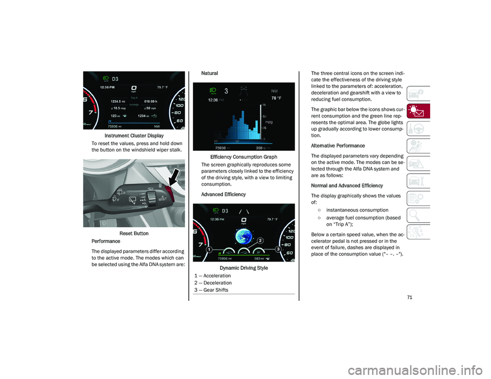
Instrument Cluster Display
To reset the values, press and hold down
the button on the windshield wiper stalk.
Reset Button
Performance
The displayed parameters differ according
to the active mode. The modes which can
be selected using the Alfa DNA system are: Natural
Efficiency Consumption Graph
The screen graphically reproduces some
parameters closely linked to the efficiency
of the driving style, with a view to limiting
consumption.
Advanced Efficiency
Dynamic Driving Style The three central icons on the screen indi
-
cate the effectiveness of the driving style
linked to the parameters of: acceleration,
deceleration and gearshift with a view to
reducing fuel consumption.
The graphic bar below the icons shows cur -
rent consumption and the green line rep -
resents the optimal area. The globe lights
up gradually according to lower consump -
tion.
Alternative Performance
The displayed parameters vary depending
on the active mode. The modes can be se -
lected through the Alfa DNA system and
are as follows:
Normal and Advanced Efficiency
The display graphically shows the values
of:
○ instantaneous consumption
○ average fuel consumption (based on “Trip A”);
Below a certain speed value, when the ac -
celerator pedal is not pressed or in the
event of failure, dashes are displayed in
place of the consumption value ("– –. –").
1 — Acceleration
2 — Deceleration
3 — Gear Shifts
21_GU_OM_EN_USC_t.book Page 71
Page 98 of 280
STARTING AND OPERATING
96
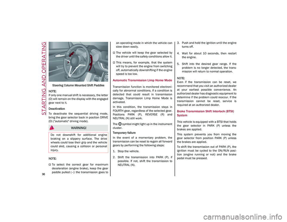
Steering Column Mounted Shift Paddles
NOTE:
If only one manual shift is necessary, the letter
(D) will remain on the display with the engaged
gear next to it.
Deactivation
To deactivate the sequential driving mode,
bring the gear selector back in position DRIVE
(D) ("automatic" driving mode).
NOTE:
To select the correct gear for maximum
deceleration (engine brake), keep the gear
paddle pulled (–): the transmission goes to an operating mode in which the vehicle can
slow down easily.
The vehicle will keep the gear selected by
the driver until the safety conditions allow it.
This means, for example, that the system
will try to prevent the engine from switching
off, automatically downshifting if the engine
speed is too low.
Automatic Transmission Limp Home Mode
Transmission function is monitored electroni
-
cally for abnormal conditions. If a condition is
detected that could result in transmission
damage, Transmission Limp Home Mode is
activated.
In this condition, the transmission stays in
FOURTH gear, regardless of the selected gear.
Positions PARK (P), REVERSE (R) and
NEUTRAL (N) still work.
The symbol might light up in the instrument
cluster.
Temporary failure
In the event of a momentary problem, the
transmission can be reset to regain all forward
gears by performing the following steps:
1. Stop the vehicle.
2. Shift the transmission into PARK (P), if possible. If not, shift the transmission to
NEUTRAL (N). 3. Push and hold the ignition until the engine
turns off.
4. Wait for about 10 seconds, then restart the engine.
5. Shift into the desired gear range. If the problem is no longer detected, the trans -
mission will return to normal operation.
NOTE:
Even if the transmission can be reset, we
recommend that you visit an authorized dealer
at your earliest possible convenience. An
authorized dealer has diagnostic equipment to
determine if the problem could reoccur. If the
transmission cannot be reset, service is
required at an authorized dealer.
Brake Transmission Shift Interlock (BTSI)
System
This vehicle is equipped with a BTSI that holds
the gear selector in PARK (P) unless the
brakes are applied.
This system prevents you from moving the
gear selector from position PARK (P) unless
the brakes are applied.
To shift the transmission out of PARK (P), the
ignition must be cycled to the ON/RUN posi -
tion (engine running or not) and the brake
pedal must be pressed.
WARNING!
Do not downshift for additional engine
braking on a slippery surface. The drive
wheels could lose their grip and the vehicle
could skid, causing a collision or personal
injury.
21_GU_OM_EN_USC_t.book Page 96
Page 106 of 280
STARTING AND OPERATING
104
To access the function on the main menu,
select the following items in order:
1. “Driver Assistance”
2. “Speed Limiter - Set Speed”
By turning the Rotary Pad, the speed increases
by 5 mph (5 km/h), from a minimum of
18 mph (30 km/h) to a maximum of 112 mph
(180 km/h).
Exceeding The Programmed Speed
By fully pressing the accelerator pedal, the
programmed speed can be exceeded even
with the device active (e.g. in the event of over-
taking).
The device is disabled until the speed drops
below the set limit, after which it reactivates
automatically.
Programmed Speed Icon Flashing
The programmed speed will flash in the
following scenarios:
When the accelerator pedal has been fully
pressed and the vehicle has exceeded the
programmed speed.
Activating the system after setting a limit
below the effective speed of the vehicle.
In the event of overtake acceleration.
Deactivation
The feature can be activated/deactivated
through the radio system.
Deactivating The Device
To access this feature, select the “Driver Assis -
tance” widget in the radio system, then select
the following items in sequence:
1. “Speed Limiter”
2. “OFF”
Automatic Deactivation Of The Device
The device deactivates automatically in the
event of fault in the system. In this case,
contact an authorized dealer.
Temporary Signal Loss
When the devices loses the signal, the white
symbol without the speed indication illumi -
nates on the display.
System Failure
If there is a system failure, the amber symbol
illuminates on the display.
CRUISE CONTROL SYSTEMS — IF
EQUIPPED
Cruise Control — If Equipped
When engaged, the Cruise Control takes over
accelerator operations at speeds greater than
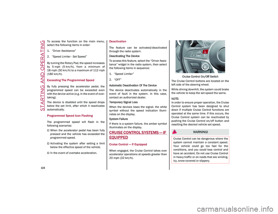
20 mph (32 km/h). Cruise Control On/Off Switch
The Cruise Control buttons are located on the
left side of the steering wheel.
While driving downhill, the system could brake
the vehicle to keep the set speed the same.
NOTE:
In order to ensure proper operation, the Cruise
Control system has been designed to shut
down if multiple Cruise Control functions are
operated at the same time. If this occurs, the
Cruise Control system can be reactivated by
pushing the Cruise Control on/off button and
resetting the desired vehicle set speed.
WARNING!
Cruise Control can be dangerous where the
system cannot maintain a constant speed.
Your vehicle could go too fast for the
conditions, and you could lose control and
have an accident. Do not use Cruise Control
in heavy traffic or on roads that are winding,
icy, snow-covered or slippery.
21_GU_OM_EN_USC_t.book Page 104
Page 108 of 280
STARTING AND OPERATING
106
To Accelerate For Passing
Press the accelerator as you would normally.
When the pedal is released, the vehicle will
return to the set speed.
Using Cruise Control On Hills
The transmission may downshift on hills to
maintain the vehicle set speed.
NOTE:
The Cruise Control system maintains speed up
and down hills. A slight speed change on
moderate hills is normal.
On steep hills, a greater speed loss or gain
may occur so it may be preferable to drive
without Cruise Control.
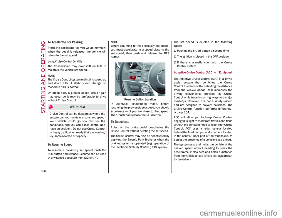
To Resume Speed
To resume a previously set speed, push the
RES button and release. Resume can be used
at any speed above 20 mph (32 km/h).
NOTE:
Before returning to the previously set speed,
you must accelerate to a speed close to the
set speed, then push and release the RES
button.
Resume Button Location
In AutoStick (sequential) mode, before
resuming the previously set speed, you should
accelerate until you are close to that speed.
Then, push and release the RES button.
To Deactivate
A tap on the brake pedal deactivates the
Cruise Control without deleting the set speed.
The Cruise Control may also be deactivated by
applying the Electric Park Brake or when the
braking system is operated (e.g. operation of
the Electronic Stability Control (ESC) system). The set speed is deleted in the following
cases:
Pushing the on/off button a second time
The ignition is placed in the OFF position
If there is a malfunction with the Cruise
Control system
Adaptive Cruise Control (ACC) — If Equipped
The Adaptive Cruise Control (ACC) is a driver
assist system that combines the Cruise
Control functions with controlling the distance
from the vehicle ahead. ACC increases the
driving convenience provided by Cruise
Control while traveling on highways and major
roadways. However, it is not a safety system
and not designed to prevent collisions. The
Cruise Control function performs differently
Ú
page 104.
ACC will allow you to keep Cruise Control
engaged in light to moderate traffic conditions
without the constant need to reset your Cruise
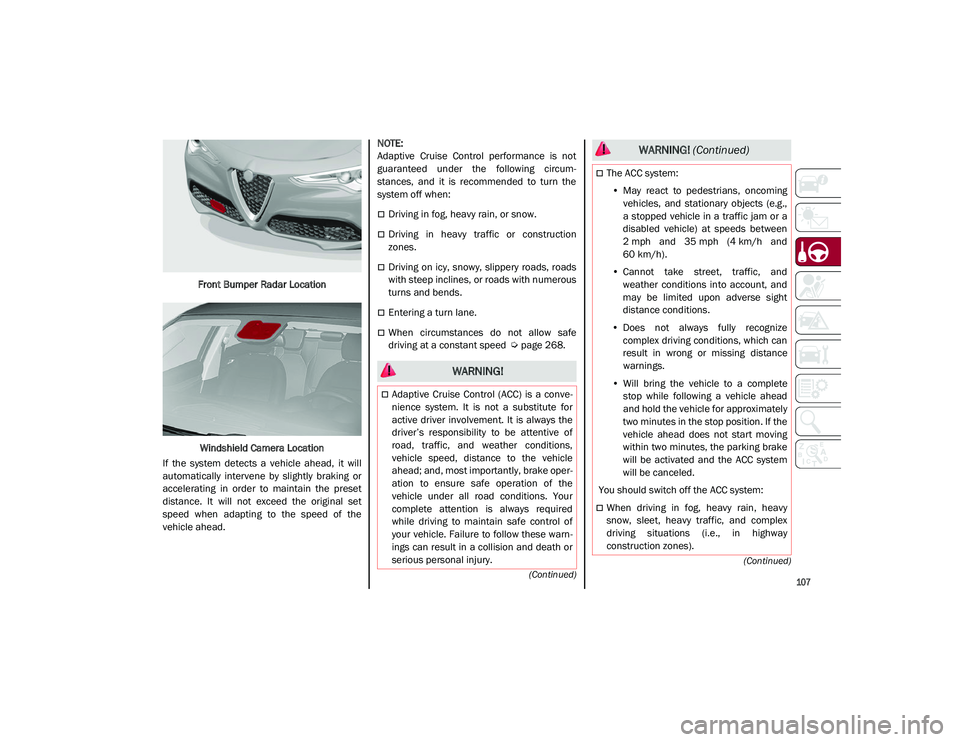
Control. ACC uses a radar sensor located
behind the front bumper and a camera located
in the center/upper part of the windshield, to
detect the presence of a vehicle close ahead.
The system sets and holds the vehicle at the
desired speed without needing to press the
accelerator. It also sets and holds a distance
from the vehicle ahead (these settings are set
by the driver).
WARNING!
Cruise Control can be dangerous where the
system cannot maintain a constant speed.
Your vehicle could go too fast for the
conditions, and you could lose control and
have an accident. Do not use Cruise Control
in heavy traffic or on roads that are winding,
icy, snow-covered or slippery.
21_GU_OM_EN_USC_t.book Page 106
Page 109 of 280
107
(Continued)
(Continued)
Front Bumper Radar Location
Windshield Camera Location
If the system detects a vehicle ahead, it will
automatically intervene by slightly braking or
accelerating in order to maintain the preset
distance. It will not exceed the original set
speed when adapting to the speed of the
vehicle ahead.
NOTE:
Adaptive Cruise Control performance is not
guaranteed under the following circum
-
stances, and it is recommended to turn the
system off when:
Driving in fog, heavy rain, or snow.
Driving in heavy traffic or construction
zones.
Driving on icy, snowy, slippery roads, roads
with steep inclines, or roads with numerous
turns and bends.
Entering a turn lane.
When circumstances do not allow safe
driving at a constant speed
Ú
page 268.
WARNING!
Adaptive Cruise Control (ACC) is a conve -
nience system. It is not a substitute for
active driver involvement. It is always the
driver’s responsibility to be attentive of
road, traffic, and weather conditions,
vehicle speed, distance to the vehicle
ahead; and, most importantly, brake oper -
ation to ensure safe operation of the
vehicle under all road conditions. Your
complete attention is always required
while driving to maintain safe control of
your vehicle. Failure to follow these warn -
ings can result in a collision and death or
serious personal injury.
The ACC system:
• May react to pedestrians, oncoming
vehicles, and stationary objects (e.g.,
a stopped vehicle in a traffic jam or a
disabled vehicle) at speeds between
2 mph and 35 mph (4 km/h and
60 km/h).
• Cannot take street, traffic, and
weather conditions into account, and
may be limited upon adverse sight
distance conditions.
• Does not always fully recognize
complex driving conditions, which can
result in wrong or missing distance
warnings.
• Will bring the vehicle to a complete
stop while following a vehicle ahead
and hold the vehicle for approximately
two minutes in the stop position. If the
vehicle ahead does not start moving
within two minutes, the parking brake
will be activated and the ACC s
ystem
will be canceled.
You should switch off the ACC system:
When driving in fog, heavy rain, heavy
snow, sleet, heavy traffic, and complex
driving situations (i.e., in highway
construction zones).
WARNING! (Continued)
21_GU_OM_EN_USC_t.book Page 107
Page 178 of 280
SAFETY
176
NOTE:
After an accident, remember to cycle the igni-
tion to the OFF position and remove the key
from the ignition switch to avoid draining the
battery. Carefully check the vehicle for fuel
leaks in the engine compartment and on the
ground near the engine compartment and fuel
tank before resetting the system and starting
the engine. If there are no fuel leaks or
damage to the vehicle electrical devices (e.g.
headlights) after an accident, reset the system by following the procedure described below. If
you have any doubt, contact an authorized
dealer.
Enhanced Accident Response System
Reset Procedure
After the event occurs, when the system is
active, a message regarding fuel cutoff is
displayed. Turn the ignition switch from igni
-
tion ACC or ON/RUN to ignition OFF. Carefully
check the vehicle for fuel leaks in the engine compartment and on the ground near the
engine compartment and fuel tank before
resetting the system and starting the engine.
Depending on the nature of the event the left
and right turn signal lights, located in the
instrument panel, may both be blinking and
will continue to blink. In order to move your
vehicle to the side of the road, you must follow
the system reset procedure.
Customer Action
NOTE:
Each step MUST BE held for at least two secondsCustomer Will See
1. Turn ignition OFF. (Turn Signal Switch Must be placed in
Neutral State).
2. Turn ignition ACC. Right turn light BLINKS.
Left turn light is OFF.
3. Turn right turn signal switch ON. Right turn light is ON SOLID.
Left turn light BLINKS.
4. Place turn signal in neutral state. Right turn light is OFF.
Left turn light BLINKS.
5. Turn left turn signal switch ON. Right turn light BLINKS.
Left turn light is ON SOLID.
6. Place turn signal in neutral state. Right turn light BLINKS.
Left turn light is OFF.
7. Turn right turn signal switch ON. Right turn light is ON SOLID.
Left turn light BLINKS.
8. Place turn signal in neutral state. Right turn light is OFF.
Left turn light BLINKS.
21_GU_OM_EN_USC_t.book Page 176