2021 ALFA ROMEO STELVIO alarm
[x] Cancel search: alarmPage 23 of 280
21
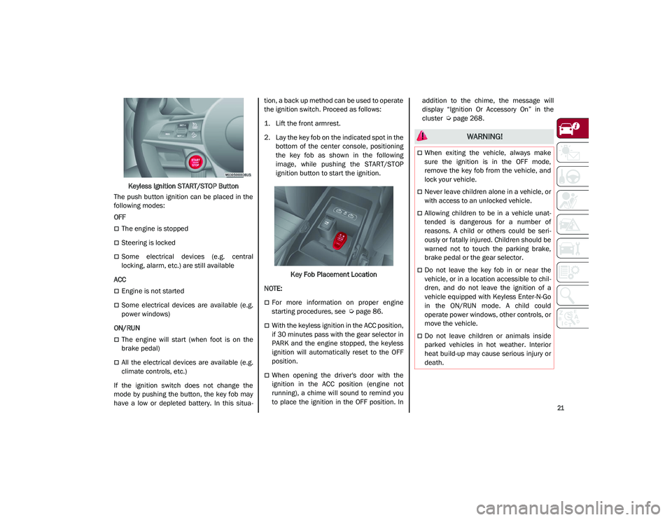
Keyless Ignition START/STOP Button
The push button ignition can be placed in the
following modes:
OFF
The engine is stopped
Steering is locked
Some electrical devices (e.g. central
locking, alarm, etc.) are still available
ACC
Engine is not started
Some electrical devices are available (e.g.
power windows)
ON/RUN
The engine will start (when foot is on the
brake pedal)
All the electrical devices are available (e.g.
climate controls, etc.)
If the ignition switch does not change the
mode by pushing the button, the key fob may
have a low or depleted battery. In this situa -tion, a back up method can be used to operate
the ignition switch. Proceed as follows:
1. Lift the front armrest.
2. Lay the key fob on the indicated spot in the
bottom of the center console, positioning
the key fob as shown in the following
image, while pushing the START/STOP
ignition button to start the ignition.
Key Fob Placement Location
NOTE:
For more information on proper engine
starting procedures, see
Ú
page 86.
With the keyless ignition in the ACC position,
if 30 minutes pass with the gear selector in
PARK and the engine stopped, the keyless
ignition will automatically reset to the OFF
position.
When opening the driver's door with the
ignition in the ACC position (engine not
running), a chime will sound to remind you
to place the ignition in the OFF position. In addition to the chime, the message will
display “Ignition Or Accessory On” in the
cluster
Ú
page 268.
WARNING!
When exiting the vehicle, always make
sure the ignition is in the OFF mode,
remove the key fob from the vehicle, and
lock your vehicle.
Never leave children alone in a vehicle, or
with access to an unlocked vehicle.
Allowing children to be in a vehicle unat -
tended is dangerous for a number of
reasons. A child or others could be seri -
ously or fatally injured. Children should be
warned not to touch the parking brake,
brake pedal or the gear selector.
Do not leave the key fob in or near the
vehicle, or in a location accessible to chil -
dren, and do not leave the ignition of a
vehicle equipped with Keyless Enter-N-Go
in the ON/RUN mode. A child could
operate power windows, other controls, or
move the vehicle.
Do not leave children or animals inside
parked vehicles in hot weather. Interior
heat build-up may cause serious injury or
death.
21_GU_OM_EN_USC_t.book Page 21
Page 25 of 280

23
Remote Start Comfort Systems — If
Equipped
When Remote Start is activated, the heated
steering wheel and front heated seat features
will automatically activate when ambient
temperature is less than 39°F (4°C). These
features will stay on through the duration of
Remote Start.
NOTE:
This feature can be activated through the
radio system. Refer to the Information and
Entertainment System Owner’s Manual
Supplement for further information
VEHICLE SECURITY SYSTEM — IF
EQUIPPED
The Vehicle Security system monitors the
vehicle doors, hood, liftgate, and the keyless
push button ignition for unauthorized opera-
tion. It also monitors movement inside the
passenger compartment (volumetric protec -
tion — if equipped), cutting of battery cables,
and unexpected lifting/tilting of the vehicle
(anti-lift protection — if equipped).
While the Vehicle Security system is armed,
interior switches for door locks are disabled.
If something triggers the alarm, the Vehicle
Security system will provide the following
audible and visible signals:
The horn will pulse
The turn signals will flash
The vehicle security light in the instrument
cluster will flash
NOTE:
The Vehicle Security system is activated by the
Engine Immobilizer system, which is automati -
cally activated when you get out of the vehicle
with the key fob and lock the doors.
To Arm The System
Follow these steps to arm the Vehicle Security
system:
1. Make sure the vehicle’s ignition is placed in the OFF position.
2. Perform one of the following methods to lock the vehicle:
• Push the lock button on the interior
power door lock switch with the driver
and/or passenger door open.
• Push the lock button on the exterior
Passive Entry door handle with a valid
key fob available in the same exterior
zone
Ú
page 25.
• Push the lock button on the key fob.
3. If any doors (or liftgate) are open, close them.
To Disarm The System
The Vehicle Security system can be disarmed
using any of the following methods:
Push the unlock button on the key fob.
Grab the Passive Entry door handle to
unlock the door
Ú
page 25.
Cycle the ignition out of the OFF position to
disarm the system.
NOTE:
The driver's door key cylinder and liftgate
button on the key fob cannot arm or disarm
the Vehicle Security system. Use of the door
key cylinder when the system is armed will
sound the alarm when the door is opened.
When the Vehicle Security system is armed,
the interior power door lock switches will
not unlock the doors.
The Vehicle Security system is designed to
protect your vehicle. However, you can create
conditions where the system will give you a
false alarm. If one of the previously described
arming sequences has occurred, the Vehicle
Security system will arm, regardless of
whether you are in the vehicle or not. If you
remain in the vehicle and open a door, the
alarm will sound. If this occurs, disarm the
Vehicle Security system.
If the Vehicle Security system is armed and the
battery becomes disconnected, the Vehicle
Security system will remain armed when the
21_GU_OM_EN_USC_t.book Page 23
Page 26 of 280
GETTING TO KNOW YOUR VEHICLE
24
(Continued)
battery is reconnected; the exterior lights will
flash, and the horn will sound. If this occurs,
disarm the Vehicle Security system.
NOTE:
The alarm does not disarm when the doors are
unlocked by inserting the blade of the emer-
gency key (found inside the key fob) into the
door handle lock cylinder.
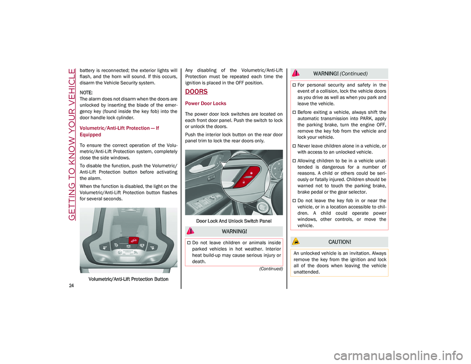
Volumetric/Anti-Lift Protection — If
Equipped
To ensure the correct operation of the Volu -
metric/Anti-Lift Protection system, completely
close the side windows.
To disable the function, push the Volumetric/
Anti-Lift Protection button before activating
the alarm.
When the function is disabled, the light on the
Volumetric/Anti-Lift Protection button flashes
for several seconds.
Volumetric/Anti-Lift Protection Button Any disabling of the Volumetric/Anti-Lift
Protection must be repeated each time the
ignition is placed in the OFF position.
DOORS
Power Door Locks
The power door lock switches are located on
each front door panel. Push the switch to lock
or unlock the doors.
Push the interior lock button on the rear door
panel trim to lock the rear doors only.
Door Lock And Unlock Switch Panel
WARNING!
Do not leave children or animals inside
parked vehicles in hot weather. Interior
heat build-up may cause serious injury or
death.
For personal security and safety in the
event of a collision, lock the vehicle doors
as you drive as well as when you park and
leave the vehicle.
Before exiting a vehicle, always shift the
automatic transmission into PARK, apply
the parking brake, turn the engine OFF,
remove the key fob from the vehicle and
lock your vehicle.
Never leave children alone in a vehicle, or
with access to an unlocked vehicle.
Allowing children to be in a vehicle unat -
tended is dangerous for a number of
reasons. A child or others could be seri -
ously or fatally injured. Children should be
warned not to touch the parking brake,
brake pedal or the gear selector.
Do not leave the key fob in or near the
vehicle, or in a location accessible to chil -
dren. A child could operate power
windows, other controls, or move the
vehicle.
CAUTION!
An unlocked vehicle is an invitation. Always
remove the key from the ignition and lock
all of the doors when leaving the vehicle
unattended.
WARNING! (Continued)
21_GU_OM_EN_USC_t.book Page 24
Page 29 of 280
27
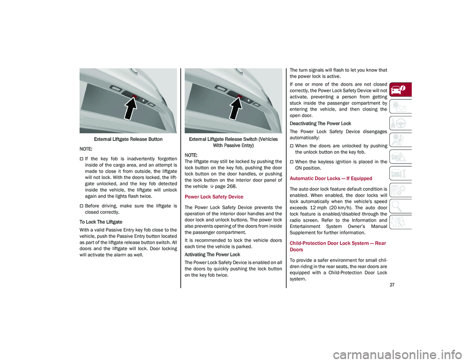
External Liftgate Release Button
NOTE:
If the key fob is inadvertently forgotten
inside of the cargo area, and an attempt is
made to close it from outside, the liftgate
will not lock. With the doors locked, the lift -
gate unlocked, and the key fob detected
inside the vehicle, the liftgate will unlock
again and the lights flash twice.
Before driving, make sure the liftgate is
closed correctly.
To Lock The Liftgate
With a valid Passive Entry key fob close to the
vehicle, push the Passive Entry button located
as part of the liftgate release button switch. All
doors and the liftgate will lock. Door locking
will activate the alarm as well. External Liftgate Release Switch (Vehicles
With Passive Entry)
NOTE:
The liftgate may still be locked by pushing the
lock button on the key fob, pushing the door
lock button on the door handles, or pushing
the lock button on the interior door panel of
the vehicle
Ú
page 268.
Power Lock Safety Device
The Power Lock Safety Device prevents the
operation of the interior door handles and the
door lock and unlock buttons. The power lock
also prevents opening of the doors from inside
the passenger compartment.
It is recommended to lock the vehicle doors
each time the vehicle is parked.
Activating The Power Lock
The Power Lock Safety Device is enabled on all
the doors by quickly pushing the lock button
on the key fob twice. The turn signals will flash to let you know that
the power lock is active.
If one or more of the doors are not closed
correctly, the Power Lock Safety Device will not
activate, preventing a person from getting
stuck inside the passenger compartment by
entering the vehicle, and then closing the
open door.
Deactivating The Power Lock
The Power Lock Safety Device disengages
automatically:
When the doors are unlocked by pushing
the unlock button on the key fob.
When the keyless ignition is placed in the
ON position.
Automatic Door Locks — If Equipped
The auto door lock feature default condition is
enabled. When enabled, the door locks will
lock automatically when the vehicle's speed
exceeds 12 mph (20 km/h). The auto door
lock feature is enabled/disabled through the
radio screen. Refer to the Information and
Entertainment System Owner’s Manual
Supplement for further information.
Child-Protection Door Lock System — Rear
Doors
To provide a safer environment for small chil
-
dren riding in the rear seats, the rear doors are
equipped with a Child-Protection Door Lock
system.
21_GU_OM_EN_USC_t.book Page 27
Page 79 of 280
77
also reduces fuel efficiency and tire tread life,
and may affect the vehicle’s handling and
stopping ability.
Please note that the TPMS is not a substitute
for proper tire maintenance, and it is the
driver’s responsibility to maintain correct tire
pressure, even if under inflation has not
reached the level to trigger illumination of the
TPMS low tire pressure telltale.
Your vehicle has also been equipped with a
TPMS malfunction indicator to indicate when
the system is not operating properly. The
TPMS malfunction indicator is combined with
the low tire pressure telltale. When the system
detects a malfunction, the telltale will flash for
approximately one minute and then remain
continuously illuminated. This sequence will
continue upon subsequent vehicle start-ups
as long as the malfunction exists. When the
malfunction indicator is illuminated, the
system may not be able to detect or signal low
tire pressure as intended. TPMS malfunctions
may occur for a variety of reasons, including
the installation of replacement or alternate
tires or wheels on the vehicle that prevent the
TPMS from functioning properly. Always check
the TPMS malfunction telltale after replacing
one or more tires or wheels on your vehicle to
ensure that the replacement or alternate tires
and wheels allow the TPMS to continue to
function properly.
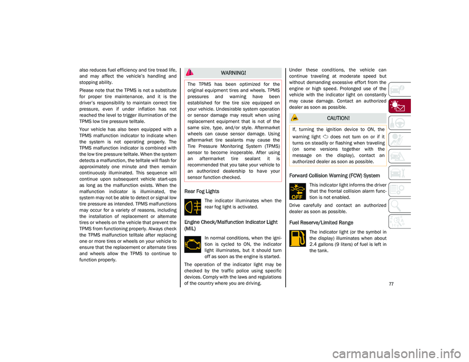
Rear Fog Lights
The indicator illuminates when the
rear fog light is activated.
Engine Check/Malfunction Indicator Light
(MIL)
In normal conditions, when the igni-
tion is cycled to ON, the indicator
light illuminates, but it should turn
off as soon as the engine is started.
The operation of the indicator light may be
checked by the traffic police using specific
devices. Comply with the laws and regulations
of the country where you are driving. Under these conditions, the vehicle can
continue traveling at moderate speed but
without demanding excessive effort from the
engine or high speed. Prolonged use of the
vehicle with the indicator light on constantly
may cause damage. Contact an authorized
dealer as soon as possible.
Forward Collision Warning (FCW) System
This indicator light informs the driver
that the frontal collision alarm func
-
tion is not enabled.
Drive carefully and contact an authorized
dealer as soon as possible.
Fuel Reserve/Limited Range
The indicator light (or the symbol in
the display) illuminates when about
2.4 gallons (9 liters) of fuel is left in
the tank.
WARNING!
The TPMS has been optimized for the
original equipment tires and wheels. TPMS
pressures and warning have been
established for the tire size equipped on
your vehicle. Undesirable system operation
or sensor damage may result when using
replacement equipment that is not of the
same size, type, and/or style. Aftermarket
wheels can cause sensor damage. Using
aftermarket tire sealants may cause the
Tire Pressure Monitoring System (TPMS)
sensor to become inoperable. After using
an aftermarket tire sealant it is
recommended that you take your vehicle to
an authorized dealership to have your
sensor function checked.
CAUTION!
If, turning the ignition device to ON, the
warning light does not turn on or if it
turns on steadily or flashing when traveling
(on some versions together with the
message on the display), contact an
authorized dealer as soon as possible.
21_GU_OM_EN_USC_t.book Page 77
Page 82 of 280
GETTING TO KNOW YOUR INSTRUMENT PANEL
80
the oil level can be checked on the display
upon entering the vehicle and also by acti-
vating the “Oil level” function on the Informa -
tion and Entertainment System.
Contact an authorized dealer as soon as
possible.
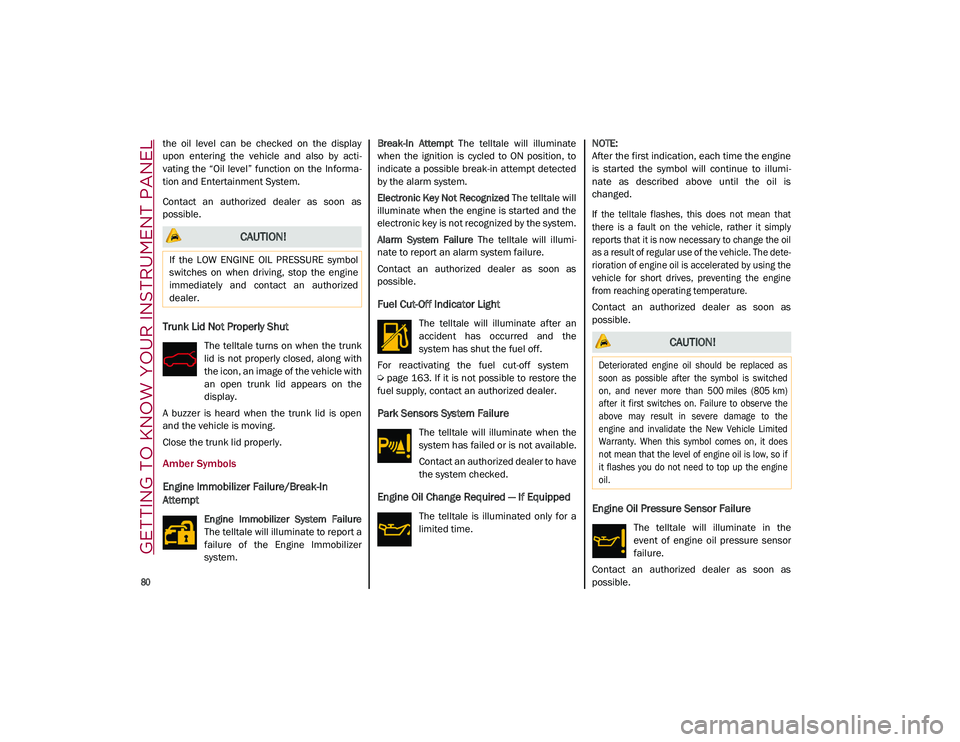
Trunk Lid Not Properly Shut
The telltale turns on when the trunk
lid is not properly closed, along with
the icon, an image of the vehicle with
an open trunk lid appears on the
display.
A buzzer is heard when the trunk lid is open
and the vehicle is moving.
Close the trunk lid properly.
Amber Symbols
Engine Immobilizer Failure/Break-In
Attempt
Engine Immobilizer System Failure
The telltale will illuminate to report a
failure of the Engine Immobilizer
system. Break-In Attempt
The telltale will illuminate
when the ignition is cycled to ON position, to
indicate a possible break-in attempt detected
by the alarm system.
Electronic Key Not Recognized The telltale will
illuminate when the engine is started and the
electronic key is not recognized by the system.
Alarm System Failure The telltale will illumi -
nate to report an alarm system failure.
Contact an authorized dealer as soon as
possible.
Fuel Cut-Off Indicator Light
The telltale will illuminate after an
accident has occurred and the
system has shut the fuel off.
For reactivating the fuel cut-off system
Ú
page 163. If it is not possible to restore the
fuel supply, contact an authorized dealer.
Park Sensors System Failure
The telltale will illuminate when the
system has failed or is not available.
Contact an authorized dealer to have
the system checked.
Engine Oil Change Required — If Equipped
The telltale is illuminated only for a
limited time.
NOTE:
After the first indication, each time the engine
is started the symbol will continue to illumi
-
nate as described above until the oil is
changed.
If the telltale flashes, this does not mean that
there is a fault on the vehicle, rather it simply
reports that it is now necessary to change the oil
as a result of regular use of the vehicle. The dete -
rioration of engine oil is accelerated by using the
vehicle for short drives, preventing the engine
from reaching operating temperature.
Contact an authorized dealer as soon as
possible.Engine Oil Pressure Sensor Failure
The telltale will illuminate in the
event of engine oil pressure sensor
failure.
Contact an authorized dealer as soon as
possible.
CAUTION!
If the LOW ENGINE OIL PRESSURE symbol
switches on when driving, stop the engine
immediately and contact an authorized
dealer.
CAUTION!
Deteriorated engine oil should be replaced as
soon as possible after the symbol is switched
on, and never more than 500 miles (805 km)
after it first switches on. Failure to observe the
above may result in severe damage to the
engine and invalidate the New Vehicle Limited
Warranty. When this symbol comes on, it does
not mean that the level of engine oil is low, so if
it flashes you do not need to top up the engine
oil.
21_GU_OM_EN_USC_t.book Page 80
Page 161 of 280

159
The function of this system can also be tempo-
rarily reduced due to obstructions such as
mud, dirt or ice on the fascia/bumper. In such
cases, a dedicated message will be shown on
the display and the system will be deactivated.
This message can sometimes appear in condi -
tions of high reflectivity (e.g. tunnels with
reflective tiles or ice or snow). When the condi -
tions limiting the system functions end, it will
go back to normal and complete operation.
In certain cases, this dedicated message
could be displayed when the radar is not
detecting any vehicles or objects within its
view range.
If atmospheric conditions are not the reason
behind this message, check if the sensor is
dirty. It could be necessary to clean or remove
any obstructions in the area.
If the message appears frequently, even in the
absence of atmospheric conditions such as
snow, rain, mud or other obstructions, contact
an authorized dealer for a sensor alignment
check.
In the absence of visible obstructions, manu -
ally removing the decorative cover trim and
cleaning the radar surface could be required.
Have this operation performed at an autho -
rized dealer.
NOTE:
It is recommended that you do not install
devices, accessories or aerodynamic attach
-
ments in front of the sensor or darken it in any
way, as this can compromise the correct func -
tioning of the system.
Frontal Collision Alarm With Active Braking — If
Equipped
If this function is selected, the brakes are
operated to reduce the speed of the vehicle in
the event of potential frontal impact.
This function applies an additional braking
pressure if the braking pressure applied by the
driver does not suffice to prevent potential
frontal impact.
The function is active with speed above 2 mph
(4 km/h).
NOTE:
When using an automatic car wash it is recom -
mended to deactivate the system through the
settings of the radio system. The system may
detect the presence of a car, a wall or another
obstacle and activate.
Driving In Special Conditions
In certain driving conditions, system interven -
tion might be unexpected or delayed. The
driver must therefore be very careful, keeping
control of the vehicle to drive in complete
safety.Driving close to a bend.
The vehicle ahead is leaving a roundabout.
Vehicles with small dimensions and/or not
aligned in the driving lane.
Lane change by other vehicles.
Vehicles traveling at right angles to the
vehicle.
NOTE:
In particularly complex traffic conditions,
the driver can deactivate the system manu -
ally through the Information and Entertain -
ment system.
If the driver depresses the brake pedal fully
or makes an excessive steering maneuver
during system operation, the automatic
braking function may deactivate (e.g. to
allow a possible maneuver to avoid the
obstacle).
The FCW system is automatically deacti -
vated when operating in race mode and a
warning message will be displayed on the
instrument cluster.
21_GU_OM_EN_USC_t.book Page 159
Page 174 of 280
SAFETY
172
damage by themselves are not good indicators
of whether or not an air bag should have
deployed.
Seat belts are necessary for your protection in
all collisions, and also are needed to help keep
you in position, away from an inflating air bag.
When the Occupant Restraint Controller (ORC)
detects a collision requiring the front air bags,
it signals the inflator units. A large quantity of
non-toxic gas is generated to inflate the front
air bags.
The steering wheel hub trim cover and the
upper passenger side of the instrument panel
separate and fold out of the way as the air
bags inflate to their full size. The front air bags
fully inflate in less time than it takes to blink
your eyes. The front air bags then quickly
deflate while helping to restrain the driver and
front passenger.
Knee Impact Bolsters
The Knee Impact Bolsters help protect the
knees of the driver and front passenger, and
position the front occupants for improved
interaction with the front air bags.
Supplemental Driver And Front Passenger
Knee Air Bags
This vehicle is equipped with a Supplemental
Driver Knee Air Bag mounted in the instrument
panel below the steering column and a
Supplemental Passenger Knee Air Bag
mounted in the instrument panel below the
glove compartment. The Supplemental Knee
Air Bags provide enhanced protection during a
frontal impact by working together with the
seat belts, pretensioners, and front air bags.
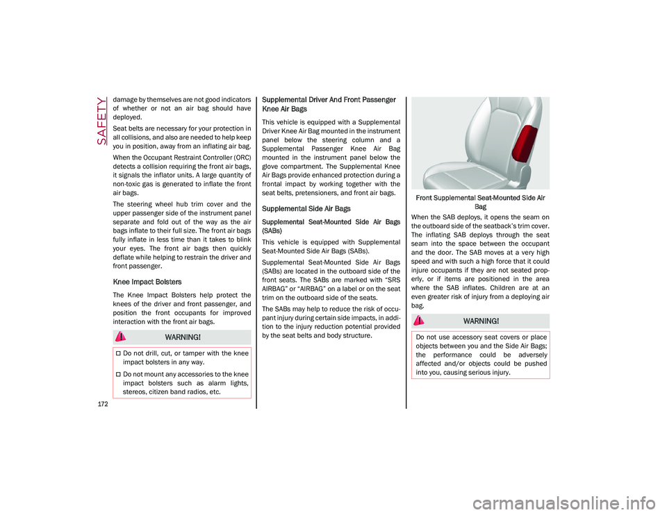
Supplemental Side Air Bags
Supplemental Seat-Mounted Side Air Bags
(SABs)
This vehicle is equipped with Supplemental
Seat-Mounted Side Air Bags (SABs).
Supplemental Seat-Mounted Side Air Bags
(SABs) are located in the outboard side of the
front seats. The SABs are marked with “SRS
AIRBAG” or “AIRBAG” on a label or on the seat
trim on the outboard side of the seats.
The SABs may help to reduce the risk of occu-
pant injury during certain side impacts, in addi-
tion to the injury reduction potential provided
by the seat belts and body structure. Front Supplemental Seat-Mounted Side Air
Bag
When the SAB deploys, it opens the seam on
the outboard side of the seatback’s trim cover.
The inflating SAB deploys through the seat
seam into the space between the occupant
and the door. The SAB moves at a very high
speed and with such a high force that it could
injure occupants if they are not seated prop -
erly, or if items are positioned in the area
where the SAB inflates. Children are at an
even greater risk of injury from a deploying air
bag.
WARNING!
Do not drill, cut, or tamper with the knee
impact bolsters in any way.
Do not mount any accessories to the knee
impact bolsters such as alarm lights,
stereos, citizen band radios, etc.
WARNING!
Do not use accessory seat covers or place
objects between you and the Side Air Bags;
the performance could be adversely
affected and/or objects could be pushed
into you, causing serious injury.
21_GU_OM_EN_USC_t.book Page 172