2021 ALFA ROMEO STELVIO spare wheel
[x] Cancel search: spare wheelPage 14 of 280

12
JUMP STARTING .................................... 201
Remote Battery Connection Posts......202
Jump Starting Procedure.....................203
Bump Starting ..................................204
ENGINE OVERHEATING ......................... 204 MANUAL PARK RELEASE ...................... 205TOWING A DISABLED VEHICLE ............. 205
Four-Wheel Drive (AWD) Models .........206
TOW EYES .............................................. 206
ENHANCED ACCIDENT RESPONSE
SYSTEM (EARS) ..................................... 207EVENT DATA RECORDER (EDR) ............ 207
SERVICING AND MAINTENANCE
SCHEDULED SERVICING ....................... 208
Periodic Checks ...................................208
Heavy Usage Of The Vehicle ...............208
Maintenance Plan (2.0L Engine) ........209
Maintenance Plan (2.9L Engine) ........212
ENGINE COMPARTMENT....................... 214
Checking Levels — 2.0L Engine .......... 214
Checking Levels — 2.9L Engine .......... 215
Engine Oil ............................................. 215
Engine Coolant Fluid............................216
Washer Fluid For Windshield/
Headlights ............................................ 217 Brake Fluid ...........................................217
Automatic Transmission Activation
System Oil ............................................ 217 Useful Advice For Extending The Life Of
Your Battery..........................................217 Battery ..................................................217
Pressure Washing ................................ 218
BATTERY RECHARGING ......................... 218
Important Notes .................................. 218
VEHICLE MAINTENANCE ........................ 219
Engine Oil ............................................. 219
Engine Oil Filter ................................... 220
Engine Air Cleaner Filter ..................... 220
Air Conditioning System
Maintenance........................................ 220 Lubricating Moving Parts Of The
Bodywork ............................................. 220 Windshield Wiper................................. 221
Exhaust System ................................... 222
Cooling System .................................... 223
Braking System.................................... 224
Automatic Transmission ..................... 225
Replacing The Battery ......................... 225
Fuses .................................................... 225
Bulb Replacement ............................... 229
TIRES ...................................................... 233
Tire Safety Information .................... 233
Tires — General Information .............. 239
Spare Tires — If Equipped .................. 244
Wheel And Wheel Trim Care ............ 245
Tire Types ............................................. 246
Tire Chains and Traction Devices ....... 247
Tire Rotation Recommendations........ 247
DEPARTMENT OF TRANSPORTATION
UNIFORM TIRE QUALITY GRADES ......... 248
Treadwear ............................................ 248
Traction Grades ................................... 248
Temperature Grades ........................... 248
STORING THE VEHICLE ......................... 249 BODYWORK ........................................... 249
Protection Against Atmospheric
Agents .................................................. 249 Corrosion Warranty ............................. 250
Preserving The Bodywork .................. 250
INTERIORS ............................................. 251
Seats And Fabric Parts ....................... 251
Leather Seats ...................................... 251
Plastic And Coated Parts .................... 251
Alcantara Parts — If Equipped ............ 251
Genuine Leather Parts........................ 251
Carbon Fiber Parts .............................. 252
TECHNICAL SPECIFICATIONS
VEHICLE IDENTIFICATION
NUMBER (VIN) ....................................... 253
Vehicle Identification Number............ 253
Vehicle Identification Number
(VIN) Plate ............................................ 253
ENGINE .................................................. 254
POWER SUPPLY ..................................... 255 TRANSMISSION ..................................... 255BRAKES.................................................. 255
SUSPENSION ......................................... 256
STEERING .............................................. 256
DIMENSIONS ......................................... 257
Luggage Compartment Volume ......... 259
WEIGHTS ................................................ 259
21_GU_OM_EN_USC_t.book Page 12
Page 141 of 280
139
(Continued)
Consider the following items when computing
the weight on the rear axle of the vehicle:
The tongue weight of the trailer.
The weight of any other type of cargo or
equipment put in or on your vehicle.
The weight of the driver and all passengers.
NOTE:
Remember that everything put into or on the
trailer adds to the load on your vehicle. Also,
additional factory-installed options or
dealer-installed options must be considered
as part of the total load on your vehicle. Refer
to the “Tire And Loading Information” placard
for the maximum combined weight of occu -
pants and cargo for your vehicle.
Towing Requirements
To promote proper break-in of your new
vehicle drivetrain components, the following
guidelines are recommended:
Towing Requirements — Tires
Do not attempt to tow a trailer while using a
compact spare tire.
Do not drive more than 50 mph (80 km/h)
when towing while using a full size spare
tire.
Proper tire inflation pressures are essential
to the safe and satisfactory operation of
your vehicle.
Check the trailer tires for proper tire infla -
tion pressures before trailer usage.
Check for signs of tire wear or visible tire
damage before towing a trailer.
Replacing tires with a higher load carrying
capacity will not increase the vehicle's
GVWR and GAWR limits.
For proper tire inflation procedures
Ú
page 233.
WARNING!
Improper towing can lead to a collision.
Follow these guidelines to make your trailer
towing as safe as possible:
Make certain that the load is secured in
the trailer and that it will not shift during
travel. When trailering cargo that is not
fully secured, dynamic load shifts can
occur that may be difficult for the driver to
control. You could lose control of your
vehicle and have a collision.
When hauling cargo, or towing a trailer, do
not overload your vehicle or trailer. Over -
loading can cause a loss of control, poor
performance, or damage to brakes, axle,
engine, transmission, steering, suspen -
sion, chassis structure, or tires.
Safety chains must always be used
between your vehicle and trailer. Always
connect the chains to the frame or hook
retainers of the vehicle hitch. Cross the
chains under the trailer tongue and allow
enough slack for turning corners.
Vehicles with trailers should not be parked
on a grade. When parking, apply the
parking brake on the tow vehicle. Put the
tow vehicle transmission in PARK. Always
block or "chock" the trailer wheels.
GCWR must not be exceeded.
Total weight must be distributed between
the tow vehicle and the trailer such that
the following four ratings are not
exceeded:
• GVWR
• GTW
• GAWR
• Tongue weight rating for the trailer
hitch utilized.
WARNING! (Continued) CAUTION!
Do not tow a trailer at all during the first
500 miles (805 km) the new vehicle is
driven. The engine, axle or other parts
could be damaged.
Then, during the first 500 miles (805 km)
that a trailer is towed, do not drive over
50 mph (80 km/h) and do not make
starts at full throttle. This helps the engine
and other parts of the vehicle wear in at
the heavier loads.
21_GU_OM_EN_USC_t.book Page 139
Page 192 of 280
SAFETY
190
(Continued)
(Continued)
Periodic Safety Checks You Should Make
Outside The Vehicle
Tires
Examine tires for excessive tread wear and
uneven wear patterns. Check for stones, nails,
glass, or other objects lodged in the tread or
sidewall. Inspect the tread for cuts and cracks.
Inspect sidewalls for cuts, cracks, and bulges.
Check the wheel nuts for tightness. Check the
tires (including spare) for proper cold inflation
pressure.
Lights
Have someone observe the operation of brake
lights and exterior lights while you work the controls. Check turn signal and high beam
indicator lights on the instrument panel.
Door Latches
Check for proper closing, latching, and locking.
Fluid Leaks
Check area under the vehicle after overnight
parking for fuel, coolant, oil, or other fluid
leaks. Also, if gasoline fumes are detected or if
fuel, or brake fluid leaks are suspected, the
cause should be located and corrected imme
-
diately.
Exhaust Gas
ONLY use the driver’s side floor mat on the
driver’s side floor area. To check for inter -
ference, with the vehicle properly parked
with the engine off, fully depress the
accelerator, the brake, and the clutch
pedal (if present) to check for interfer -
ence. If your floor mat interferes with the
operation of any pedal, or is not secure to
the floor, remove the floor mat from the
vehicle and place the floor mat in your
trunk.
ONLY use the passenger’s side floor mat
on the passenger’s side floor area.
ALWAYS make sure objects cannot fall or
slide into the driver’s side floor area when
the vehicle is moving. Objects can become
trapped under accelerator, brake, or
clutch pedals and could cause a loss of
vehicle control.
NEVER place any objects under the floor
mat (e.g., towels, keys, etc.). These
objects could change the position of the
floor mat and may cause interference with
the accelerator, brake, or clutch pedals.
WARNING! (Continued)
If the vehicle carpet has been removed
and re-installed, always properly attach
carpet to the floor and check the floor mat
fasteners are secure to the vehicle carpet.
Fully depress each pedal to check for
interference with the accelerator, brake,
or clutch pedals then re-install the floor
mats.
It is recommended to only use mild soap
and water to clean your floor mats. After
cleaning, always check your floor mat has
been properly installed and is secured to
your vehicle using the floor mat fasteners
by lightly pulling mat.
WARNING! (Continued)
WARNING!
Exhaust gases can injure or kill. They
contain carbon monoxide (CO), which is
colorless and odorless. Breathing it can
make you unconscious and can eventually
poison you. To avoid breathing (CO), follow
these safety tips:
Do not run the engine in a closed garage
or in confined areas any longer than
needed to move your vehicle in or out of
the area.
If you are required to drive with the trunk/lift -
gate/rear doors open, make sure that all
windows are closed and the climate control
BLOWER switch is set at high speed. DO NOT
use the recirculation mode.
21_GU_OM_EN_USC_t.book Page 190
Page 197 of 280
195
(Continued)
Frequently Asked Questions:
What happens if I accidentally push the SOS -
Emergency Call Button? You have 10 seconds
after pushing the emergency button to cancel
the call. To cancel the call, push the button
again.
What type of information is sent when I make
an SOS - Emergency Call from my vehicle?
Certain vehicle information, such as the VIN, is
transmitted along with last known GPS loca-
tion. Also note that emergency service opera -
tors may record conversations and sounds
within your vehicle once a connection is made,
and by using the service you consent to having
this information shared.
When can I use the SOS - Emergency
Call button? You can ONLY use the
SOS - Emergency Call button to
make a call if you or someone else
needs emergency assistance.
JACKING AND TIRE CHANGING
General Instructions
This vehicle can be equipped with a Tire
Service Kit
Ú
page 198.
As an alternative to the Tire Service Kit, the
vehicle may be purchased with a compact
spare tire
Ú
page 196.
Jack Information And Usage Precautions
Jack Information
The jack weighs 4.4 lb (2 kg).
The jack requires no adjustment.
The jack cannot be repaired, and in the
event of a fault it must be replaced by
another factory replacement.
No tool other than its extension lever may
be fitted on the jack.
Jack Maintenance
Prevent any dirt from depositing on the
"worm screw".
Keep the "worm screw" lubricated.
Never modify the jack.
Conditions Of Non-Use Of The Jack
Temperatures below −40°F (−40°C).
On sandy or muddy ground
On uneven ground
On steep slopes in extreme weather condi -
tions.
In direct contact with the engine or for
repairs under the vehicle
On boats
WARNING!
Do not attempt to change a tire on the
side of the vehicle close to moving traffic.
Pull far enough off the road to avoid the
danger of being hit when operating the
jack or changing the wheel.
Being under a jacked-up vehicle is
dangerous. The vehicle could slip off the
jack and fall on you. You could be crushed.
Never put any part of your body under a
vehicle that is on a jack. If you need to get
under a raised vehicle, take it to a service
center where it can be raised on a lift.
Never start or run the engine while the
vehicle is on a jack.
The jack is designed to be used as a tool
for changing tires only. The jack should
not be used to lift the vehicle for service
purposes. The vehicle should be jacked on
a firm level surface only. Avoid ice or slip -
pery areas.
WARNING! (Continued)
21_GU_OM_EN_USC_t.book Page 195
Page 198 of 280
IN CASE OF EMERGENCY
196
Changing Procedure
1. Park the vehicle on a firm, level surface.Avoid ice or slippery areas.
2. Turn on the Hazard Warning Flashers.
3. Apply the electric park brake.
4. Place the gear selector into PARK (P).
5. Place the ignition in the OFF mode.
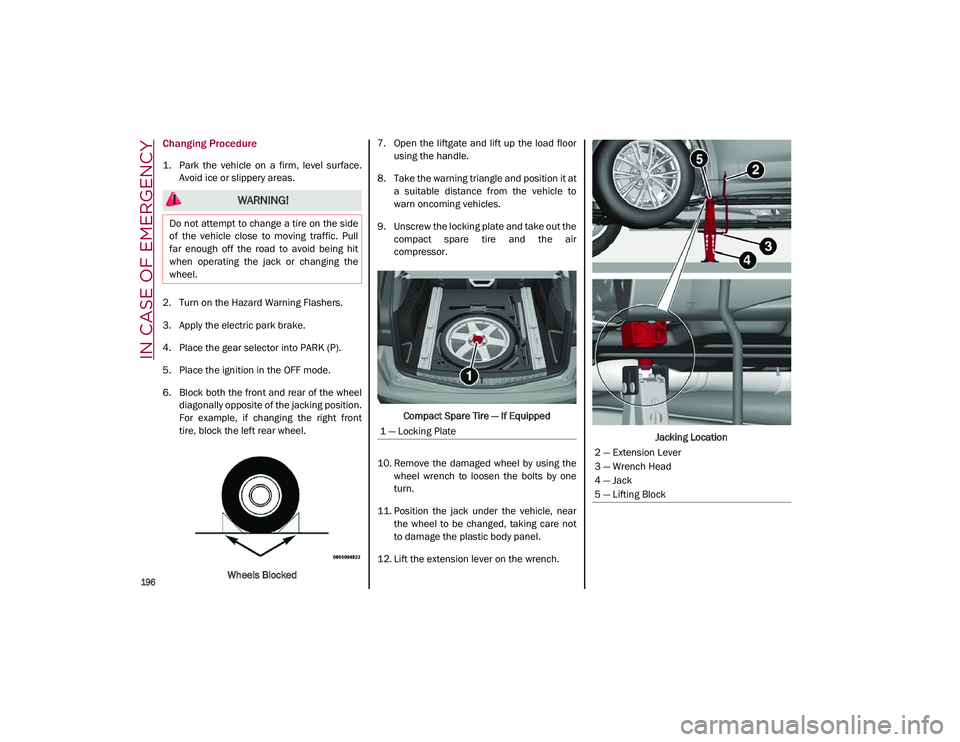
6. Block both the front and rear of the wheel diagonally opposite of the jacking position.
For example, if changing the right front
tire, block the left rear wheel.
Wheels Blocked 7. Open the liftgate and lift up the load floor
using the handle.
8. Take the warning triangle and position it at a suitable distance from the vehicle to
warn oncoming vehicles.
9. Unscrew the locking plate and take out the compact spare tire and the air
compressor.
Compact Spare Tire — If Equipped
10. Remove the damaged wheel by using the wheel wrench to loosen the bolts by one
turn.
11. Position the jack under the vehicle, near the wheel to be changed, taking care not
to damage the plastic body panel.
12. Lift the extension lever on the wrench. Jacking Location
WARNING!
Do not attempt to change a tire on the side
of the vehicle close to moving traffic. Pull
far enough off the road to avoid being hit
when operating the jack or changing the
wheel.
1 — Locking Plate
2 — Extension Lever
3 — Wrench Head
4 — Jack
5 — Lifting Block
21_GU_OM_EN_USC_t.book Page 196
Page 199 of 280

197
13. Rotate the extension lever clockwise untilthe round pin on the jack engages in the
hole in the lifting block located about
6 inches (15 cm) from the outside edge of
the body. The lifting points are marked by
triangles visible on the plastic body
panel.
Jacking Point Indicators
14. Raise the vehicle by turning the jack screw clockwise, using the swivel wrench. Raise
the vehicle only until the tire just clears the
surface and enough clearance is obtained
to install the compact spare tire. Minimum
tire lift provides maximum stability. 15. Remove the five wheel bolts and take the
wheel off.
16. Make sure the contact surfaces between compact spare tire and hub are clean so
that the fastening bolts will not come
loose.
17. Fit the compact spare tire by inserting the first wheel bolt for two threads into the
hole closest to the valve.
18. Take the wheel wrench and tighten the wheel bolts.
19. Inflate the compact spare tire by removing the cap from its inflation valve and
screwing on the compressor inflation hose
fitting. 20. Make sure that the switch on the
compressor is in the (off) O position, open
the liftgate and insert the plug into the
power socket in the cargo area, or on the
center console and start the engine. Place
the on/off switch in the (on) I position.
Attaching Compressor To Tire
21. Inflate the compact spare tire to a pres -
sure of 43.5 psi (3 bar).
NOTE:
If spare tire is overinflated, be sure to lower
the psi in the tire to the recommended amount
by using the deflation button on the air
compressor.
22. Operate the wheel wrench on the jack to lower the vehicle.
CAUTION!
Do not attempt to raise the vehicle by
jacking on locations other than those
indicated in the Jacking Instructions for this
vehicle.
WARNING!
Raising the vehicle higher than necessary
can make the vehicle less stable. It could
slip off the jack and hurt someone near it.
Raise the vehicle only enough to remove
the tire.
CAUTION!
Be sure to mount the spare tire with the
valve stem facing outward. The vehicle
could be damaged if the spare tire is
mounted incorrectly.
6 — Air Compressor
7 — Pressure Gauge
8 — Power Button
21_GU_OM_EN_USC_t.book Page 197
Page 200 of 280
IN CASE OF EMERGENCY
198
23. Remove the jack.
24. Use the wheel wrench to fully tighten thebolts, passing alternately from one bolt to
the diagonally opposite one.
To obtain a more accurate reading, it is advis -
able to check the pressure of the compact
spare tire on the pressure gauge with the
compressor off.
NOTE:
Do not stow the deflated tire in the compact
spare tire location.
The compressor was designed for inflating the
compact spare tire. Do not use it for inflating
mattresses, rafts, etc.
NOTE:
Spare tires are intended for temporary use
only.
Have the full-sized tire repaired or replaced, as
soon as possible.
TIRE SERVICE KIT — IF
EQUIPPED
Description
If a tire is punctured, you can make an emer -
gency repair using the Tire Service Kit located
in the rear storage area under the load plat -
form.
1. Stop the vehicle in a position where you can repair the tire safely. You should be as
far as possible from the side of the road,
and in a position that is not dangerous for
oncoming traffic. Turn on the Hazard
Warning Flashers, remove the safety
triangle from the luggage compartment,
and place it at a suitable distance from the
vehicle to make other drivers aware of
your presence.
2. Verify that the valve stem (on the wheel with the deflated tire) is in a position that
is near to the ground. This will allow the tire repair kit hoses to reach the valve stem
and keep the tire service kit flat on the
ground.
3. Place the gear selector in PARK (P).
4. Apply the electric park brake and turn the engine OFF.
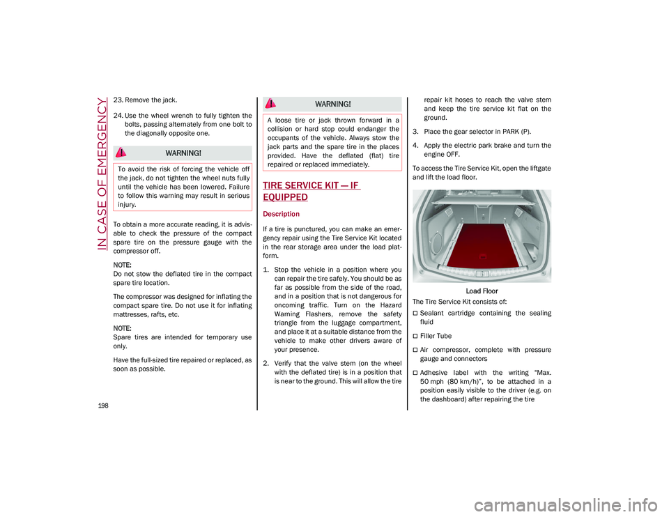
To access the Tire Service Kit, open the liftgate
and lift the load floor.
Load Floor
The Tire Service Kit consists of:
Sealant cartridge containing the sealing
fluid
Filler Tube
Air compressor, complete with pressure
gauge and connectors
Adhesive label with the writing "Max.
50 mph (80 km/h)”, to be attached in a
position easily visible to the driver (e.g. on
the dashboard) after repairing the tire
WARNING!
To avoid the risk of forcing the vehicle off
the jack, do not tighten the wheel nuts fully
until the vehicle has been lowered. Failure
to follow this warning may result in serious
injury.
WARNING!
A loose tire or jack thrown forward in a
collision or hard stop could endanger the
occupants of the vehicle. Always stow the
jack parts and the spare tire in the places
provided. Have the deflated (flat) tire
repaired or replaced immediately.
21_GU_OM_EN_USC_t.book Page 198
Page 243 of 280
241
Recommended Cold Tire Inflation Pressures
For vehicle speeds below 100 mph (160 km/h),
recommended cold tire inflation pressures are
listed on the Tire And Loading Information
Placard located on driver’s side B-pillar or the
rear edge of the driver's side door.
When driving at speeds 100 mph (160 km/h)
and above, increased tire pressures and
reduced vehicle loading are required for
high-speed vehicle operation.For driving speeds above 100 mph (160 km/h)
recommended cold tire inflation pressures are
listed below under "High Speed Tire Inflation
Pressure". Vehicle loading condition must not
exceed 688 lbs. (312 kg) (driver + three
passengers + 88 lbs. (40kg) luggage).
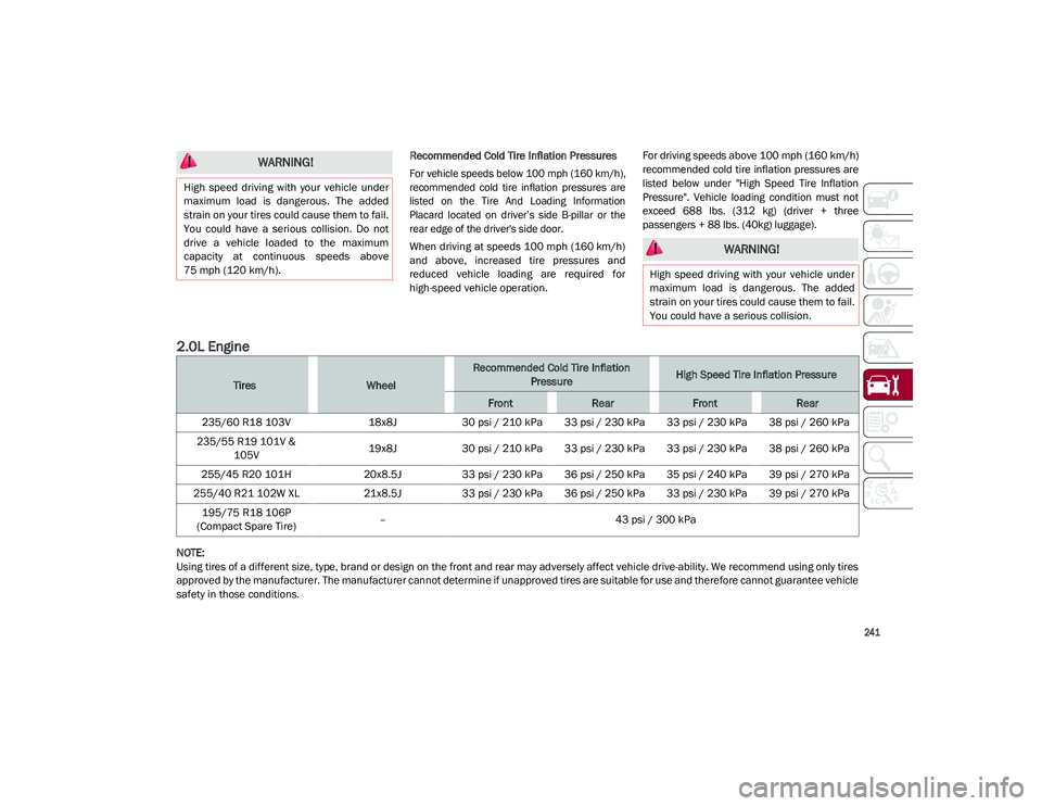
2.0L Engine
NOTE:
Using tires of a different size, type, brand or design on the front and rear may adversely affect vehicle drive-ability. We recommend using only tires
approved by the manufacturer. The manufacturer cannot determine if unapproved tires are suitable for use and therefore cannot guarantee vehicle
safety in those conditions.
WARNING!
High speed driving with your vehicle under
maximum load is dangerous. The added
strain on your tires could cause them to fail.
You could have a serious collision. Do not
drive a vehicle loaded to the maximum
capacity at continuous speeds above
75 mph (120 km/h).
WARNING!
High speed driving with your vehicle under
maximum load is dangerous. The added
strain on your tires could cause them to fail.
You could have a serious collision.
TiresWheel
Recommended Cold Tire Inflation PressureHigh Speed Tire Inflation Pressure
FrontRearFrontRear
235/60 R18 103V 18x8J30 psi / 210 kPa 33 psi / 230 kPa 33 psi / 230 kPa 38 psi / 260 kPa
235/55 R19 101V & 105V 19x8J
30 psi / 210 kPa 33 psi / 230 kPa 33 psi / 230 kPa 38 psi / 260 kPa
255/45 R20 101H 20x8.5J33 psi / 230 kPa 36 psi / 250 kPa 35 psi / 240 kPa 39 psi / 270 kPa
255/40 R21 102W XL 21x8.5J33 psi / 230 kPa 36 psi / 250 kPa 33 psi / 230 kPa 39 psi / 270 kPa
195/75 R18 106P
(Compact Spare Tire) –
43 psi / 300 kPa
21_GU_OM_EN_USC_t.book Page 241