2021 ALFA ROMEO STELVIO towing
[x] Cancel search: towingPage 13 of 280
11
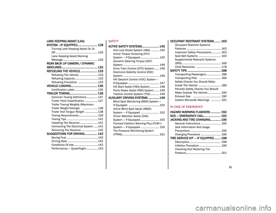
LANE KEEPING ASSIST (LKA)
SYSTEM —IF EQUIPPED......................... 128
Turning Lane Keeping Assist On Or
Off ......................................................... 129 Lane Keeping Assist Warning
Message ...............................................129
REAR BACK UP CAMERA / DYNAMIC
GRIDLINES ............................................. 132 REFUELING THE VEHICLE ..................... 133
Refueling The Vehicle ..........................133
Refueling Capacity ............................... 133
Refueling Procedure ...........................133
VEHICLE LOADING ................................. 135
Certification Label................................ 135
TRAILER TOWING................................... 136
Common Towing Definitions ...............137
Trailer Hitch Classification .................. 137
Trailer Towing Weights (Maximum
Trailer Weight Ratings) .....................138 Trailer And Tongue Weight ................. 138
Towing Requirements..........................139
Towing Tips ..........................................141
Installing The Receiver ........................ 141
Connecting The Electrical System ......141
Removing The Receiver ....................... 142
SUGGESTIONS FOR DRIVING................ 142
Saving Fuel ...........................................142
Driving Style .........................................142
Conditions Of Use ................................ 142
Performance — Quadrifoglio ...............143
SAFETY
ACTIVE SAFETY SYSTEMS...................... 145
Anti-Lock Brake System (ABS) ........... 145
Active Torque Vectoring (ATV)
System — If Equipped .......................... 145 Dynamic Steering Torque (DST)
System ................................................. 146 Drive Train Control (DTC) System ....... 146
Electronic Stability Control (ESC)
System ................................................. 146 Hill Descent Control (HDC) System —
If Equipped ........................................... 147 Hill Start Assist (HSA) System ............. 148
Panic Brake Assist (PBA) System ....... 149
Traction Control System (TCS) ............ 149
AUXILIARY DRIVING SYSTEMS .............. 149
Blind Spot Monitoring (BSM) System —
If Equipped ......................................... 150 Active Blind Spot Assist (ABSA)
System — If Equipped ......................... 152 Driver Attention Assist (DAA)
System — If Equipped .......................... 155 Forward Collision Warning Plus (FCW+)
System — If Equipped ......................... 156 Tire Pressure Monitoring System
(TPMS) .................................................. 161
OCCUPANT RESTRAINT SYSTEMS ........ 163
Occupant Restraint Systems
Features .............................................. 163 Important Safety Precautions ............ 163
Seat Belt Systems .............................. 164
Supplemental Restraint Systems
(SRS) .................................................... 169 Child Restraints ................................. 178
SAFETY TIPS .......................................... 188
Transporting Passengers .................... 188
Transporting Pets ............................. 189
Safety Checks You Should Make
Inside The Vehicle .............................. 189 Periodic Safety Checks You Should
Make Outside The Vehicle .................. 190 Exhaust Gas ..................................... 190
Carbon Monoxide Warnings ............. 191
IN CASE OF EMERGENCY
HAZARD WARNING FLASHERS ............. 192
SOS — EMERGENCY CALL ..................... 192
JACKING AND TIRE CHANGING............. 195
General Instructions ........................... 195
Jack Information And Usage
Precautions ......................................... 195 Changing Procedure ........................... 196
TIRE SERVICE KIT — IF EQUIPPED ........ 198
Description .......................................... 198
Inflation Procedure ............................. 199
Checking And Restoring Tire
Pressure............................................... 201
21_GU_OM_EN_USC_t.book Page 11
Page 14 of 280

12
JUMP STARTING .................................... 201
Remote Battery Connection Posts......202
Jump Starting Procedure.....................203
Bump Starting ..................................204
ENGINE OVERHEATING ......................... 204 MANUAL PARK RELEASE ...................... 205TOWING A DISABLED VEHICLE ............. 205
Four-Wheel Drive (AWD) Models .........206
TOW EYES .............................................. 206
ENHANCED ACCIDENT RESPONSE
SYSTEM (EARS) ..................................... 207EVENT DATA RECORDER (EDR) ............ 207
SERVICING AND MAINTENANCE
SCHEDULED SERVICING ....................... 208
Periodic Checks ...................................208
Heavy Usage Of The Vehicle ...............208
Maintenance Plan (2.0L Engine) ........209
Maintenance Plan (2.9L Engine) ........212
ENGINE COMPARTMENT....................... 214
Checking Levels — 2.0L Engine .......... 214
Checking Levels — 2.9L Engine .......... 215
Engine Oil ............................................. 215
Engine Coolant Fluid............................216
Washer Fluid For Windshield/
Headlights ............................................ 217 Brake Fluid ...........................................217
Automatic Transmission Activation
System Oil ............................................ 217 Useful Advice For Extending The Life Of
Your Battery..........................................217 Battery ..................................................217
Pressure Washing ................................ 218
BATTERY RECHARGING ......................... 218
Important Notes .................................. 218
VEHICLE MAINTENANCE ........................ 219
Engine Oil ............................................. 219
Engine Oil Filter ................................... 220
Engine Air Cleaner Filter ..................... 220
Air Conditioning System
Maintenance........................................ 220 Lubricating Moving Parts Of The
Bodywork ............................................. 220 Windshield Wiper................................. 221
Exhaust System ................................... 222
Cooling System .................................... 223
Braking System.................................... 224
Automatic Transmission ..................... 225
Replacing The Battery ......................... 225
Fuses .................................................... 225
Bulb Replacement ............................... 229
TIRES ...................................................... 233
Tire Safety Information .................... 233
Tires — General Information .............. 239
Spare Tires — If Equipped .................. 244
Wheel And Wheel Trim Care ............ 245
Tire Types ............................................. 246
Tire Chains and Traction Devices ....... 247
Tire Rotation Recommendations........ 247
DEPARTMENT OF TRANSPORTATION
UNIFORM TIRE QUALITY GRADES ......... 248
Treadwear ............................................ 248
Traction Grades ................................... 248
Temperature Grades ........................... 248
STORING THE VEHICLE ......................... 249 BODYWORK ........................................... 249
Protection Against Atmospheric
Agents .................................................. 249 Corrosion Warranty ............................. 250
Preserving The Bodywork .................. 250
INTERIORS ............................................. 251
Seats And Fabric Parts ....................... 251
Leather Seats ...................................... 251
Plastic And Coated Parts .................... 251
Alcantara Parts — If Equipped ............ 251
Genuine Leather Parts........................ 251
Carbon Fiber Parts .............................. 252
TECHNICAL SPECIFICATIONS
VEHICLE IDENTIFICATION
NUMBER (VIN) ....................................... 253
Vehicle Identification Number............ 253
Vehicle Identification Number
(VIN) Plate ............................................ 253
ENGINE .................................................. 254
POWER SUPPLY ..................................... 255 TRANSMISSION ..................................... 255BRAKES.................................................. 255
SUSPENSION ......................................... 256
STEERING .............................................. 256
DIMENSIONS ......................................... 257
Luggage Compartment Volume ......... 259
WEIGHTS ................................................ 259
21_GU_OM_EN_USC_t.book Page 12
Page 97 of 280
95
REVERSE (R)
Select this mode only with the vehicle at a
standstill.NEUTRAL (N)
Use this range when the vehicle is standing for
prolonged periods with the engine running.
The engine may be started in this range. Apply
the EPB and shift the transmission into PARK
(P) if you must leave the vehicle.
DRIVE (D)
Use this mode in normal driving conditions.
Shifting from DRIVE (D) to PARK (P) or REVERSE
(R) modes must take place only after releasing the
accelerator pedal, with vehicle at a standstill and
brake pedal pressed.
This mode ensures automatic engagement of the
most suitable gears for driving needs and
maximum fuel economy in terms of consumption.
In this position, the transmission shifts the gears
automatically, selecting the most suitable for
forward driving among those available as you go.
In this way the vehicle's optimal driving charac
-
teristics are provided for all conditions.
AutoStick
In the case of frequent shifting (e.g. for sport
driving, when the vehicle is driven with a heavy
load, on slopes, when towing heavy trailers), it is
recommended to use the AutoStick (sequential
shifting) mode to select and keep a lower fixed
ratio.
In these conditions, the use of a lower gear
improves vehicle performance and prevents over
-
heating.
It is possible to shift from DRIVE (D) mode to Auto -
Stick mode regardless of vehicle speed.
Activation
Starting from DRIVE (D) mode, to activate the
sequential drive mode, move the gear selector to
the left (– and + indication of the trim). The gear
engaged will be shown on the display.
Shifting is made by moving the gear selector
forward, toward symbol – or backward, toward
symbol +.
Steering Column Mounted Shift Paddles — If
Equipped
The gear can be manually shifted also by using
the paddles behind the steering wheel, pull
the right paddle (+) toward the steering wheel
and release it to engage a higher gear,
perform the same operation with the left
paddle (-) to engage a lower gear.
Never leave children alone in a vehicle, or
with access to an unlocked vehicle.
Allowing children to be in a vehicle unat -
tended is dangerous for a number of
reasons. A child or others could be seri -
ously or fatally injured. Children should be
warned not to touch the park brake, brake
pedal or the transmission gear selector.
Do not leave the key fob in or near the
vehicle (or in a location accessible to chil -
dren), and do not leave the ignition in the
ACC mode. A child could operate power
windows, other controls, or move the
vehicle.
CAUTION!
Before moving the transmission gear
selector out of PARK, you must push the
ignition button to cycle from OFF mode to
the ACC mode, and also press the brake
pedal. Otherwise, damage to the gear
selector could result.
DO NOT race the engine when shifting
from PARK or NEUTRAL into another gear
range, as this can damage the drivetrain.
WARNING! (Continued)
WARNING!
Do not coast in NEUTRAL and never turn off
the ignition to coast down a hill. These are
unsafe practices that limit your response to
changing traffic or road conditions. You
might lose control of the vehicle and have a
collision.
21_GU_OM_EN_USC_t.book Page 95
Page 113 of 280
111
Overtake Aid
When driving with ACC engaged and following
a vehicle at a speed greater than 45 mph
(70 km/h), the system will provide an addi-
tional acceleration up to the ACC set speed to
assist in passing the vehicle. This additional
acceleration is triggered when the driver
utilizes the left turn signal and will only be
active when passing on the left hand side.
The system detects the direction of traffic auto -
matically when the vehicle passes from left
hand traffic to right hand traffic. In this case,
the overtaking assist function is only active
when the reference vehicle is overtaken on the
right. The additional acceleration is deactivated
when the driver uses the right direction indi -
cator and returns to the original lane.
“Stop And Go” Function
The “Stop and Go” operating strategy allows
you to maintain a safe distance from the
vehicle ahead until the vehicle has completely
stopped.
In the event that the ACC system brings your
vehicle to a standstill while following the
vehicle in front, if the vehicle in front starts moving within two seconds of your vehicle
coming to a standstill, your vehicle will resume
motion without the need for any driver action.
If the vehicle in front does not start moving
within two seconds of your vehicle coming to a
standstill, the driver will have to push the RES/
SET switch upward to restart.
Deactivation
The system is deactivated and the set speed is
canceled if:
The on/off button is pushed (when the
system is on or paused).
The ignition is placed in the OFF position
RACE mode is activated (Quadrifoglio
models)
The system is canceled (the set speed and
distance are stored):
When the system is paused
Úpage 108
When the conditions shown in the “Activating
Adaptive Cruise Control (ACC)” section occur
Úpage 108
Limited Operation Warning
If the dedicated message is shown on the
display, a condition limiting the Adaptive
Cruise Control operation may have occurred.
This could be due to an obstruction of the
vehicle’s sensor or camera. It could also be
due to a fault in the system. If an obstruction
is detected, clean the area of the windshield
opposite the interior rearview mirror, where
the camera is located, as well as the area of
the front fascia/bumper where the sensor is
located. Then check that the message has
disappeared.
When the conditions limiting the system func -
tions end, normal operation will resume.
Should the fault persist, contact an authorized
dealer.
Precautions While Driving With ACC
In certain driving situations, ACC may have
detection issues. In these cases, ACC may
brake late or unexpectedly. The driver needs
to stay alert and may need to intervene. The
following are examples of these types of situa -
tions:
Towing A Trailer
Towing a trailer is not advised when using ACC.
Offset Driving
ACC may not detect a vehicle in the same lane
that is offset from your direct line of travel, or
a vehicle merging in from a side lane. There
may not be sufficient distance to the vehicle
The driver is fully responsible for holding a
safe distance from the vehicle ahead
respecting the highway code in force in
the respective country.
WARNING! (Continued)
WARNING!
When the ACC system is resumed, the
driver must ensure that there are no
pedestrians, vehicles or objects in the path
of the vehicle. Failure to follow these
warnings can result in a collision and death
or serious personal injury.
21_GU_OM_EN_USC_t.book Page 111
Page 127 of 280
125
Pushing the button a second time will turn the
system back on, and the indicator light will
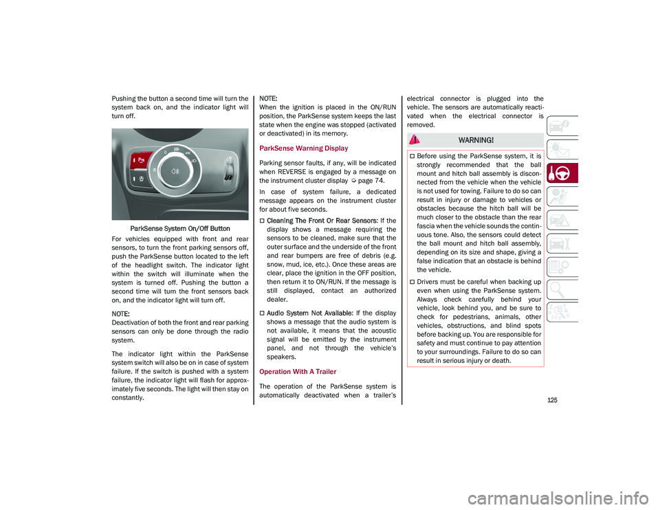
turn off.ParkSense System On/Off Button
For vehicles equipped with front and rear
sensors, to turn the front parking sensors off,
push the ParkSense button located to the left
of the headlight switch. The indicator light
within the switch will illuminate when the
system is turned off. Pushing the button a
second time will turn the front sensors back
on, and the indicator light will turn off.
NOTE:
Deactivation of both the front and rear parking
sensors can only be done through the radio
system.
The indicator light within the ParkSense
system switch will also be on in case of system
failure. If the switch is pushed with a system
failure, the indicator light will flash for approx -
imately five seconds. The light will then stay on
constantly.
NOTE:
When the ignition is placed in the ON/RUN
position, the ParkSense system keeps the last
state when the engine was stopped (activated
or deactivated) in its memory.
ParkSense Warning Display
Parking sensor faults, if any, will be indicated
when REVERSE is engaged by a message on
the instrument cluster display
Ú
page 74.
In case of system failure, a dedicated
message appears on the instrument cluster
for about five seconds.
Cleaning The Front Or Rear Sensors : If the
display shows a message requiring the
sensors to be cleaned, make sure that the
outer surface and the underside of the front
and rear bumpers are free of debris (e.g.
snow, mud, ice, etc.). Once these areas are
clear, place the ignition in the OFF position,
then return it to ON/RUN. If the message is
still displayed, contact an authorized
dealer.
Audio System Not Available : If the display
shows a message that the audio system is
not available, it means that the acoustic
signal will be emitted by the instrument
panel, and not through the vehicle’s
speakers.
Operation With A Trailer
The operation of the ParkSense system is
automatically deactivated when a trailer’s electrical connector is plugged into the
vehicle. The sensors are automatically reacti
-
vated when the electrical connector is
removed.
WARNING!
Before using the ParkSense system, it is
strongly recommended that the ball
mount and hitch ball assembly is discon -
nected from the vehicle when the vehicle
is not used for towing. Failure to do so can
result in injury or damage to vehicles or
obstacles because the hitch ball will be
much closer to the obstacle than the rear
fascia when the vehicle sounds the contin -
uous tone. Also, the sensors could detect
the ball mount and hitch ball assembly,
depending on its size and shape, giving a
false indication that an obstacle is behind
the vehicle.
Drivers must be careful when backing up
even when using the ParkSense system.
Always check carefully behind your
vehicle, look behind you, and be sure to
check for pedestrians, animals, other
vehicles, obstructions, and blind spots
before backing up. You are responsible for
safety and must continue to pay attention
to your surroundings. Failure to do so can
result in serious injury or death.
21_GU_OM_EN_USC_t.book Page 125
Page 128 of 280
STARTING AND OPERATING
126
(Continued)
ParkSense System Usage Precautions
NOTE:
Some conditions may influence the perfor-
mance of the ParkSense system:
Reduced sensor sensitivity could be due to
the presence of ice, snow, mud, or thick
paint on the surface of the sensor.
The sensors may detect a false obstacle
(echo interference) due to mechanical inter -
ference, for example when washing the
vehicle or in extreme weather.
The signals sent by the sensors can be
altered by the presence of ultrasonic
systems (e.g. pneumatic brake systems of
trucks or pneumatic drills) near the vehicle.
System performance can be influenced by
the position of the sensors. For example,
due to a change in the ride setting (caused
by wear to the shock absorbers or suspen -
sion), by changing tires, overloading the
vehicle or operations that require the
vehicle to be lowered.
Be sure not to place bumper stickers or
other adhesives over the sensors as this will
affect system performance.
The presence of a trailer hitch without a
trailer. This may interfere with the operation
of the parking sensors. Before using the
ParkSense system, it is recommended to remove or close the trailer hitch assembly
when the vehicle is not being used for
towing.
LANE DEPARTURE WARNING
(LDW) SYSTEM
Lane Departure Warning Operation
The Lane Departure Warning system uses a
forward looking camera located on the wind
-
shield to detect lane markings and measure
vehicle position within the lane boundaries.
When one or both lane limits are detected and
the vehicle passes over one without an acti -
vated turn signal, the system emits a visual as
well as an acoustic signal.
If the vehicle continues to go beyond the line
of the lane without any intervention from the
driver, the surpassed line will light up on the
display (left or right) to urge the driver to bring
the vehicle back into the limits of the lane.
CAUTION!
Projecting loads on the roof of the vehicle
may interfere with the correct operation of
the camera. Before starting, make sure
the load is correctly positioned in order
not to cover the camera operating range.
Do not cover the operating range of the
camera with stickers or other objects.
Do not tamper with nor operate on the
camera. Do not close the openings in the
aesthetic cover located under the interior
rearview mirror. In the event of a failure of
the camera, contact your authorized
dealer.
The camera may have limited or absent
operation due to weather conditions such
as: heavy rain, hail, thick fog, heavy snow,
formation of ice layers on the windshield.
Camera operation may also be compro -
mised by the presence of dust, condensa -
tion, dirt or ice on the windshield, by traffic
conditions (e.g. vehicles that are driving
not aligned with yours, vehicle driving in a
transverse or opposite way on the same
lane, bend with a small radius of curva -
ture), by road surface conditions and by
driving conditions (e.g. off-road driving).
Make sure the windshield is always clean.
Use specific detergents and clean cloths
to avoid scratching the windshield. The
camera operation may also be limited or
absent in some driving, traffic and road
surface conditions.
If the windshield must be replaced due to
scratches, chipping or breakage, contact
exclusively an authorized dealer. Do not
replace the windshield on your own. It is
advisable to replace the windshield if it is
damaged in the area of the camera.
CAUTION! (Continued)
21_GU_OM_EN_USC_t.book Page 126
Page 138 of 280
STARTING AND OPERATING
136
Gross Vehicle Weight Rating (GVWR)
The GVWR is the total permissible weight of
your vehicle including driver, passengers,
vehicle, options and cargo. The label also
specifies maximum capacities of front and
rear axle systems (GAWR). Total load must be
limited so GVWR and front and rear GAWR are
not exceeded.
Payload
The payload of a vehicle is defined as the
allowable load weight a truck can carry,
including the weight of the driver, all passen-
gers, options and cargo.
Gross Axle Weight Rating (GAWR)
The GAWR is the maximum permissible load
on the front and rear axles. The load must be
distributed in the cargo area so that the GAWR
of each axle is not exceeded.
Each axle GAWR is determined by the compo -
nents in the system with the lowest load
carrying capacity (axle, springs, tires or
wheels). Heavier axles or suspension compo -
nents sometimes specified by purchasers for
increased durability do not necessarily
increase the vehicle's GVWR.
Tire Size
The tire size on the Vehicle Certification Label
represents the actual tire size on your vehicle.
Replacement tires must be equal to the load
capacity of this tire size.
Rim Size
This is the rim size that is appropriate for the
tire size listed.
Inflation Pressure
This is the cold tire inflation pressure for your
vehicle for all loading conditions up to full
GAWR.
Curb Weight
The curb weight of a vehicle is defined as the
total weight of the vehicle with all fluids,
including vehicle fuel, at full capacity condi -
tions, and with no occupants or cargo loaded
into the vehicle. The front and rear curb weight
values are determined by weighing your
vehicle on a commercial scale before any
occupants or cargo are added.
Loading
The actual total weight and the weight of the
front and rear of your vehicle at the ground can
best be determined by weighing it when it is
loaded and ready for operation.
The entire vehicle should first be weighed on a
commercial scale to ensure that the GVWR
has not been exceeded. The weight on the
front and rear of the vehicle should then be
determined separately to be sure that the load
is properly distributed over the front and rear
axle. Weighing the vehicle may show that the
GAWR of either the front or rear axles has
been exceeded but the total load is within the specified GVWR. If so, weight must be shifted
from front to rear or rear to front as appro
-
priate until the specified weight limitations are
met. Store the heavier items down low and be
sure that the weight is distributed equally.
Stow all loose items securely before driving.
Improper weight distributions can have an
adverse effect on the way your vehicle steers
and handles and the way the brakes operate.
TRAILER TOWING
In this section you will find safety tips and
information on limits to the type of towing you
can reasonably do with your vehicle. Before
towing a trailer, carefully review this informa -
tion to tow your load as efficiently and safely
as possible.
To maintain the New Vehicle Limited Warranty
coverage, follow the requirements and recom -
mendations in this manual concerning vehi -
cles used for trailer towing.
CAUTION!
Do not load your vehicle any heavier than
the GVWR or the maximum front and rear
GAWR. If you do, parts on your vehicle can
break, or it can change the way your vehicle
handles. This could cause you to lose
control. Also overloading can shorten the
life of your vehicle.
21_GU_OM_EN_USC_t.book Page 136
Page 139 of 280
137
Common Towing Definitions
The following trailer towing related definitions
will assist you in understanding the following
information:
Gross Vehicle Weight Rating (GVWR)
The GVWR is the total allowable weight of your
vehicle. This includes driver, passengers,
cargo and tongue weight. The total load must
be limited so that you do not exceed the GVWR
Ú
page 135.
Gross Trailer Weight (GTW)
The GTW is the weight of the trailer plus the
weight of all cargo, consumables, and equip -
ment (permanent or temporary) loaded in or
on the trailer in its "loaded and ready for oper -
ation" condition.
The recommended way to measure GTW is to
put your fully loaded trailer on a vehicle scale.
The entire weight of the trailer must be
supported by the scale.
Gross Combination Weight Rating (GCWR)
The GCWR is the total allowable weight of your
vehicle and trailer when weighed in combination.
Gross Axle Weight Rating (GAWR)
The GAWR is the maximum capacity of the
front and rear axles. Distribute the load over
the front and rear axles evenly. Make sure that
you do not exceed either front or rear GAWR
Ú
page 135.
Tongue Weight (TW)
The tongue weight is the downward force
exerted on the hitch ball by the trailer. You
must consider this as part of the load on your
vehicle.
Trailer Frontal Area
The frontal area is the maximum height multi -
plied by the maximum width of the front of a
trailer.
Weight-Carrying Hitch
A weight-carrying hitch supports the trailer
tongue weight, just as if it were luggage
located at a hitch ball or some other
connecting point of the vehicle. These kinds of
hitches are the most popular on the market
today and they are commonly used to tow
small and medium sized trailers.
Weight-Distributing Hitch
A weight-distributing system works by applying
leverage through spring (load) bars. They are
typically used for heavier loads to distribute
trailer tongue weight to the tow vehicle's front axle and the trailer axle(s). When used in
accordance with the manufacturer's direc
-
tions, it provides for a more level ride, offering
more consistent steering and brake control
thereby enhancing towing safety. The addition
of a friction/hydraulic sway control also
dampens sway caused by traffic and cross -
winds and contributes positively to tow vehicle
and trailer stability. Trailer Sway Control and a
weight distributing (load equalizing) hitch are
recommended for heavier Tongue Weights
(TW) and may be required depending on
vehicle and trailer configuration/loading to
comply with Gross Axle Weight Rating (GAWR)
requirements.
Trailer Hitch Classification
The following chart provides the industry stan -
dard for the maximum trailer weight a given
trailer hitch class can tow and should be used
to assist you in selecting the correct trailer
hitch for your intended towing condition.
WARNING!
It is important that you do not exceed the
maximum front or rear GAWR. A dangerous
driving condition can result if either rating is
exceeded. You could lose control of the
vehicle and have a collision.
WARNING!
An improperly adjusted Weight Distrib -
uting Hitch system may reduce handling,
stability, braking performance, and could
result in a collision.
Weight Distributing Systems may not be
compatible with Surge Brake Couplers.
Consult with the hitch and trailer manu -
facturer or a reputable Recreational
Vehicle dealer for additional information.
21_GU_OM_EN_USC_t.book Page 137