2021 ALFA ROMEO STELVIO wheel size
[x] Cancel search: wheel sizePage 79 of 280
77
also reduces fuel efficiency and tire tread life,
and may affect the vehicle’s handling and
stopping ability.
Please note that the TPMS is not a substitute
for proper tire maintenance, and it is the
driver’s responsibility to maintain correct tire
pressure, even if under inflation has not
reached the level to trigger illumination of the
TPMS low tire pressure telltale.
Your vehicle has also been equipped with a
TPMS malfunction indicator to indicate when
the system is not operating properly. The
TPMS malfunction indicator is combined with
the low tire pressure telltale. When the system
detects a malfunction, the telltale will flash for
approximately one minute and then remain
continuously illuminated. This sequence will
continue upon subsequent vehicle start-ups
as long as the malfunction exists. When the
malfunction indicator is illuminated, the
system may not be able to detect or signal low
tire pressure as intended. TPMS malfunctions
may occur for a variety of reasons, including
the installation of replacement or alternate
tires or wheels on the vehicle that prevent the
TPMS from functioning properly. Always check
the TPMS malfunction telltale after replacing
one or more tires or wheels on your vehicle to
ensure that the replacement or alternate tires
and wheels allow the TPMS to continue to
function properly.
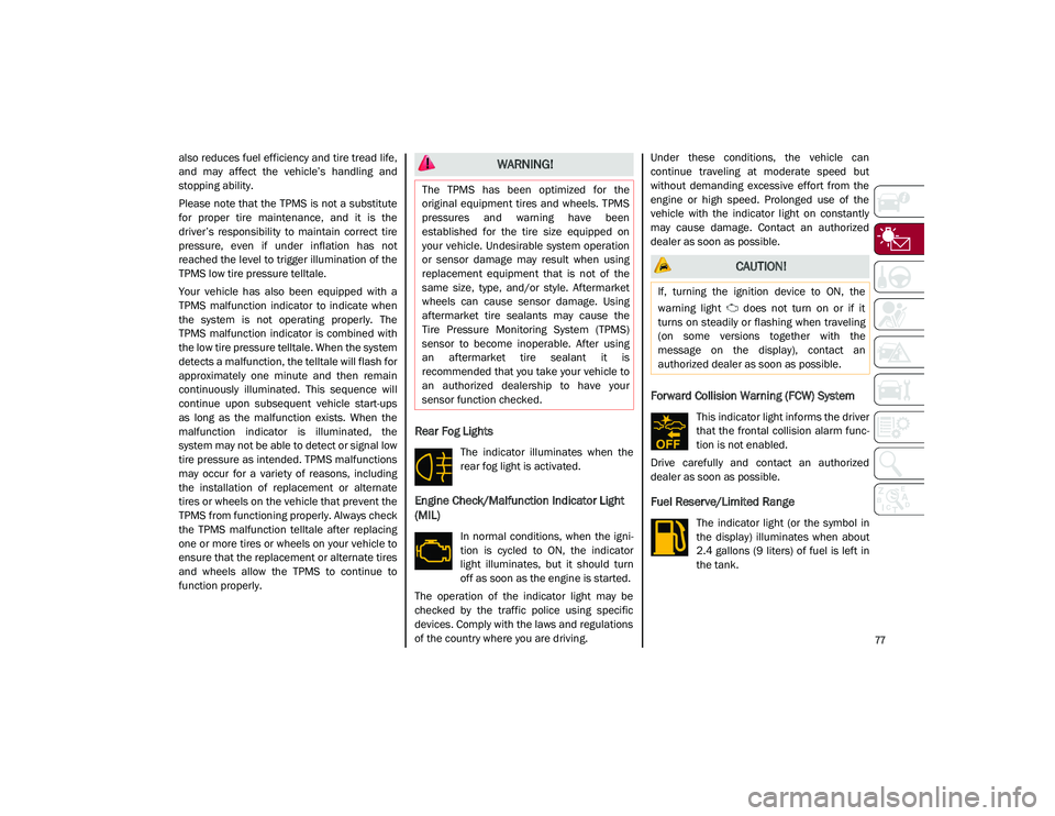
Rear Fog Lights
The indicator illuminates when the
rear fog light is activated.
Engine Check/Malfunction Indicator Light
(MIL)
In normal conditions, when the igni-
tion is cycled to ON, the indicator
light illuminates, but it should turn
off as soon as the engine is started.
The operation of the indicator light may be
checked by the traffic police using specific
devices. Comply with the laws and regulations
of the country where you are driving. Under these conditions, the vehicle can
continue traveling at moderate speed but
without demanding excessive effort from the
engine or high speed. Prolonged use of the
vehicle with the indicator light on constantly
may cause damage. Contact an authorized
dealer as soon as possible.
Forward Collision Warning (FCW) System
This indicator light informs the driver
that the frontal collision alarm func
-
tion is not enabled.
Drive carefully and contact an authorized
dealer as soon as possible.
Fuel Reserve/Limited Range
The indicator light (or the symbol in
the display) illuminates when about
2.4 gallons (9 liters) of fuel is left in
the tank.
WARNING!
The TPMS has been optimized for the
original equipment tires and wheels. TPMS
pressures and warning have been
established for the tire size equipped on
your vehicle. Undesirable system operation
or sensor damage may result when using
replacement equipment that is not of the
same size, type, and/or style. Aftermarket
wheels can cause sensor damage. Using
aftermarket tire sealants may cause the
Tire Pressure Monitoring System (TPMS)
sensor to become inoperable. After using
an aftermarket tire sealant it is
recommended that you take your vehicle to
an authorized dealership to have your
sensor function checked.
CAUTION!
If, turning the ignition device to ON, the
warning light does not turn on or if it
turns on steadily or flashing when traveling
(on some versions together with the
message on the display), contact an
authorized dealer as soon as possible.
21_GU_OM_EN_USC_t.book Page 77
Page 138 of 280
STARTING AND OPERATING
136
Gross Vehicle Weight Rating (GVWR)
The GVWR is the total permissible weight of
your vehicle including driver, passengers,
vehicle, options and cargo. The label also
specifies maximum capacities of front and
rear axle systems (GAWR). Total load must be
limited so GVWR and front and rear GAWR are
not exceeded.
Payload
The payload of a vehicle is defined as the
allowable load weight a truck can carry,
including the weight of the driver, all passen-
gers, options and cargo.
Gross Axle Weight Rating (GAWR)
The GAWR is the maximum permissible load
on the front and rear axles. The load must be
distributed in the cargo area so that the GAWR
of each axle is not exceeded.
Each axle GAWR is determined by the compo -
nents in the system with the lowest load
carrying capacity (axle, springs, tires or
wheels). Heavier axles or suspension compo -
nents sometimes specified by purchasers for
increased durability do not necessarily
increase the vehicle's GVWR.
Tire Size
The tire size on the Vehicle Certification Label
represents the actual tire size on your vehicle.
Replacement tires must be equal to the load
capacity of this tire size.
Rim Size
This is the rim size that is appropriate for the
tire size listed.
Inflation Pressure
This is the cold tire inflation pressure for your
vehicle for all loading conditions up to full
GAWR.
Curb Weight
The curb weight of a vehicle is defined as the
total weight of the vehicle with all fluids,
including vehicle fuel, at full capacity condi -
tions, and with no occupants or cargo loaded
into the vehicle. The front and rear curb weight
values are determined by weighing your
vehicle on a commercial scale before any
occupants or cargo are added.
Loading
The actual total weight and the weight of the
front and rear of your vehicle at the ground can
best be determined by weighing it when it is
loaded and ready for operation.
The entire vehicle should first be weighed on a
commercial scale to ensure that the GVWR
has not been exceeded. The weight on the
front and rear of the vehicle should then be
determined separately to be sure that the load
is properly distributed over the front and rear
axle. Weighing the vehicle may show that the
GAWR of either the front or rear axles has
been exceeded but the total load is within the specified GVWR. If so, weight must be shifted
from front to rear or rear to front as appro
-
priate until the specified weight limitations are
met. Store the heavier items down low and be
sure that the weight is distributed equally.
Stow all loose items securely before driving.
Improper weight distributions can have an
adverse effect on the way your vehicle steers
and handles and the way the brakes operate.
TRAILER TOWING
In this section you will find safety tips and
information on limits to the type of towing you
can reasonably do with your vehicle. Before
towing a trailer, carefully review this informa -
tion to tow your load as efficiently and safely
as possible.
To maintain the New Vehicle Limited Warranty
coverage, follow the requirements and recom -
mendations in this manual concerning vehi -
cles used for trailer towing.
CAUTION!
Do not load your vehicle any heavier than
the GVWR or the maximum front and rear
GAWR. If you do, parts on your vehicle can
break, or it can change the way your vehicle
handles. This could cause you to lose
control. Also overloading can shorten the
life of your vehicle.
21_GU_OM_EN_USC_t.book Page 136
Page 141 of 280
139
(Continued)
Consider the following items when computing
the weight on the rear axle of the vehicle:
The tongue weight of the trailer.
The weight of any other type of cargo or
equipment put in or on your vehicle.
The weight of the driver and all passengers.
NOTE:
Remember that everything put into or on the
trailer adds to the load on your vehicle. Also,
additional factory-installed options or
dealer-installed options must be considered
as part of the total load on your vehicle. Refer
to the “Tire And Loading Information” placard
for the maximum combined weight of occu -
pants and cargo for your vehicle.
Towing Requirements
To promote proper break-in of your new
vehicle drivetrain components, the following
guidelines are recommended:
Towing Requirements — Tires
Do not attempt to tow a trailer while using a
compact spare tire.
Do not drive more than 50 mph (80 km/h)
when towing while using a full size spare
tire.
Proper tire inflation pressures are essential
to the safe and satisfactory operation of
your vehicle.
Check the trailer tires for proper tire infla -
tion pressures before trailer usage.
Check for signs of tire wear or visible tire
damage before towing a trailer.
Replacing tires with a higher load carrying
capacity will not increase the vehicle's
GVWR and GAWR limits.
For proper tire inflation procedures
Ú
page 233.
WARNING!
Improper towing can lead to a collision.
Follow these guidelines to make your trailer
towing as safe as possible:
Make certain that the load is secured in
the trailer and that it will not shift during
travel. When trailering cargo that is not
fully secured, dynamic load shifts can
occur that may be difficult for the driver to
control. You could lose control of your
vehicle and have a collision.
When hauling cargo, or towing a trailer, do
not overload your vehicle or trailer. Over -
loading can cause a loss of control, poor
performance, or damage to brakes, axle,
engine, transmission, steering, suspen -
sion, chassis structure, or tires.
Safety chains must always be used
between your vehicle and trailer. Always
connect the chains to the frame or hook
retainers of the vehicle hitch. Cross the
chains under the trailer tongue and allow
enough slack for turning corners.
Vehicles with trailers should not be parked
on a grade. When parking, apply the
parking brake on the tow vehicle. Put the
tow vehicle transmission in PARK. Always
block or "chock" the trailer wheels.
GCWR must not be exceeded.
Total weight must be distributed between
the tow vehicle and the trailer such that
the following four ratings are not
exceeded:
• GVWR
• GTW
• GAWR
• Tongue weight rating for the trailer
hitch utilized.
WARNING! (Continued) CAUTION!
Do not tow a trailer at all during the first
500 miles (805 km) the new vehicle is
driven. The engine, axle or other parts
could be damaged.
Then, during the first 500 miles (805 km)
that a trailer is towed, do not drive over
50 mph (80 km/h) and do not make
starts at full throttle. This helps the engine
and other parts of the vehicle wear in at
the heavier loads.
21_GU_OM_EN_USC_t.book Page 139
Page 149 of 280
147
Hill Descent Control (HDC) System — If
Equipped
The HDC function is an integral part of the
Electronic Stability Control (ESC) system,
keeping the vehicle at a constant speed while
descending a hill by actively controlling the
brakes.
HDC aims to create vehicle stability and safer
driving in various situations, including poor
grip conditions and steep descents.
The system has three different modes:
Off: the system is deactivated
Enabled: the system is enabled and ready to
intervene when the activation conditions
are met
Active: the system actively controls the
vehicle speed
Enabling The System
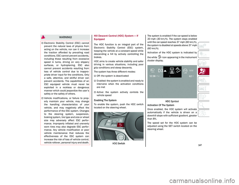
To enable the system, push the HDC switch
located on the steering wheel.
HDC Switch The system is enabled if the car speed is below
20 mph (30 km/h). The system stays enabled
until the car speed reaches 37 mph (60 km/h),
the system is disabled at speeds above 37 mph
(60 km/h).
Activation of the HDC system is indicated by
the white icon appearing in the instrument
cluster display.
HDC Symbol
Activation Of The System
Once enabled, the HDC system will activate
automatically if the vehicle is driven on a
downhill slope with sufficient gradient, greater
than 8%.
The speed set for the HDC system can be
adjusted using the SET switch located on the
steering wheel.
WARNING!
Electronic Stability Control (ESC) cannot
prevent the natural laws of physics from
acting on the vehicle, nor can it increase
the traction afforded by prevailing road
conditions. ESC cannot prevent accidents,
including those resulting from excessive
speed in turns, driving on very slippery
surfaces, or hydroplaning. ESC also
cannot prevent accidents resulting from
loss of vehicle control due to inappro -
priate driver input for the conditions. Only
a safe, attentive, and skillful driver can
prevent accidents. The capabilities of an
ESC equipped vehicle must never be
exploited in a reckless or dangerous
manner which could jeopardize the user’s
safety or the safety of others.
Vehicle modifications, or failure to prop -
erly maintain your vehicle, may change
the handling characteristics of your
vehicle, and may negatively affect the
performance of the ESC system. Changes
to the steering system, suspension,
braking system, tire type and size or wheel
size may adversely affect ESC perfor-
mance. Improperly inflated and unevenly
worn tires may also degrade ESC perfor -
mance. Any vehicle modification or poor
vehicle maintenance that reduces the
effectiveness of the ESC system can
increase the risk of loss of vehicle control,
vehicle rollover, personal injury and death.
21_GU_OM_EN_USC_t.book Page 147
Page 164 of 280
SAFETY
162
will turn off only after the tires are inflated to the
vehicle’s recommended cold placard pressure
value.Insufficient Tire Pressure Indication
If an insufficient pressure value is detected on
one or more tires, the warning light in the
instrument cluster will display alongside the
dedicated messages, the system will highlight
the tire or tires with insufficient pressure
graphically, and an acoustic signal will be
emitted.
In this case, stop the vehicle, check the infla
-
tion pressure of each tire, and inflate the
necessary tire or tires to the correct cold infla -
tion pressure value, shown on the display or in
the dedicated TPMS menu.
TPMS Temporarily Disabled:
TPMS Check Message
When a system fault is detected, the TPMS
Warning Light will flash on and off for 75 seconds,
and then remain on solid. The system fault will
also sound a chime. If the ignition is cycled, this
sequence will repeat, provided that the system
fault still exists. The TPMS Warning Light will turn
off when the fault condition no longer exists. A
system fault can occur due to any of the
following:
Jamming due to electronic devices or
driving next to facilities emitting the same
radio frequencies as the TPMS sensors.
Installing some form of aftermarket window
tinting that affects radio wave signals.
Packed snow or ice around the wheels or
wheel housings.
Using tire chains on the vehicle.
Using wheels/tires not equipped with TPMS
sensors.
After the punctured tire has been repaired
with the original tire sealant contained in the
Tire Kit, the previous condition must be
restored so that the warning light is off
during normal driving.
TPMS Deactivation
The TPMS can be deactivated by replacing all
four wheel and tire assemblies (road tires)
with wheel and tire assemblies that do not
have TPMS sensors, such as when installing
winter wheel and tire assemblies on your
vehicle.
To deactivate the TPMS, first replace all four
wheel and tire assemblies (road tires) with tires
not equipped with Tire Pressure Monitoring
System (TPMS) sensors. Then, drive the vehicle
for 20 minutes above 15 mph (24 km/h). The
TPMS will chime, the TPMS Warning Light will
flash on and off for 75 seconds and then
remain on. The instrument cluster will display
the “SERVICE TPM SYSTEM” message and then
display dashes (--) in place of the pressure
values.
Beginning with the next ignition switch cycle,
the TPMS will no longer chime or display the
“SERVICE TPM SYSTEM” message in the
instrument cluster. Instead, dashes (--) will
remain in place of the pressure values.
CAUTION!
The TPMS has been optimized for the orig -
inal equipment tires and wheels. TPMS
pressures and warning have been estab -
lished for the tire size equipped on your
vehicle. Undesirable system operation or
sensor damage may result when using
replacement equipment that is not of the
same size, type, and/or style. The TPMS
sensor is not designed for use on after -
market wheels and may contribute to a
poor overall system performance or
sensor damage. Customers are encour -
aged to use OEM wheels to assure proper
TPMS feature operation.
Using aftermarket tire sealants may cause
the Tire Pressure Monitoring System
(TPMS) sensor to become inoperable.
After using an aftermarket tire sealant it is
recommended that you take your vehicle
to an authorized dealer to have your
sensor function checked.
After inspecting or adjusting the tire pres -
sure always reinstall the valve stem cap.
This will prevent moisture and dirt from
entering the valve stem, which could
damage the TPMS sensor.
21_GU_OM_EN_USC_t.book Page 162
Page 174 of 280
SAFETY
172
damage by themselves are not good indicators
of whether or not an air bag should have
deployed.
Seat belts are necessary for your protection in
all collisions, and also are needed to help keep
you in position, away from an inflating air bag.
When the Occupant Restraint Controller (ORC)
detects a collision requiring the front air bags,
it signals the inflator units. A large quantity of
non-toxic gas is generated to inflate the front
air bags.
The steering wheel hub trim cover and the
upper passenger side of the instrument panel
separate and fold out of the way as the air
bags inflate to their full size. The front air bags
fully inflate in less time than it takes to blink
your eyes. The front air bags then quickly
deflate while helping to restrain the driver and
front passenger.
Knee Impact Bolsters
The Knee Impact Bolsters help protect the
knees of the driver and front passenger, and
position the front occupants for improved
interaction with the front air bags.
Supplemental Driver And Front Passenger
Knee Air Bags
This vehicle is equipped with a Supplemental
Driver Knee Air Bag mounted in the instrument
panel below the steering column and a
Supplemental Passenger Knee Air Bag
mounted in the instrument panel below the
glove compartment. The Supplemental Knee
Air Bags provide enhanced protection during a
frontal impact by working together with the
seat belts, pretensioners, and front air bags.
Supplemental Side Air Bags
Supplemental Seat-Mounted Side Air Bags
(SABs)
This vehicle is equipped with Supplemental
Seat-Mounted Side Air Bags (SABs).
Supplemental Seat-Mounted Side Air Bags
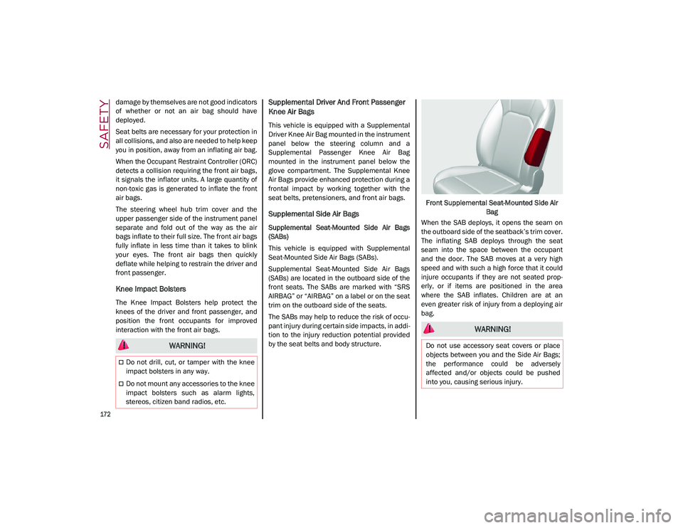
(SABs) are located in the outboard side of the
front seats. The SABs are marked with “SRS
AIRBAG” or “AIRBAG” on a label or on the seat
trim on the outboard side of the seats.
The SABs may help to reduce the risk of occu-
pant injury during certain side impacts, in addi-
tion to the injury reduction potential provided
by the seat belts and body structure. Front Supplemental Seat-Mounted Side Air
Bag
When the SAB deploys, it opens the seam on
the outboard side of the seatback’s trim cover.
The inflating SAB deploys through the seat
seam into the space between the occupant
and the door. The SAB moves at a very high
speed and with such a high force that it could
injure occupants if they are not seated prop -
erly, or if items are positioned in the area
where the SAB inflates. Children are at an
even greater risk of injury from a deploying air
bag.
WARNING!
Do not drill, cut, or tamper with the knee
impact bolsters in any way.
Do not mount any accessories to the knee
impact bolsters such as alarm lights,
stereos, citizen band radios, etc.
WARNING!
Do not use accessory seat covers or place
objects between you and the Side Air Bags;
the performance could be adversely
affected and/or objects could be pushed
into you, causing serious injury.
21_GU_OM_EN_USC_t.book Page 172
Page 176 of 280
SAFETY
174
(Continued)
compartment. The Side Air Bags may deploy
during angled or offset frontal collisions where
the front air bags deploy.
Side Air Bags are a supplement to the seat belt
restraint system. Side Air Bags deploy in less
time than it takes to blink your eyes.
NOTE:
Air bag covers may not be obvious in the inte-
rior trim, but they will open during air bag
deployment.
Rollover Events
Side Air Bags and seat belt pretensioners are
designed to activate in certain rollover events.
The Occupant Restraint Controller (ORC)
determines whether deployment in a partic -
ular rollover event is appropriate, based on the
severity and type of collision. Vehicle damage
by itself is not a good indicator of whether or
not Side Air Bags and seat belt pretensioners
should have deployed.
The Side Air Bags and seat belt pretensioners
will not deploy in all rollover events. The roll -
over sensing system determines if a rollover
event may be in progress and whether deploy -
ment is appropriate. In the event the vehicle
experiences a rollover or near rollover event, and deployment is appropriate, the rollover
sensing system will deploy the side air bags
and seat belt pretensioners on both sides of
the vehicle.
The SABICs may help reduce the risk of partial
or complete ejection of vehicle occupants
through side windows in certain rollover or
side impact events.
Air Bag System Components
NOTE:
The Occupant Restraint Controller (ORC) moni
-
tors the internal circuits and interconnecting
wiring associated with electrical Air Bag
System Components listed below:
Occupant Restraint Controller (ORC)
Air Bag Warning Light
Steering Wheel and Column
Instrument Panel
Knee Impact Bolsters
Driver and Front Passenger Air Bags
Seat Belt Buckle Switch
Supplemental Side Air Bags
Supplemental Knee Air Bags
Front and Side Impact Sensors
Seat Belt Pretensioners
Seat Track Position Sensors
WARNING!
Occupants, including children, who are up
against or very close to Side Air Bags can
be seriously injured or killed. Occupants,
including children, should never lean on or
sleep against the door, side windows, or
area where the side air bags inflate, even
if they are in an infant or child restraint.
Seat belts (and child restraints where appro -
priate) are necessary for your protection in
all collisions. They also help keep you in
position, away from an inflating Side Air Bag.
To get the best protection from the Side Air
Bags, occupants must wear their seat belts
properly and sit upright with their backs
against the seats. Children must be properly
restrained in a child restraint or booster seat
that is appropriate for the size of the child.
WARNING!
Side Air Bags need room to inflate. Do not
lean against the door or window. Sit
upright in the center of the seat.
Being too close to the Side Air Bags during
deployment could cause you to be
severely injured or killed.
Relying on the Side Air Bags alone could
lead to more severe injuries in a collision.
The Side Air Bags work with your seat belt
to restrain you properly. In some colli -
sions, Side Air Bags won’t deploy at all.
Always wear your seat belt even though
you have Side Air Bags.
WARNING! (Continued)
21_GU_OM_EN_USC_t.book Page 174
Page 200 of 280
IN CASE OF EMERGENCY
198
23. Remove the jack.
24. Use the wheel wrench to fully tighten thebolts, passing alternately from one bolt to
the diagonally opposite one.
To obtain a more accurate reading, it is advis -
able to check the pressure of the compact
spare tire on the pressure gauge with the
compressor off.
NOTE:
Do not stow the deflated tire in the compact
spare tire location.
The compressor was designed for inflating the
compact spare tire. Do not use it for inflating
mattresses, rafts, etc.
NOTE:
Spare tires are intended for temporary use
only.
Have the full-sized tire repaired or replaced, as
soon as possible.
TIRE SERVICE KIT — IF
EQUIPPED
Description
If a tire is punctured, you can make an emer -
gency repair using the Tire Service Kit located
in the rear storage area under the load plat -
form.
1. Stop the vehicle in a position where you can repair the tire safely. You should be as
far as possible from the side of the road,
and in a position that is not dangerous for
oncoming traffic. Turn on the Hazard
Warning Flashers, remove the safety
triangle from the luggage compartment,
and place it at a suitable distance from the
vehicle to make other drivers aware of
your presence.
2. Verify that the valve stem (on the wheel with the deflated tire) is in a position that
is near to the ground. This will allow the tire repair kit hoses to reach the valve stem
and keep the tire service kit flat on the
ground.
3. Place the gear selector in PARK (P).
4. Apply the electric park brake and turn the engine OFF.
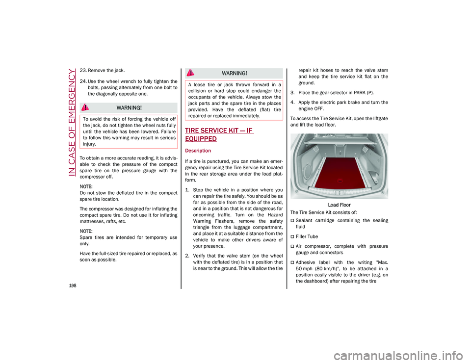
To access the Tire Service Kit, open the liftgate
and lift the load floor.
Load Floor
The Tire Service Kit consists of:
Sealant cartridge containing the sealing
fluid
Filler Tube
Air compressor, complete with pressure
gauge and connectors
Adhesive label with the writing "Max.
50 mph (80 km/h)”, to be attached in a
position easily visible to the driver (e.g. on
the dashboard) after repairing the tire
WARNING!
To avoid the risk of forcing the vehicle off
the jack, do not tighten the wheel nuts fully
until the vehicle has been lowered. Failure
to follow this warning may result in serious
injury.
WARNING!
A loose tire or jack thrown forward in a
collision or hard stop could endanger the
occupants of the vehicle. Always stow the
jack parts and the spare tire in the places
provided. Have the deflated (flat) tire
repaired or replaced immediately.
21_GU_OM_EN_USC_t.book Page 198