Page 51 of 280
49
Automatic Dual-Zone Climate Control System
Automatic Climate Control System
1 — Driver Temperature Adjustment Knob 9 — Passenger Temperature Adjustment Knob
2 — Driver Side AUTO Button (Automatic Operation) 10 — SYNC Button (Set Temperature Alignment) Driver/Passenger Side
3 — Driver Side Air Distribution Selection Button 11 — Passenger Heated Seat Button — If Equipped
4 — Max Defrost Button 12 — Air Conditioning Button
5 — Blower Speed Adjustment Knob 13 — Steering Wheel Heater Button — If Equipped
6 — Rear Defrost Button 14 — Driver Heated Seat Button — If Equipped
7 — Passenger Side Air Distribution Selection Button 15 — Air Recirculation Button
8 — Passenger Side AUTO Button (Automatic Operation)
21_GU_OM_EN_USC_t.book Page 49
Page 134 of 280

STARTING AND OPERATING
132
REAR BACK UP CAMERA /
DYNAMIC GRIDLINES
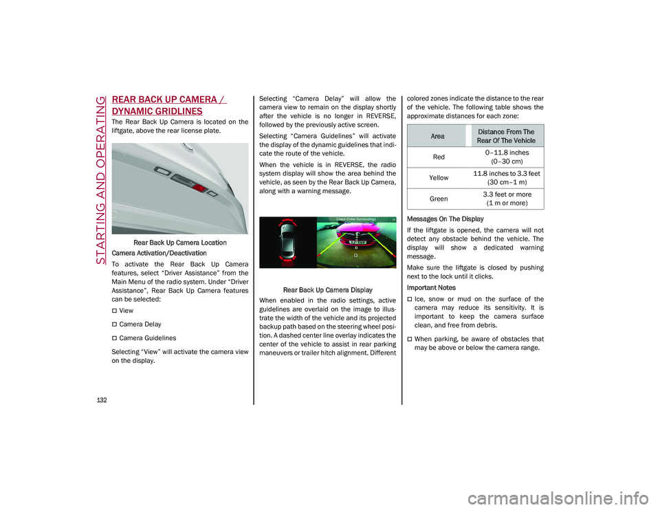
The Rear Back Up Camera is located on the
liftgate, above the rear license plate.Rear Back Up Camera Location
Camera Activation/Deactivation
To activate the Rear Back Up Camera
features, select “Driver Assistance” from the
Main Menu of the radio system. Under “Driver
Assistance”, Rear Back Up Camera features
can be selected:
View
Camera Delay
Camera Guidelines
Selecting “View” will activate the camera view
on the display. Selecting “Camera Delay” will allow the
camera view to remain on the display shortly
after the vehicle is no longer in REVERSE,
followed by the previously active screen.
Selecting “Camera Guidelines” will activate
the display of the dynamic guidelines that indi
-
cate the route of the vehicle.
When the vehicle is in REVERSE, the radio
system display will show the area behind the
vehicle, as seen by the Rear Back Up Camera,
along with a warning message.
Rear Back Up Camera Display
When enabled in the radio settings, active
guidelines are overlaid on the image to illus -
trate the width of the vehicle and its projected
backup path based on the steering wheel posi -
tion. A dashed center line overlay indicates the
center of the vehicle to assist in rear parking
maneuvers or trailer hitch alignment. Different colored zones indicate the distance to the rear
of the vehicle. The following table shows the
approximate distances for each zone:
Messages On The Display
If the liftgate is opened, the camera will not
detect any obstacle behind the vehicle. The
display will show a dedicated warning
message.
Make sure the liftgate is closed by pushing
next to the lock until it clicks.
Important Notes
Ice, snow or mud on the surface of the
camera may reduce its sensitivity. It is
important to keep the camera surface
clean, and free from debris.
When parking, be aware of obstacles that
may be above or below the camera range.
AreaDistance From The
Rear Of The Vehicle
Red 0–11.8 inches
(0–30 cm)
Yellow 11.8 inches to 3.3 feet
(30 cm–1 m)
Green 3.3 feet or more
(1 m or more)
21_GU_OM_EN_USC_t.book Page 132
Page 154 of 280

SAFETY
152
Operating Mode
The system may be activated/deactivated via
the radio system. To access the function,
select the following items on the main menu in
sequence:
1. “Driving Assistance”
2. “Blind Spot Alert”
“Blind Spot Alert”, “Visual” Mode
When the system is enabled, the warning light
within the door mirror on the side of the
detected object illuminates.
The visual warning on the mirror will blink if the
driver activates the turn signals, indicating a
lane change.
The warning light will be constant if the driver
stays in the same lane.
“Blind Spot Alert” Function Deactivation
When the system is deactivated (“Blind Spot
Alert” mode off), the BSM or RCP systems will
not emit an audible or a visual warning.
The BSM system will store the operating mode
that was active when the engine was stopped.
Each time the engine is started, the operating
mode stored previously will be recalled and
used
Ú
page 268.
Active Blind Spot Assist (ABSA) System — If
Equipped
The ABSA system is to help avoid/limit lateral
collisions with cars coming from adjacent lanes changing the vehicle’s trajectory in order
to try to keep it in the detected lane.
The system warns the driver about the pres
-
ence of other vehicles in the detection area by
illuminating the warning light located within
the door mirror on the side in which the other
vehicle was detected and by means of an
acoustic signal and/or vibration on the
steering wheel and/or counter-steering torque
on the steering wheel (if the respective item on
the “Driver Assistance” menu is set up and
then “Safety” is selected on the radio system).
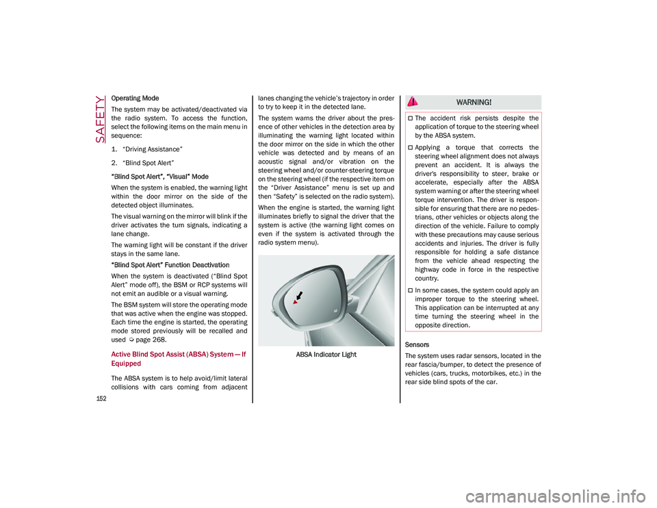
When the engine is started, the warning light
illuminates briefly to signal the driver that the
system is active (the warning light comes on
even if the system is activated through the
radio system menu).
ABSA Indicator Light Sensors
The system uses radar sensors, located in the
rear fascia/bumper, to detect the presence of
vehicles (cars, trucks, motorbikes, etc.) in the
rear side blind spots of the car.
WARNING!
The accident risk persists despite the
application of torque to the steering wheel
by the ABSA system.
Applying a torque that corrects the
steering wheel alignment does not always
prevent an accident. It is always the
driver's responsibility to steer, brake or
accelerate, especially after the ABSA
system warning or after the steering wheel
torque intervention. The driver is respon
-
sible for ensuring that there are no pedes -
trians, other vehicles or objects along the
direction of the vehicle. Failure to comply
with these precautions may cause serious
accidents and injuries. The driver is fully
responsible for holding a safe distance
from the vehicle ahead respecting the
highway code in force in the respective
country.
In some cases, the system could apply an
improper torque to the steering wheel.
This application can be interrupted at any
time turning the steering wheel in the
opposite direction.
21_GU_OM_EN_USC_t.book Page 152