2021 ALFA ROMEO STELVIO check engine
[x] Cancel search: check enginePage 4 of 280
2
READ THIS CAREFULLY
Refueling
Gas engines: Do not use fuel containing methanol or ethanol E85. Using these mixtures may cause misfiring and driving issues, as well
as damage vital components of the supply system.
Diesel engines: Do not use other products or mixtures as they may cause damage to the engine beyond repair and consequently invali -
date the warranty. For further details on the use of the correct fuel, see
Ú
page 255.
Starting The Engine
Make sure that the electric park brake is engaged and that the transmission is in PARK (P) or NEUTRAL (N). Next, press the brake pedal,
and then push the engine START/STOP button.
Parking On Flammable Material
The catalytic converter develops high temperatures during operation. Do not park the vehicle on potential fire hazards such as: grass, dry
leaves, pine needles or other flammable material.
Respecting The Environment
The vehicle is fitted with a system that carries out a continuous diagnosis of the emission-related components in order to help protect the
environment (if equipped).
Electrical Accessories
If you decide to add electrical accessories after purchasing the vehicle, with the risk of gradually draining the battery, contact an autho -
rized dealer. They can calculate the overall electrical requirement and check that the vehicle's electric system can support the required
load.
Scheduled Servicing
Correctly performed maintenance procedures are essential for ensuring that your vehicle continuously maintains its quality in perfor -
mance and safety features, environmental friendliness, and low running costs.
21_GU_OM_EN_USC_t.book Page 2
Page 14 of 280

12
JUMP STARTING .................................... 201
Remote Battery Connection Posts......202
Jump Starting Procedure.....................203
Bump Starting ..................................204
ENGINE OVERHEATING ......................... 204 MANUAL PARK RELEASE ...................... 205TOWING A DISABLED VEHICLE ............. 205
Four-Wheel Drive (AWD) Models .........206
TOW EYES .............................................. 206
ENHANCED ACCIDENT RESPONSE
SYSTEM (EARS) ..................................... 207EVENT DATA RECORDER (EDR) ............ 207
SERVICING AND MAINTENANCE
SCHEDULED SERVICING ....................... 208
Periodic Checks ...................................208
Heavy Usage Of The Vehicle ...............208
Maintenance Plan (2.0L Engine) ........209
Maintenance Plan (2.9L Engine) ........212
ENGINE COMPARTMENT....................... 214
Checking Levels — 2.0L Engine .......... 214
Checking Levels — 2.9L Engine .......... 215
Engine Oil ............................................. 215
Engine Coolant Fluid............................216
Washer Fluid For Windshield/
Headlights ............................................ 217 Brake Fluid ...........................................217
Automatic Transmission Activation
System Oil ............................................ 217 Useful Advice For Extending The Life Of
Your Battery..........................................217 Battery ..................................................217
Pressure Washing ................................ 218
BATTERY RECHARGING ......................... 218
Important Notes .................................. 218
VEHICLE MAINTENANCE ........................ 219
Engine Oil ............................................. 219
Engine Oil Filter ................................... 220
Engine Air Cleaner Filter ..................... 220
Air Conditioning System
Maintenance........................................ 220 Lubricating Moving Parts Of The
Bodywork ............................................. 220 Windshield Wiper................................. 221
Exhaust System ................................... 222
Cooling System .................................... 223
Braking System.................................... 224
Automatic Transmission ..................... 225
Replacing The Battery ......................... 225
Fuses .................................................... 225
Bulb Replacement ............................... 229
TIRES ...................................................... 233
Tire Safety Information .................... 233
Tires — General Information .............. 239
Spare Tires — If Equipped .................. 244
Wheel And Wheel Trim Care ............ 245
Tire Types ............................................. 246
Tire Chains and Traction Devices ....... 247
Tire Rotation Recommendations........ 247
DEPARTMENT OF TRANSPORTATION
UNIFORM TIRE QUALITY GRADES ......... 248
Treadwear ............................................ 248
Traction Grades ................................... 248
Temperature Grades ........................... 248
STORING THE VEHICLE ......................... 249 BODYWORK ........................................... 249
Protection Against Atmospheric
Agents .................................................. 249 Corrosion Warranty ............................. 250
Preserving The Bodywork .................. 250
INTERIORS ............................................. 251
Seats And Fabric Parts ....................... 251
Leather Seats ...................................... 251
Plastic And Coated Parts .................... 251
Alcantara Parts — If Equipped ............ 251
Genuine Leather Parts........................ 251
Carbon Fiber Parts .............................. 252
TECHNICAL SPECIFICATIONS
VEHICLE IDENTIFICATION
NUMBER (VIN) ....................................... 253
Vehicle Identification Number............ 253
Vehicle Identification Number
(VIN) Plate ............................................ 253
ENGINE .................................................. 254
POWER SUPPLY ..................................... 255 TRANSMISSION ..................................... 255BRAKES.................................................. 255
SUSPENSION ......................................... 256
STEERING .............................................. 256
DIMENSIONS ......................................... 257
Luggage Compartment Volume ......... 259
WEIGHTS ................................................ 259
21_GU_OM_EN_USC_t.book Page 12
Page 16 of 280
14
SYMBOL GLOSSARY
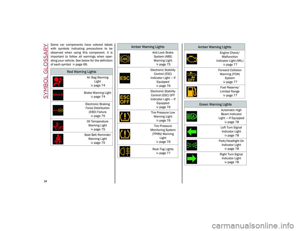
Some car components have colored labels
with symbols indicating precautions to be
observed when using this component. It is
important to follow all warnings when oper-
ating your vehicle. See below for the definition
of each symbol
Ú
page 69.
Red Warning Lights
Air Bag Warning
Light
Ú
page 74
Brake Warning Light
Ú
page 74
Electronic Braking Force Distribution (EBD) Failure
Ú
page 75
Oil Temperature Warning Light
Ú
page 75
Seat Belt Reminder Warning Light
Ú
page 75
Amber Warning Lights
Anti-Lock Brake
System (ABS)
Warning Light
Ú
page 75
Electronic Stability Control (ESC)
Indicator Light — If Equipped
Ú
page 76
Electronic Stability Control (ESC) OFF
Indicator Light — If Equipped
Ú
page 76
Tire Pressure Low Warning Light
Ú
page 76
Tire Pressure
Monitoring System (TPMS) Warning Light
Ú
page 76
Rear Fog Lights
Ú
page 77Engine Check/
Malfunction
Indicator Light (MIL)
Ú
page 77
Forward Collision Warning (FCW) System
Ú
page 77
Fuel Reserve/
Limited Range
Ú
page 77
Green Warning Lights
Automatic High
Beam Indicator
Light — If Equipped
Ú
page 78
Left Turn Signal Indicator Light
Ú
page 78
Park/Headlight On Indicator Light
Ú
page 78
Right Turn Signal Indicator Light
Ú
page 78
Amber Warning Lights
21_GU_OM_EN_USC_t.book Page 14
Page 22 of 280

GETTING TO KNOW YOUR VEHICLE
20
Programming And Requesting Additional
Key Fobs
Programming the key fob may be performed by
an authorized dealer.
NOTE:
Once a key fob is programmed to a vehicle,
it cannot be re-purposed and repro-
grammed to another vehicle.
Only key fobs that are programmed to the
vehicle electronics can be used to start and
operate the vehicle. Once a key fob is
programmed to a vehicle, it cannot be
programmed to any other vehicle.
Duplication of key fobs may be performed at
an authorized dealer. This procedure consists
of programming a blank key fob to the vehicle
electronics. A blank key fob is one that has
never been programmed
Ú
page 268.
NOTE:
When having the Engine Immobilizer
system serviced, bring all vehicle keys with
you to an authorized dealer.
For Quadrifoglio models, if you need a
replacement key fob, contact an authorized
dealer.
ENGINE IMMOBILIZER SYSTEM
The Engine Immobilizer system prevents unau-
thorized use of the vehicle by disabling engine
starting. The system does not need to be
enabled or activated. Operation is automatic,
regardless of whether the vehicle is locked or
unlocked.
The system uses a key fob, keyless push
button ignition and a Radio Frequency (RF)
receiver to prevent unauthorized vehicle oper
-
ation. Therefore, only key fobs that are
programmed to the vehicle can be used to
start and operate the vehicle. The system will
shut the engine off in two seconds if an invalid
key fob is used to start the engine.
After placing the ignition switch in the ON/RUN
position, the vehicle security light will turn on
for three seconds for a bulb check. If the light
remains on after the bulb check, it indicates
that there is a problem with the electronics. In
addition, if the light begins to flash after the
bulb check, it indicates that someone used an
invalid key fob to start the engine. Either of
these conditions will result in the engine being
shut off after two seconds. If the vehicle security light turns on during
normal vehicle operation (vehicle running for
longer than 10 seconds), it indicates that
there is a fault in the electronics. Should this
occur, have the vehicle serviced as soon as
possible by an authorized dealer.
All of the key fobs provided with your new
vehicle have been programmed to the vehicle
electronics.
NOTE:
A key fob that has not been programmed is
also considered an invalid key
Ú
page 268.
IGNITION SWITCH
Keyless Push Button Ignition
This feature allows the driver to operate the
ignition switch with the push of a button as
long as the key fob is in the passenger
compartment.
The START/STOP ignition button has several
operating modes. These modes are OFF, ACC,
and ON/RUN.
WARNING!
Always remove the key fobs from the
vehicle and lock all doors when leaving
the vehicle unattended.
Always remember to place the ignition in
the OFF mode.
CAUTION!
The Engine Immobilizer system is not
compatible with some aftermarket remote
starting systems. Use of these systems may
result in vehicle starting problems and loss
of security protection.
21_GU_OM_EN_USC_t.book Page 20
Page 64 of 280
GETTING TO KNOW YOUR VEHICLE
62
Closing The Hood
To close, lower the hood to approximately
16 inches (40 cm) from the engine compart-
ment then let it drop. Make sure that the hood
is completely closed and fully latched.
NOTE:
Since the hood is equipped with a double
locking system, one for each side, you must
check that it is closed on each side.
POWER LIFTGATE
Unlocking of the liftgate is electrically oper -
ated and is deactivated when the vehicle is in
motion.
If anything obstructs the power liftgate while it
is closing or opening, the liftgate will automat -
ically reverse to the closed or open position,
provided it meets sufficient resistance.
Opening
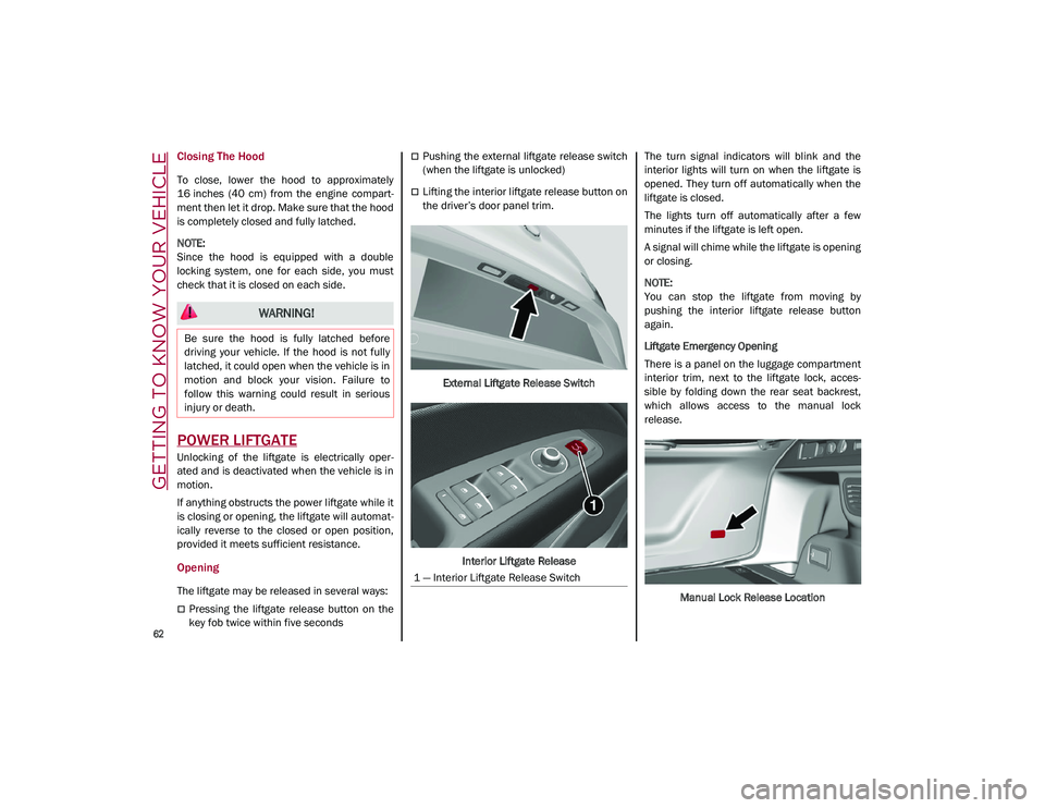
The liftgate may be released in several ways:
Pressing the liftgate release button on the
key fob twice within five seconds
Pushing the external liftgate release switch
(when the liftgate is unlocked)
Lifting the interior liftgate release button on
the driver’s door panel trim.
External Liftgate Release Switch
Interior Liftgate Release The turn signal indicators will blink and the
interior lights will turn on when the liftgate is
opened. They turn off automatically when the
liftgate is closed.
The lights turn off automatically after a few
minutes if the liftgate is left open.
A signal will chime while the liftgate is opening
or closing.
NOTE:
You can stop the liftgate from moving by
pushing the interior liftgate release button
again.
Liftgate Emergency Opening
There is a panel on the luggage compartment
interior trim, next to the liftgate lock, acces
-
sible by folding down the rear seat backrest,
which allows access to the manual lock
release.
Manual Lock Release Location
WARNING!
Be sure the hood is fully latched before
driving your vehicle. If the hood is not fully
latched, it could open when the vehicle is in
motion and block your vision. Failure to
follow this warning could result in serious
injury or death.
1 — Interior Liftgate Release Switch
21_GU_OM_EN_USC_t.book Page 62
Page 71 of 280
69
3. Instrument Cluster Display•The instrument cluster display features
a driver interactive display
Ú
page 69.
4. Fuel Gauge •The digital bar gauge shows the amount
of fuel in the tank.
• The fuel reserve/limited range
warning light turns on, a message is
displayed and there is an acoustic
signal when about 2.4 gallons (9 liters)
of fuel are left in the tank.
• The fuel pump symbol points to the
side of the vehicle where the fuel door is
located.
• P
roceeding further, the second white
notch will go off and the last one will become red, together with the indica-
tion "E" present at the bottom of the
tank. Fuel
Level Gauge
NOTE:
If the low fuel warning light switches on, refuel
at the earliest opportunity.
5. Speedometer •Indicates vehicle speed.
NOTE:
The hard telltales will illuminate for a bulb
check when the ignition is first cycled.
INSTRUMENT CLUSTER
DISPLAY
Instrument Cluster Display Description
This vehicle is equipped with a driver interac -
tive display that is located in the instrument
cluster.
When one or more of the doors have been
opened or closed and the ignition is in the OFF
position, the instrument cluster will display the
vehicle mileage for a few seconds.
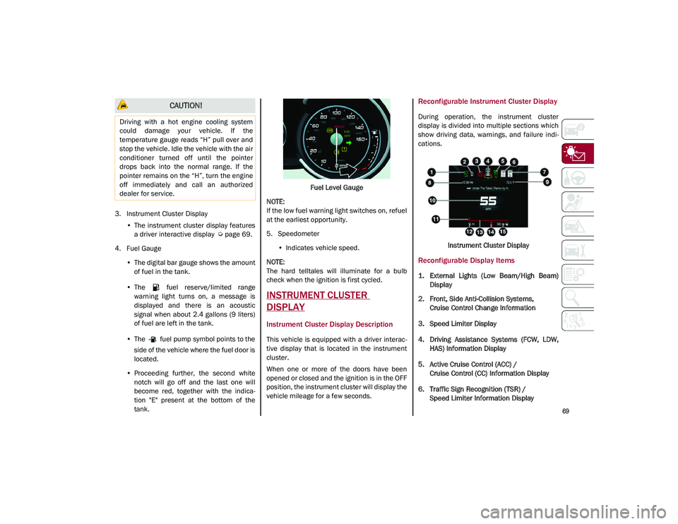
Reconfigurable Instrument Cluster Display
During operation, the instrument cluster
display is divided into multiple sections which
show driving data, warnings, and failure indi -
cations.
Instrument Cluster Display
Reconfigurable Display Items
1. External Lights (Low Beam/High Beam)Display
2. Front, Side Anti-Collision Systems, Cruise Control Change Information
3. Speed Limiter Display
4. Driving Assistance Systems (FCW, LDW, HAS) Information Display
5. Active Cruise Control (ACC) / Cruise Control (CC) Information Display
6. Traffic Sign Recognition (TSR) / Speed Limiter Information Display
CAUTION!
Driving with a hot engine cooling system
could damage your vehicle. If the
temperature gauge reads “H” pull over and
stop the vehicle. Idle the vehicle with the air
conditioner turned off until the pointer
drops back into the normal range. If the
pointer remains on the “H”, turn the engine
off immediately and call an authorized
dealer for service.
21_GU_OM_EN_USC_t.book Page 69
Page 77 of 280
75
Vehicles equipped with the Anti-Lock Brake
System (ABS) are also equipped with Elec-
tronic Brake Force Distribution (EBD). In the
event of an EBD failure, the Brake Warning
Light will turn on along with the ABS Light.
Immediate repair to the ABS system is
required.
Operation of the Brake Warning Light can be
checked by turning the ignition switch from the
OFF position to the ON/RUN position. The light
should illuminate for approximately two
seconds. The light should then turn off unless
the parking brake is applied or a brake fault is
detected. If the light does not illuminate, have
the light inspected by an authorized dealer.
The light also will turn on when the parking
brake is applied with the ignition switch in the
ON/RUN position.
NOTE:
This light shows only that the parking brake is
applied. It does not show the degree of brake
application.
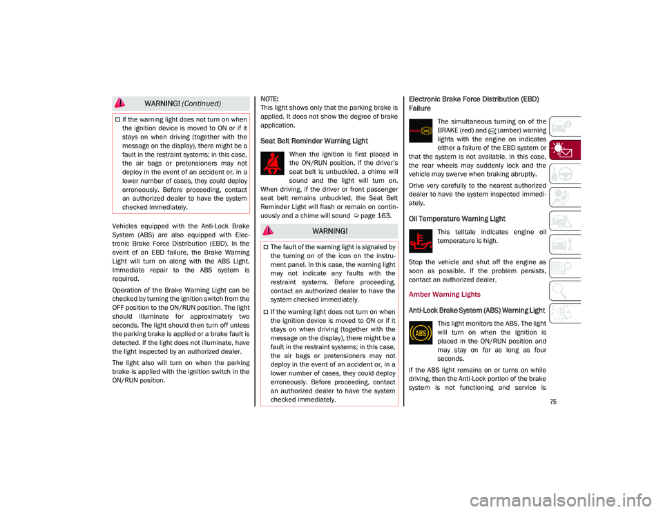
Seat Belt Reminder Warning Light
When the ignition is first placed in
the ON/RUN position, if the driver’s
seat belt is unbuckled, a chime will
sound and the light will turn on.
When driving, if the driver or front passenger
seat belt remains unbuckled, the Seat Belt
Reminder Light will flash or remain on contin -
uously and a chime will sound
Ú
page 163.
Electronic Brake Force Distribution (EBD)
Failure
The simultaneous turning on of the
BRAKE (red) and (amber) warning
lights with the engine on indicates
either a failure of the EBD system or
that the system is not available. In this case,
the rear wheels may suddenly lock and the
vehicle may swerve when braking abruptly.
Drive very carefully to the nearest authorized
dealer to have the system inspected immedi -
ately.
Oil Temperature Warning Light
This telltale indicates engine oil
temperature is high.
Stop the vehicle and shut off the engine as
soon as possible. If the problem persists,
contact an authorized dealer.
Amber Warning Lights
Anti-Lock Brake System (ABS) Warning Light
This light monitors the ABS. The light
will turn on when the ignition is
placed in the ON/RUN position and
may stay on for as long as four
seconds.
If the ABS light remains on or turns on while
driving, then the Anti-Lock portion of the brake
system is not functioning and service is
If the warning light does not turn on when
the ignition device is moved to ON or if it
stays on when driving (together with the
message on the display), there might be a
fault in the restraint systems; in this case,
the air bags or pretensioners may not
deploy in the event of an accident or, in a
lower number of cases, they could deploy
erroneously. Before proceeding, contact
an authorized dealer to have the system
checked immediately.
WARNING! (Continued)
WARNING!
The fault of the warning light is signaled by
the turning on of the icon on the instru -
ment panel. In this case, the warning light
may not indicate any faults with the
restraint systems. Before proceeding,
contact an authorized dealer to have the
system checked immediately.
If the warning light does not turn on when
the ignition device is moved to ON or if it
stays on when driving (together with the
message on the display), there might be a
fault in the restraint systems; in this case,
the air bags or pretensioners may not
deploy in the event of an accident or, in a
lower number of cases, they could deploy
erroneously. Before proceeding, contact
an authorized dealer to have the system
checked immediately.
21_GU_OM_EN_USC_t.book Page 75
Page 78 of 280
GETTING TO KNOW YOUR INSTRUMENT PANEL
76
required. However, the conventional brake
system will continue to operate normally if the
brake indicator light is not on.
If the ABS light is on, the brake system should
be serviced as soon as possible to restore the
benefits of Anti-Lock Brakes. If the ABS light
does not turn on when the ignition is placed in
the ON/RUN position, have the light inspected
by an authorized dealer.
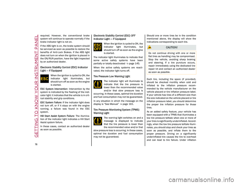
Electronic Stability Control (ESC) Indicator
Light — If Equipped
When the ignition is cycled to ON, the
indicator light illuminates, but
should turn off as soon as the engine
is started.
ESC System Intervention : Intervention by the
system is indicated by the flashing of the indi -
cator light: it indicates that the vehicle is in crit -
ical stability and grip conditions.
ESC System Failure : If the indicator light does
not turn off, or if it stays on with the engine
running, a failure was found in the ESC
system.
Hill Start Assist System Failure : The illumina-
tion of the indicator light indicates a Hill Start
Assist system failure.
In these cases, contact an authorized dealer
as soon as possible.
Electronic Stability Control (ESC) OFF
Indicator Light — If Equipped
When the ignition is cycled to ON, the
indicator light illuminates, but
should turn off as soon as the engine
is started.
The indicator light illuminates to indicate that
some active safety systems have been
partially or totally deactivated
Ú
page 145.
When the active safety systems are reacti -
vated, the indicator light turns off.
Tire Pressure Low Warning Light
The indicator light will illuminate to
indicate that the tire pressure is
lower than the recommended value
and/or that slow pressure loss is
occurring. In these cases, optimal tire duration
and fuel consumption may not be guaranteed.
In any situation in which the message on the
display is “See Manual”
Ú
page 161.
Tire Pressure Monitoring System (TPMS)
Warning Light
The warning light switches on and a
message is displayed to indicate
that the tire pressure is lower than
the recommended value and/or that
slow pressure loss is occurring. In these cases,
optimal tire duration and fuel consumption
may not be guaranteed. Should one or more tires be in the condition
mentioned above, the display will show the
indications corresponding to each tire.
Each tire, including the spare (if provided),
should be checked monthly when cold and
inflated to the inflation pressure recom
-
mended by the vehicle manufacturer on the
vehicle placard or tire inflation pressure label.
If your vehicle has tires of a different size than
the size indicated on the vehicle placard or tire
inflation pressure label, you should determine
the proper tire inflation pressure for those
tires.
As an added safety feature, your vehicle has
been equipped with a TPMS that illuminates a
low tire pressure telltale when one or more of
your tires is significantly underinflated. Accord -
ingly, when the low tire pressure telltale illumi -
nates, you should stop and check your tires as
soon as possible, and inflate them to the
proper pressure. Driving on a significantly
underinflated tire causes the tire to overheat
and can lead to tire failure. Under inflation
CAUTION!
Do not continue driving with one or more
flat tires as handling may be compromised.
Stop the vehicle, avoiding sharp braking
and steering. If a tire puncture occurs,
repair immediately using the dedicated tire
repair kit and contact an authorized dealer
as soon as possible.
21_GU_OM_EN_USC_t.book Page 76