2021 ALFA ROMEO STELVIO check engine
[x] Cancel search: check enginePage 127 of 280
125
Pushing the button a second time will turn the
system back on, and the indicator light will
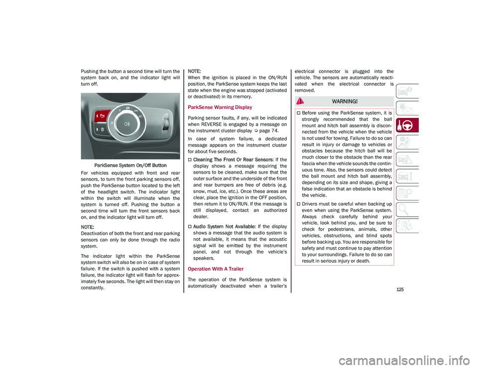
turn off.ParkSense System On/Off Button
For vehicles equipped with front and rear
sensors, to turn the front parking sensors off,
push the ParkSense button located to the left
of the headlight switch. The indicator light
within the switch will illuminate when the
system is turned off. Pushing the button a
second time will turn the front sensors back
on, and the indicator light will turn off.
NOTE:
Deactivation of both the front and rear parking
sensors can only be done through the radio
system.
The indicator light within the ParkSense
system switch will also be on in case of system
failure. If the switch is pushed with a system
failure, the indicator light will flash for approx -
imately five seconds. The light will then stay on
constantly.
NOTE:
When the ignition is placed in the ON/RUN
position, the ParkSense system keeps the last
state when the engine was stopped (activated
or deactivated) in its memory.
ParkSense Warning Display
Parking sensor faults, if any, will be indicated
when REVERSE is engaged by a message on
the instrument cluster display
Ú
page 74.
In case of system failure, a dedicated
message appears on the instrument cluster
for about five seconds.
Cleaning The Front Or Rear Sensors : If the
display shows a message requiring the
sensors to be cleaned, make sure that the
outer surface and the underside of the front
and rear bumpers are free of debris (e.g.
snow, mud, ice, etc.). Once these areas are
clear, place the ignition in the OFF position,
then return it to ON/RUN. If the message is
still displayed, contact an authorized
dealer.
Audio System Not Available : If the display
shows a message that the audio system is
not available, it means that the acoustic
signal will be emitted by the instrument
panel, and not through the vehicle’s
speakers.
Operation With A Trailer
The operation of the ParkSense system is
automatically deactivated when a trailer’s electrical connector is plugged into the
vehicle. The sensors are automatically reacti
-
vated when the electrical connector is
removed.
WARNING!
Before using the ParkSense system, it is
strongly recommended that the ball
mount and hitch ball assembly is discon -
nected from the vehicle when the vehicle
is not used for towing. Failure to do so can
result in injury or damage to vehicles or
obstacles because the hitch ball will be
much closer to the obstacle than the rear
fascia when the vehicle sounds the contin -
uous tone. Also, the sensors could detect
the ball mount and hitch ball assembly,
depending on its size and shape, giving a
false indication that an obstacle is behind
the vehicle.
Drivers must be careful when backing up
even when using the ParkSense system.
Always check carefully behind your
vehicle, look behind you, and be sure to
check for pedestrians, animals, other
vehicles, obstructions, and blind spots
before backing up. You are responsible for
safety and must continue to pay attention
to your surroundings. Failure to do so can
result in serious injury or death.
21_GU_OM_EN_USC_t.book Page 125
Page 135 of 280
133
REFUELING THE VEHICLE
Refueling The Vehicle
Before refueling, make sure that the fuel type
is correct.
Also, stop the engine before refueling.
NOTE:
An inefficient catalytic converter leads to
harmful exhaust emissions, thus contributing
to air pollution.
Refueling Capacity
To ensure that you fill the tank completely, top
off twice after the first click of the fuel nozzle.
Further top-off could cause faults in the fuel
feeding system.
Refueling Procedure
The fuel filler door is unlocked when the
central door locking system is unlocked. It is
automatically locked when the central locking
system is applied.
Opening The Fuel Filler Door
To refuel proceed as follows:
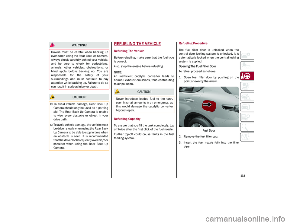
1. Open fuel filler door by pushing on thepoint shown by the arrow.
Fuel Door
2. Remove the fuel filler cap.
3. Insert the fuel nozzle fully into the filler pipe.
WARNING!
Drivers must be careful when backing up
even when using the Rear Back Up Camera.
Always check carefully behind your vehicle,
and be sure to check for pedestrians,
animals, other vehicles, obstructions, or
blind spots before backing up. You are
responsible for the safety of your
surroundings and must continue to pay
attention while backing up. Failure to do so
can result in serious injury or death.
CAUTION!
To avoid vehicle damage, Rear Back Up
Camera should only be used as a parking
aid. The Rear Back Up Camera is unable
to view every obstacle or object in your
drive path.
To avoid vehicle damage, the vehicle must
be driven slowly when using the Rear Back
Up Camera to be able to stop in time when
an obstacle is seen. It is recommended
that the driver look frequently over his/her
shoulder when using the Rear Back Up
Camera.
CAUTION!
Never introduce leaded fuel to the tank,
even in small amounts in an emergency, as
this would damage the catalytic converter
beyond repair.
21_GU_OM_EN_USC_t.book Page 133
Page 141 of 280
139
(Continued)
Consider the following items when computing
the weight on the rear axle of the vehicle:
The tongue weight of the trailer.
The weight of any other type of cargo or
equipment put in or on your vehicle.
The weight of the driver and all passengers.
NOTE:
Remember that everything put into or on the
trailer adds to the load on your vehicle. Also,
additional factory-installed options or
dealer-installed options must be considered
as part of the total load on your vehicle. Refer
to the “Tire And Loading Information” placard
for the maximum combined weight of occu -
pants and cargo for your vehicle.
Towing Requirements
To promote proper break-in of your new
vehicle drivetrain components, the following
guidelines are recommended:
Towing Requirements — Tires
Do not attempt to tow a trailer while using a
compact spare tire.
Do not drive more than 50 mph (80 km/h)
when towing while using a full size spare
tire.
Proper tire inflation pressures are essential
to the safe and satisfactory operation of
your vehicle.
Check the trailer tires for proper tire infla -
tion pressures before trailer usage.
Check for signs of tire wear or visible tire
damage before towing a trailer.
Replacing tires with a higher load carrying
capacity will not increase the vehicle's
GVWR and GAWR limits.
For proper tire inflation procedures
Ú
page 233.
WARNING!
Improper towing can lead to a collision.
Follow these guidelines to make your trailer
towing as safe as possible:
Make certain that the load is secured in
the trailer and that it will not shift during
travel. When trailering cargo that is not
fully secured, dynamic load shifts can
occur that may be difficult for the driver to
control. You could lose control of your
vehicle and have a collision.
When hauling cargo, or towing a trailer, do
not overload your vehicle or trailer. Over -
loading can cause a loss of control, poor
performance, or damage to brakes, axle,
engine, transmission, steering, suspen -
sion, chassis structure, or tires.
Safety chains must always be used
between your vehicle and trailer. Always
connect the chains to the frame or hook
retainers of the vehicle hitch. Cross the
chains under the trailer tongue and allow
enough slack for turning corners.
Vehicles with trailers should not be parked
on a grade. When parking, apply the
parking brake on the tow vehicle. Put the
tow vehicle transmission in PARK. Always
block or "chock" the trailer wheels.
GCWR must not be exceeded.
Total weight must be distributed between
the tow vehicle and the trailer such that
the following four ratings are not
exceeded:
• GVWR
• GTW
• GAWR
• Tongue weight rating for the trailer
hitch utilized.
WARNING! (Continued) CAUTION!
Do not tow a trailer at all during the first
500 miles (805 km) the new vehicle is
driven. The engine, axle or other parts
could be damaged.
Then, during the first 500 miles (805 km)
that a trailer is towed, do not drive over
50 mph (80 km/h) and do not make
starts at full throttle. This helps the engine
and other parts of the vehicle wear in at
the heavier loads.
21_GU_OM_EN_USC_t.book Page 139
Page 144 of 280
STARTING AND OPERATING
142
Removing The Receiver
When the receiver is no longer needed, discon-
nect the electrical connections and remove it
from its position using the directions below:
1. Remove the safety split ring from the locking pin.
2. Pull the locking pin out of the trailer hitch.
3. Remove the receiver from the trailer hitch.
SUGGESTIONS FOR DRIVING
Saving Fuel
Below are some suggestions which may help
you save fuel and lower the amount of harmful
emissions released into the atmosphere.
Vehicle Maintenance
Checks and operations should be carried out
in accordance with the Maintenance Plan
Ú
page 208.
Tires
Check the tire pressures at least once every
four weeks: if the pressure is too low,
consumption levels increase as resistance to
rolling is higher.
NOTE:
Tire pressure that is too high can cause
premature tire wear, reduced control, etc. Unnecessary Loads
Do not travel with an overloaded liftgate. The
weight of the vehicle and its arrangement
greatly affect fuel consumption and stability.
Electric Devices
Use electrical systems only for the amount of
time needed. The rear window defroster, addi
-
tional headlights, windshield wipers and
heater blower fan require a considerable
amount of energy; increasing the current
uptake increases fuel consumption (by up to
+25% when city driving).
Climate Control System
Using the climate control system will increase
consumption: use standard ventilation when
the temperature outside permits.
Devices For Aerodynamic Control
The use of non-certified devices for aerody -
namic control may adversely affect air drag
and consumption levels.
Driving Style
Starting
Do not warm up the engine at low or high revs
when the vehicle is stationary; this causes the
engine to warm up more slowly, thereby
increasing fuel consumption and emissions. It
is therefore advisable to drive off immediately,
slowly, avoiding high speeds: by doing this the
engine will warm up more quickly. Unnecessary Actions
Avoid revving up when starting at traffic lights
or before stopping the engine. This action is
unnecessary and causes increased fuel
consumption and pollution.
Gear Selection
Use a high gear when traffic and road condi
-
tions allow it. Using a low gear for faster accel -
eration will increase fuel consumption.
Improper use of a high gear increases
consumption, emissions and engine wear.
Max. Speed
Fuel consumption considerably increases as
speed increases. Maintain a constant speed,
avoiding unnecessary braking and accelera -
tion, which cost in terms of both fuel consump -
tion and emissions.
Acceleration
Accelerating violently severely affects
consumption and emissions: acceleration
should be gradual and should not exceed the
maximum torque.Conditions Of Use
Cold Starting
Short trips and frequent cold starts will not
allow the engine to reach optimum operating
temperature. This results in a significant
increase in consumption levels (from +15 to
+30% in city driving) and emissions.
21_GU_OM_EN_USC_t.book Page 142
Page 145 of 280
143
Traffic And Road Conditions
High fuel consumption is caused by heavy
traffic, for instance when traveling in traffic
with frequent use of low gears or in cities with
many traffic lights. Winding mountain roads
and rough road surfaces also adversely affect
consumption.
Stops In Traffic
During prolonged stops (e.g. railway cross-
ings), turn off the engine.
Performance — Quadrifoglio
This vehicle is equipped with an engine
capable of delivering exceptionally fast accel -
eration and speed:
Peak power: 505 HP at 6,500 RPM.
Peak torque: 443 ft-lbs at 2,500–5,000 RPM.
Top speed: 176 mph (283 km/h).
Acceleration from 0 to 60 mph (0 to 100 km/h):
3.6 seconds.
For safe driving, it is essential, particularly
during the first days of use, to get to know the
car by driving carefully and gradually discov -
ering its performance.
Brakes
The car braking system may be available with
four carbon-ceramic material brake discs, one
on each wheel. In order to guarantee the maximum braking
capacity for the first use, Alfa Romeo performs
a "run-in" procedure for discs and pads directly
at the factory.
The use of carbon-ceramic material brake
discs guarantees braking features (better
deceleration/pedal load ratio, braking
distances, fading resistance) proportional to
the dynamic features of the car in addition to
considerably decreasing the unsprung compo
-
nent weight.
The materials used and the structural features
of the system could generate unusual noises
which have absolutely no adverse effect on
correct operation and reliability of the braking
system.
Greater pressure may need to be applied to
the brake pedal the first time to keep the same
braking capacities in presence of condensa -
tion or salt on the braking surfaces, for
example after washing or if the car is not used
for a long time.
NOTE:
Given the high technological level of this
system, any servicing on it must be performed
by an authorized dealer which exclusively has
the skills needed for the repair and mainte -
nance operations. In case of intensive, high-performance use of
the car, have the efficiency of the
carbon-ceramic material braking system
inspected as shown on the Maintenance Plan
at an authorized dealer.
Driving On Race Tracks
Before driving on a track using a racing style, it
is necessary to:
Attend a race track driving course.
Check the liquid levels in the engine
compartment
Ú
page 208.
Have the car inspected at an authorized
dealer.
Remember that the car was not designed to be
driven exclusively on the race track and that
this use increases stress and component
wear.
NOTE:
Quadrifoglio front brakes are equipped with
Non-Asbestos Organic (NAO) type pads. These
pads are NOT suitable for high thermal loads
(for example track use). If you want to use
vehicle on a track it is recommended to use
the optional CCM Brakes (Carbon Ceramic
Brake disc).
21_GU_OM_EN_USC_t.book Page 143
Page 152 of 280
SAFETY
150
For the operation of the DAA, LDW, LKA, HAS,
TJA, ACC, ISC, or TSR systems, see
Ú
page 86.
NOTE:
When driving on two-way roads where there is
no lane dividing center line (e.g. on unpaved
roads), the use of the ABSA, HAS, TJA, and LKA
systems is strongly discouraged as the system
could detect the entire road as single-lane
dividing lines.
NOTE:
The driving assistance systems are designed
to aid in driving the car. The driver must always
maintain a sufficient level of attention to the
traffic and road conditions and control the
trajectory of the car.
Blind Spot Monitoring (BSM) System — If
Equipped
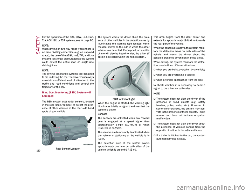
The BSM system uses radar sensors, located
in the rear fascia/bumper, to detect the pres -
ence of other vehicles in the rear side blind
spots of your vehicle.
Rear Sensor Location The system warns the driver about the pres
-
ence of other vehicles in the detection area by
illuminating the warning light located within
the door mirror on the side in which the other
vehicle was detected. If equipped, an audible
chime will also be heard to alert the driver (if
option is selected within the radio system).
BSM Indicator Light
When the engine is started, the warning light
illuminates briefly to signal the driver that the
system is active.
Sensors
The sensors are activated when any forward
gear is engaged at a speed higher than
approximately 6 mph (10 km/h) or when
REVERSE is engaged.
The sensors are temporarily deactivated when
the vehicle is stationary or the vehicle is in
PARK.
The detection area of the system covers
approximately one lane on both sides of the
vehicle, which is around 9 ft (3 m). This area begins from the door mirror and
extends for approximately 19 ft (6 m) towards
the rear part of the vehicle.
When the sensors are active, the system moni
-
tors the detection areas on both sides of the
vehicle and warns the driver about the
possible presence of vehicles in these areas.
While driving, the system monitors the detec -
tion zone in three different situations:
when you are being overtaken by a vehicle;
when you are overtaking a vehicle;
when a vehicle approaches from the side;
to check whether it is necessary to send a
signal to the driver on both sides.
NOTE:
The system does not alert the driver of the
presence of fixed objects (e.g. safety
barriers, poles, walls, etc.). However, in
some circumstances, the system may acti -
vate in the presence of these objects. This is
normal and does not indicate a system
malfunction.
The system does not alert the driver about
the presence of vehicles coming from the
opposite direction, in the adjacent lanes.
If a trailer is hitched to the car, the system
automatically deactivates.
21_GU_OM_EN_USC_t.book Page 150
Page 171 of 280
169
Supplemental Restraint Systems (SRS)
Some of the safety features described in this
section may be standard equipment on some
models, or may be optional equipment on
others. If you are not sure, ask an authorized
dealer.
The air bag system must be ready to protect
you in a collision. The Occupant Restraint
Controller (ORC) monitors the internal circuits
and interconnecting wiring associated with the
electrical Air Bag System Components. Your
vehicle may be equipped with the following Air
Bag System Components:
Air Bag System Components
Occupant Restraint Controller (ORC)
Air Bag Warning Light
Steering Wheel and Column
Instrument Panel
Knee Impact Bolsters
Driver and Front Passenger Air Bags
Seat Belt Buckle Switch
Supplemental Side Air Bags
Supplemental Knee Air Bags
Front and Side Impact Sensors
Seat Belt Pretensioners
Seat Track Position Sensors
Air Bag Warning Light
The Occupant Restraint Controller
(ORC) monitors the readiness of the
electronic parts of the air bag system
whenever the ignition switch is in the
START or ON/RUN position. If the ignition
switch is in the OFF position or in the ACC posi -
tion, the air bag system is not on and the air
bags will not inflate.
The ORC contains a backup power supply
system that may deploy the air bag system
even if the battery loses power or it becomes
disconnected prior to deployment.
The ORC turns on the Air Bag Warning Light in
the instrument panel for approximately four to
eight seconds for a self-check when the igni -
tion switch is first in the ON/RUN position.
After the self-check, the Air Bag Warning Light
will turn off. If the ORC detects a malfunction
in any part of the system, it turns on the Air
Bag Warning Light, either momentarily or continuously. A single chime will sound to alert
you if the light comes on again after initial
startup.
The ORC also includes diagnostics that will illu
-
minate the instrument panel Air Bag Warning
Light if a malfunction is detected that could
affect the air bag system. The diagnostics also
record the nature of the malfunction. While
the air bag system is designed to be mainte -
nance free, if any of the following occurs, have
an authorized dealer service the air bag
system immediately.The Air Bag Warning Light does not come on
during the four to eight seconds when the
ignition switch is first in the ON/RUN posi -
tion.
The Air Bag Warning Light remains on after
the four to eight-second interval.
The Air Bag Warning Light comes on inter-
mittently or remains on while driving.
NOTE:
If the speedometer, tachometer, or any engine
related gauges are not working, the Occupant
Restraint Controller (ORC) may also be
disabled. In this condition the air bags may not
be ready to inflate for your protection. Have an
authorized dealer service the air bag system
immediately.
Do not use the Automatic Locking Mode to
restrain occupants who are wearing the
seat belt or children who are using booster
seats. The locked mode is only used to
install rear-facing or forward-facing child
restraints that have a harness for
restraining the child.
WARNING! (Continued)
21_GU_OM_EN_USC_t.book Page 169
Page 178 of 280
SAFETY
176
NOTE:
After an accident, remember to cycle the igni-
tion to the OFF position and remove the key
from the ignition switch to avoid draining the
battery. Carefully check the vehicle for fuel
leaks in the engine compartment and on the
ground near the engine compartment and fuel
tank before resetting the system and starting
the engine. If there are no fuel leaks or
damage to the vehicle electrical devices (e.g.
headlights) after an accident, reset the system by following the procedure described below. If
you have any doubt, contact an authorized
dealer.
Enhanced Accident Response System
Reset Procedure
After the event occurs, when the system is
active, a message regarding fuel cutoff is
displayed. Turn the ignition switch from igni
-
tion ACC or ON/RUN to ignition OFF. Carefully
check the vehicle for fuel leaks in the engine compartment and on the ground near the
engine compartment and fuel tank before
resetting the system and starting the engine.
Depending on the nature of the event the left
and right turn signal lights, located in the
instrument panel, may both be blinking and
will continue to blink. In order to move your
vehicle to the side of the road, you must follow
the system reset procedure.
Customer Action
NOTE:
Each step MUST BE held for at least two secondsCustomer Will See
1. Turn ignition OFF. (Turn Signal Switch Must be placed in
Neutral State).
2. Turn ignition ACC. Right turn light BLINKS.
Left turn light is OFF.
3. Turn right turn signal switch ON. Right turn light is ON SOLID.
Left turn light BLINKS.
4. Place turn signal in neutral state. Right turn light is OFF.
Left turn light BLINKS.
5. Turn left turn signal switch ON. Right turn light BLINKS.
Left turn light is ON SOLID.
6. Place turn signal in neutral state. Right turn light BLINKS.
Left turn light is OFF.
7. Turn right turn signal switch ON. Right turn light is ON SOLID.
Left turn light BLINKS.
8. Place turn signal in neutral state. Right turn light is OFF.
Left turn light BLINKS.
21_GU_OM_EN_USC_t.book Page 176