2021 ALFA ROMEO STELVIO battery
[x] Cancel search: batteryPage 195 of 280
193
To Use SOS - Emergency Call
Push and hold the SOS - Emergency Call
button for a few seconds. The LED, located
next to the SOS button, will blink once and
then stay on indicating a call has been placed.
NOTE:
If the SOS - Emergency Call button is acciden-
tally pushed, there is a 10 second delay before
the call is placed. The system will issue a
verbal alert that a call is about to be made. To
cancel the call connection, push the SOS -
Emergency Call button again.
Once a connection between the vehicle and an
emergency service operator is made, the SOS
- Emergency Call system will transmit the
following important vehicle information to the
operator:
Indication that the occupant placed an SOS
- Emergency Call.
The Vehicle Identification Number (VIN).
The last known GPS coordinates of the
vehicle.
You will then be able to speak with the emer -
gency service operator to determine if addi -
tional help is needed.
The SOS - Emergency Call has priority over
other audio sources, which will be muted. If
you have a phone connected via Bluetooth, it
is disconnected and reconnected at the end of
the SOS - Emergency Call. Voice prompts will
guide you during the SOS - Emergency Call. If a connection is made between an emergency
service operator and your vehicle, emergency
service operators may record conversations
and sounds within your vehicle once a connec
-
tion is made, and by using the service you
consent to having this information shared.
NOTE:
If you have not subscribed to the SOS service
or if the service is not available or has expired,
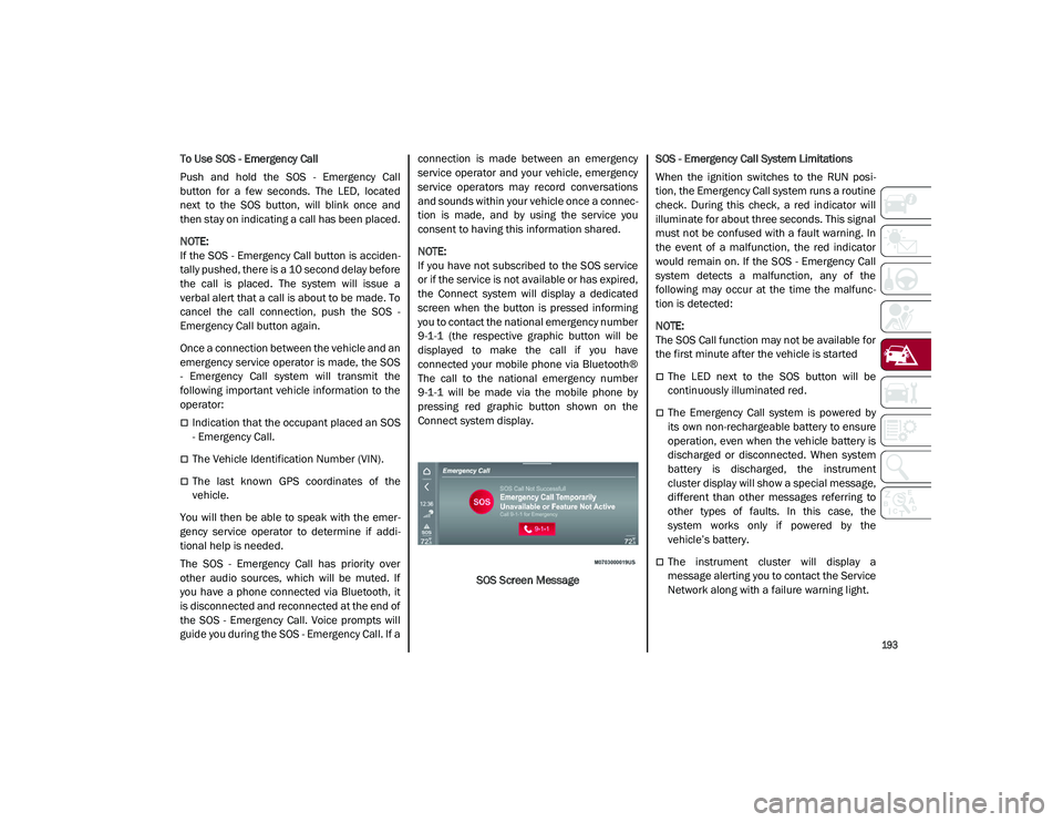
the Connect system will display a dedicated
screen when the button is pressed informing
you to contact the national emergency number
9-1-1 (the respective graphic button will be
displayed to make the call if you have
connected your mobile phone via Bluetooth®
The call to the national emergency number
9-1-1 will be made via the mobile phone by
pressing red graphic button shown on the
Connect system display.
SOS Screen Message SOS - Emergency Call System Limitations
When the ignition switches to the RUN posi
-
tion, the Emergency Call system runs a routine
check. During this check, a red indicator will
illuminate for about three seconds. This signal
must not be confused with a fault warning. In
the event of a malfunction, the red indicator
would remain on. If the SOS - Emergency Call
system detects a malfunction, any of the
following may occur at the time the malfunc -
tion is detected:
NOTE:
The SOS Call function may not be available for
the first minute after the vehicle is started
The LED next to the SOS button will be
continuously illuminated red.
The Emergency Call system is powered by
its own non-rechargeable battery to ensure
operation, even when the vehicle battery is
discharged or disconnected. When system
battery is discharged, the instrument
cluster display will show a special message,
different than other messages referring to
other types of faults. In this case, the
system works only if powered by the
vehicle’s battery.
The instrument cluster will display a
message alerting you to contact the Service
Network along with a failure warning light.
21_GU_OM_EN_USC_t.book Page 193
Page 196 of 280
IN CASE OF EMERGENCY
194
(Continued)
Even if the SOS - Emergency Call system is fully
functional, external or uncontrolled factors
may prevent or stop SOS - Emergency Call
operation. These include, but are not limited
to, the following factors:
The ignition is in OFF position.
The vehicle’s electrical systems are not
intact.
The SOS - Emergency Call system software
and/or hardware is damaged during a
vehicle collision.
There are network problems that could limit
or impair service operation (e.g., error by
operator, busy network, bad weather, etc.).
If the vehicle battery connection fails due to a
collision or accident, the system can support
an SOS - Emergency Call for a limited period of
time. If the battery is disconnected for service,
the system turns off. In this case, it will be
possible to make an SOS - Emergency Call only
when the battery is reconnected to the
vehicle’s electrical system.
System Requirements
Vehicle must have an operable 3G network
connection.
Vehicle must be powered with a properly
functioning electrical system.
The ignition must be in the RUN or ACC posi -
tion.
WARNING!
Never place anything on or near the
vehicle’s 3G and GPS aerials. You could
prevent 3G and GPS signal reception,
which can prevent your vehicle from
placing an emergency call. An operable
3G network connection and a GPS signal
is required for the SOS-Emergency Call
system to function properly.
Do not add any aftermarket electrical
equipment to the vehicle’s electrical
system. This may prevent your vehicle
from sending a signal to initiate an emer -
gency call. To avoid interference that can
cause the SOS-Emergency Call system to
fail, never add aftermarket equipment
(e.g., two-way mobile radio, CB radio, data
recorder, etc.) to your vehicle’s electrical
system or modify the antennas on your
vehicle. IF YOUR VEHICLE AND SYSTEM
LOSES BATTERY POWER FOR ANY
REASON (INCLUDING DURING OR AFTER
AN ACCIDENT) THE SOS FEATURES, APPS
AND SERVICES AMONG OTHERS WILL
NOT OPERATE.
The Occupant Restraint Controller (ORC)
turns on the air bag warning light in the
instrument cluster if a malfunction in any
part of the air bag system is detected. If
the air bag warning light is illuminated, the
air bag system may not be working prop -
erly and the SOS-Emergency Call system
may not be able to send a signal to an
emergency service operator. If the air bag
warning light is illuminated, contact the
Service Network to have the air bag
system checked immediately.
Ignoring the LED on the SOS-Emergency
Call button could mean you will not have
emergency call services if needed. If the
LED on SOS-Emergency Call button is illu -
minated red, contact the Service Network
to have the emergency call system
checked immediately.
If anyone in the vehicle could be in danger
(e.g., fire or smoke is visible, dangerous
road conditions or location), do not wait
for voice contact from an emergency
service operator. All occupants should exit
the vehicle immediately and move to a
safe location.
Failure to perform scheduled mainte -
nance and regularly inspect your vehicle
may result in vehicle damage, accident or
injury.
WARNING! (Continued)
21_GU_OM_EN_USC_t.book Page 194
Page 203 of 280
201
11. Apply the adhesive label from the sealantbottle where it can be easily seen by the
driver as a reminder that the tire has been
treated with a Tire Service Kit, as well as
not to exceed the speed restriction for the
treated tire.
NOTE:
Only use original sealant cartridges, which can
be purchased at an authorized dealer.
Checking And Restoring Tire Pressure
The compressor can also be used to check
and, if necessary, restore the tire pressure.
Proceed as follows:
1. Make sure that the power switch is in the
O (off) position.
2. Connect the hose directly to the valve on the tire to be inflated.
3. Insert the plug into the socket in the passenger compartment or in the cargo
area and start the engine.
4. Start the compressor by putting the power switch to I (on). As soon as the correct
pressure is reached, put the power switch
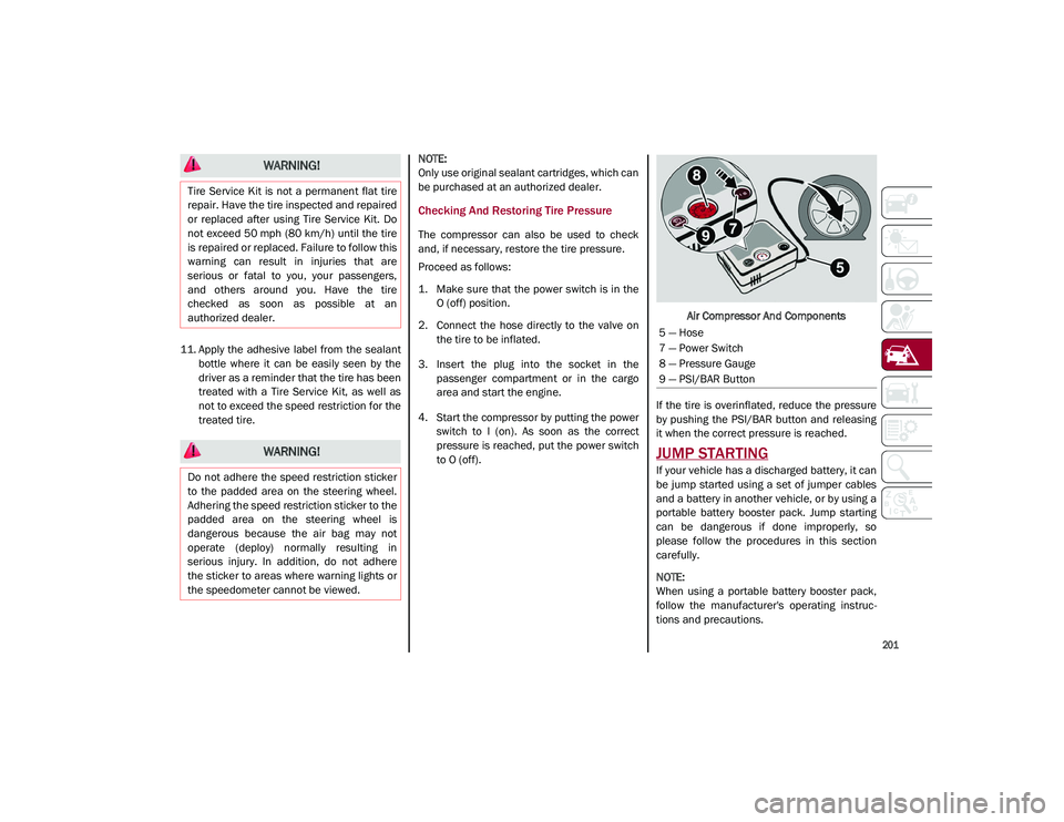
to O (off). Air Compressor And Components
If the tire is overinflated, reduce the pressure
by pushing the PSI/BAR button and releasing
it when the correct pressure is reached.
JUMP STARTING
If your vehicle has a discharged battery, it can
be jump started using a set of jumper cables
and a battery in another vehicle, or by using a
portable battery booster pack. Jump starting
can be dangerous if done improperly, so
please follow the procedures in this section
carefully.
NOTE:
When using a portable battery booster pack,
follow the manufacturer's operating instruc -
tions and precautions.
WARNING!
Tire Service Kit is not a permanent flat tire
repair. Have the tire inspected and repaired
or replaced after using Tire Service Kit. Do
not exceed 50 mph (80 km/h) until the tire
is repaired or replaced. Failure to follow this
warning can result in injuries that are
serious or fatal to you, your passengers,
and others around you. Have the tire
checked as soon as possible at an
authorized dealer.
WARNING!
Do not adhere the speed restriction sticker
to the padded area on the steering wheel.
Adhering the speed restriction sticker to the
padded area on the steering wheel is
dangerous because the air bag may not
operate (deploy) normally resulting in
serious injury. In addition, do not adhere
the sticker to areas where warning lights or
the speedometer cannot be viewed.
5 — Hose
7 — Power Switch
8 — Pressure Gauge
9 — PSI/BAR Button
21_GU_OM_EN_USC_t.book Page 201
Page 204 of 280
IN CASE OF EMERGENCY
202
Remote Battery Connection Posts
The remote posts of the battery for jump
starting can be found inside the engine
compartment. The battery itself is located in
the luggage compartment.
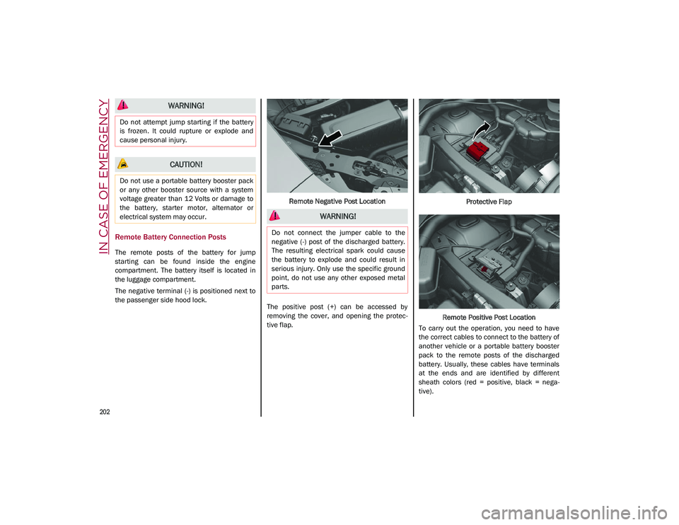
The negative terminal (-) is positioned next to
the passenger side hood lock.Remote Negative Post Location
The positive post (+) can be accessed by
removing the cover, and opening the protec -
tive flap. Protective Flap
Remote Positive Post Location
To carry out the operation, you need to have
the correct cables to connect to the battery of
another vehicle or a portable battery booster
pack to the remote posts of the discharged
battery. Usually, these cables have terminals
at the ends and are identified by different
sheath colors (red = positive, black = nega -
tive).
WARNING!
Do not attempt jump starting if the battery
is frozen. It could rupture or explode and
cause personal injury.
CAUTION!
Do not use a portable battery booster pack
or any other booster source with a system
voltage greater than 12 Volts or damage to
the battery, starter motor, alternator or
electrical system may occur.
WARNING!
Do not connect the jumper cable to the
negative (-) post of the discharged battery.
The resulting electrical spark could cause
the battery to explode and could result in
serious injury. Only use the specific ground
point, do not use any other exposed metal
parts.
21_GU_OM_EN_USC_t.book Page 202
Page 205 of 280
203
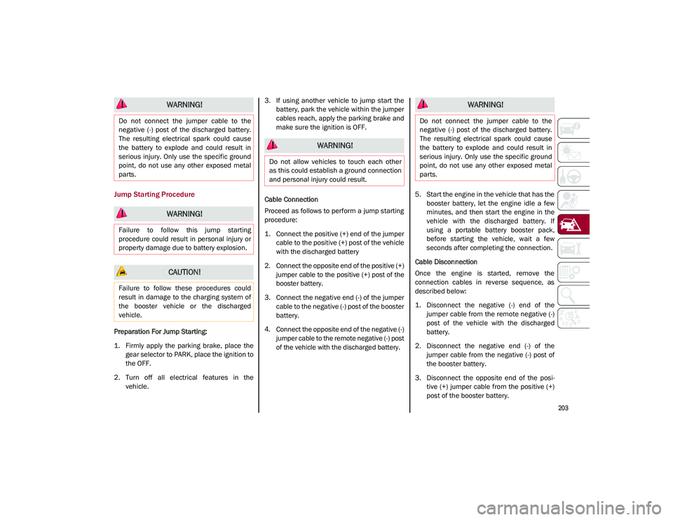
Jump Starting Procedure
Preparation For Jump Starting:
1. Firmly apply the parking brake, place thegear selector to PARK, place the ignition to
the OFF.
2. Turn off all electrical features in the vehicle. 3. If using another vehicle to jump start the
battery, park the vehicle within the jumper
cables reach, apply the parking brake and
make sure the ignition is OFF.
Cable Connection
Proceed as follows to perform a jump starting
procedure:
1. Connect the positive (+) end of the jumper cable to the positive (+) post of the vehicle
with the discharged battery
2. Connect the opposite end of the positive (+) jumper cable to the positive (+) post of the
booster battery.
3. Connect the negative end (-) of the jumper cable to the negative (-) post of the booster
battery.
4. Connect the opposite end of the negative (-) jumper cable to the remote negative (-) post
of the vehicle with the discharged battery. 5. Start the engine in the vehicle that has the
booster battery, let the engine idle a few
minutes, and then start the engine in the
vehicle with the discharged battery. If
using a portable battery booster pack,
before starting the vehicle, wait a few
seconds after completing the connection.
Cable Disconnection
Once the engine is started, remove the
connection cables in reverse sequence, as
described below:
1. Disconnect the negative (-) end of the jumper cable from the remote negative (-)
post of the vehicle with the discharged
battery.
2. Disconnect the negative end (-) of the jumper cable from the negative (-) post of
the booster battery.
3. Disconnect the opposite end of the posi -
tive (+) jumper cable from the positive (+)
post of the booster battery.
WARNING!
Do not connect the jumper cable to the
negative (-) post of the discharged battery.
The resulting electrical spark could cause
the battery to explode and could result in
serious injury. Only use the specific ground
point, do not use any other exposed metal
parts.
WARNING!
Failure to follow this jump starting
procedure could result in personal injury or
property damage due to battery explosion.
CAUTION!
Failure to follow these procedures could
result in damage to the charging system of
the booster vehicle or the discharged
vehicle.
WARNING!
Do not allow vehicles to touch each other
as this could establish a ground connection
and personal injury could result.
WARNING!
Do not connect the jumper cable to the
negative (-) post of the discharged battery.
The resulting electrical spark could cause
the battery to explode and could result in
serious injury. Only use the specific ground
point, do not use any other exposed metal
parts.
21_GU_OM_EN_USC_t.book Page 203
Page 206 of 280
IN CASE OF EMERGENCY
204
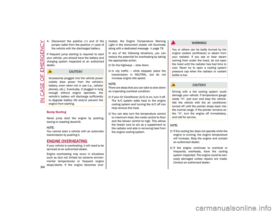
4. Disconnect the positive (+) end of thejumper cable from the positive (+) post of
the vehicle with the discharged battery.
If frequent jump starting is required to start
your vehicle, you should have the battery and
charging system inspected at an authorized
dealer.
Bump Starting
Never jump start the engine by pushing,
towing or coasting downhill.
NOTE:
You cannot start a vehicle with an automatic
transmission by pushing it.
ENGINE OVERHEATING
If your vehicle is overheating, it will need to be
serviced at an authorized dealer.
Engine overheating may occur in situations
such as (but not limited to) extreme environ -
mental temperatures or frequent engine
stops/starts. If the engine becomes over -heated, the Engine Temperature Warning
Light in the instrument cluster will illuminate
along with a dedicated message
Ú
page 79.
In any of the following situations, you can
reduce the potential for overheating by taking
the appropriate action.
On the highways — slow down.
In city traffic — while stopped, place the
transmission in NEUTRAL, but do not
increase engine idle speed.
NOTE:
There are steps that you can take to slow down
an impending overheat condition:
If your Air Conditioner (A/C) is on, turn it off.
The A/C system adds heat to the engine
cooling system and turning the A/C off can
help remove this heat.
You can also turn the temperature control
to maximum heat, the mode control to floor
and the blower control to high. This allows
the heater core to act as a supplement to
the radiator and aids in removing heat from
the engine cooling system.
NOTE:
If the cooling fan does not operate while the
engine is running, the engine temperature
will increase. Stop the engine and contact
an authorized dealer.
If the engine continues to overheat or
frequently overheats, have the cooling
system inspected. The engine could be seri
-
ously damaged unless repairs are made.
Contact an authorized dealer.
CAUTION!
Accessories plugged into the vehicle power
outlets draw power from the vehicle’s
battery, even when not in use (i.e., cellular
phones, etc.). Eventually, if plugged in long
enough without engine operation, the
vehicle’s battery will discharge sufficiently
to degrade battery life and/or prevent the
engine from starting.
WARNING!
You or others can be badly burned by hot
engine coolant (antifreeze) or steam from
your radiator. If you see or hear steam
coming from under the hood, do not open
the hood until the radiator has had time to
cool. Never try to open a cooling system
pressure cap when the radiator or coolant
bottle is hot.
CAUTION!
Driving with a hot cooling system could
damage your vehicle. If temperature gauge
reads “H”, pull over and stop the vehicle.
Idle the vehicle with the air conditioner
turned off until the pointer drops back into
the normal range. If the pointer remains on
the “H”, turn the engine off immediately,
and call for service.
21_GU_OM_EN_USC_t.book Page 204
Page 210 of 280
208
SERVICING AND MAINTENANCE
Correct servicing permits the performance of
the vehicle to be maintained over time, as well
as limited running costs and safeguarding the
efficiency of the safety systems.
SCHEDULED SERVICING
Correct servicing is crucial for guaranteeing a
long life for the vehicle under the best condi-
tions.
For this reason, Alfa Romeo has planned a
series of checks and services for your vehicle
at fixed intervals based on distance and time,
as described in the Scheduled Servicing Plan.
Before each service, it is always necessary to
carefully follow the instructions in the Sched -
uled Servicing Plan (e.g. periodically check
level of fluids, tire pressure, etc.).
Scheduled Servicing is offered by an autho -
rized dealer according to a set time schedule.
If, during each operation, in addition to the
ones scheduled, the need arises for further
replacements or repairs, these may be carried
out with the owner’s explicit consent only.
NOTE:
Scheduled Servicing intervals are required by
the manufacturer. Failure to have them
carried out may invalidate the New Vehicle
Limited Warranty.
You are advised to inform an authorized
dealer of any small operating irregularities
without waiting for the next service.
Periodic Checks
Every month or every 620 miles (1,000 km) or
before long trips check and, if necessary, top
off:
Engine coolant level.
Brake fluid level (if insufficient, see an
authorized dealer as soon as possible).
Windshield washer fluid level.
Tire inflation pressure and condition.
Operation of lighting system (headlights,
direction indicators, hazard warning lights,
etc.).
Operation of windshield washing/wiping
system and positioning/wear of wiper
blades.
Inspect the CV/Universal joints.
Oil consumption of the engine depends on
conditions and driving style. For this reason,
the engine oil level must be checked every
1,860 miles (3,000 km), and top off if neces -
sary; for further information
Ú
page 215.
Heavy Usage Of The Vehicle
If the vehicle is used under one of the following
conditions:
Dusty roads.
Short, repeated journeys less than 4 miles
(7 km) at sub-zero outside temperatures.
Engine often idling or driving long distances
at low speeds or long periods of inactivity.
In the event of a long period of inactivity.
The following checks must be carried out more
often than indicated in the Scheduled
Servicing Plan:
Check cleanliness of hood and liftgate
locks, cleanliness and lubrication of
linkage.
Visually inspect conditions of: engine, trans -
mission, pipes and hoses (exhaust/fuel
system/brakes) and rubber elements
(sleeves/bushes, etc.).
Check battery charge and battery fluid level
(electrolyte).
Visually inspect conditions of the accessory
drive belts.
Check and, if necessary, change engine oil
and replace oil filter.
Check and, if necessary, replace cabin air
filter.
Check and, if necessary, replace air cleaner.
Severe Duty All Models
Change engine oil at 4,000 miles (6,500 km)
if the vehicle is operated in a dusty and
off-road environment or is operated predomi -
nately at idle or only very low engine RPM. This
type of vehicle use is considered Severe Duty.
21_GU_OM_EN_USC_t.book Page 208
Page 211 of 280
209
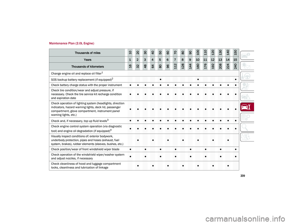
Maintenance Plan (2.0L Engine)
Thousands of miles102030405060708090100110120130140150
Years123456789101112131415
Thousands of kilometers163248648096112128144160176192208224240
Change engine oil and replace oil filter1
SOS backup battery replacement (if equipped)
2●●●
Check battery charge status with the proper instrument
●●●●●●●●●●●●●●●
Check tire condition/wear and adjust pressure, if
necessary. Check the tire service kit recharge condition
and expiration date
●●●●●●●●●●●●●●●
Check operation of lighting system (headlights, direction
indicators, hazard warning lights, deck lid, passenger
compartment, glove compartment, instrument panel
warning lights, etc.)
●●●●●●●●●●●●●●●
Check and, if necessary, top up fluid levels
3●●●●●●●●●●●●●●●
Check engine control system operation (via diagnostic
tool) and engine oil degradation (if equipped)
4●●●●●●●●●●●●●●●
Visually inspect conditions of: exterior bodywork,
underbody protection, pipes and hoses (exhaust, fuel
system, brakes), rubber elements (sleeves, bushes, etc.)
●●●●●●●
Check position/wear of front windshield wiper blade●●●●●●●●
Check operation of the windshield wiper/washer system
and adjust nozzles, if necessary
●●●●●●●●
Check cleanliness of hood and luggage compartment
locks, cleanliness and lubrication of linkage
●●●●●●●
21_GU_OM_EN_USC_t.book Page 209