2021 ALFA ROMEO STELVIO ECU
[x] Cancel search: ECUPage 37 of 280
35
NOTE:
After selecting a heating level, heat will be
felt within a few minutes.
The engine must be running for the heated
seats to operate.
The “minimum” setting is automatically
deactivated once a certain period of time
has elapsed.
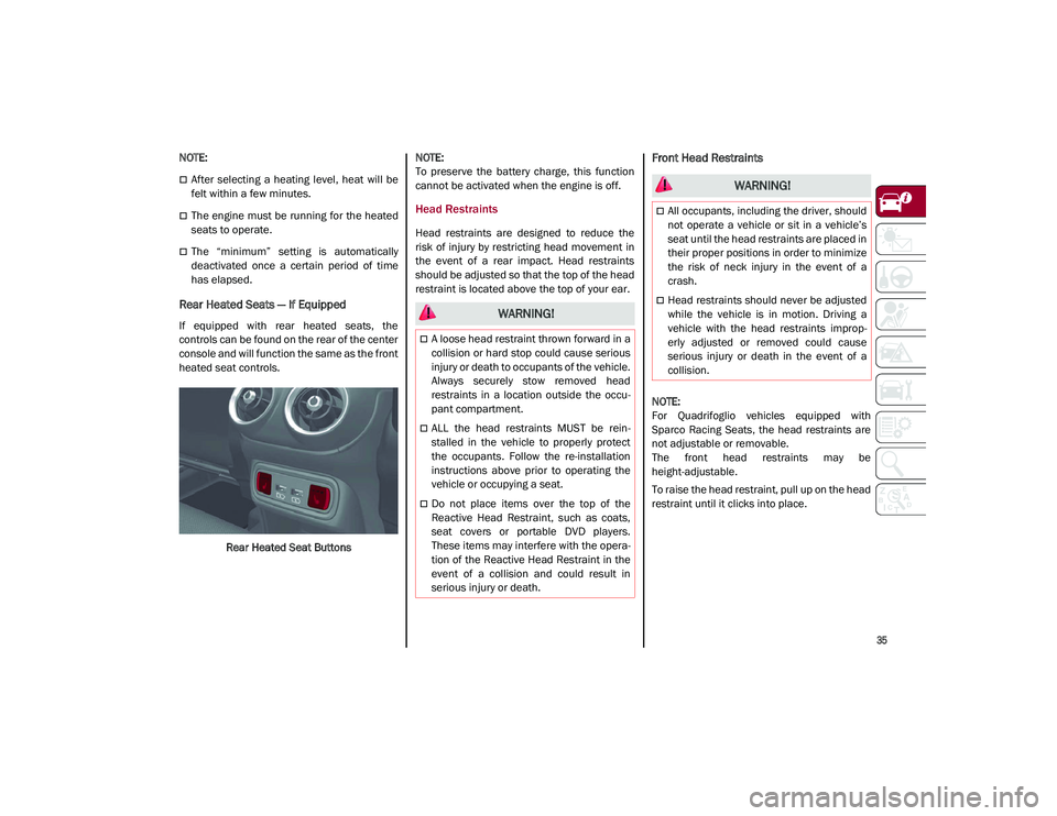
Rear Heated Seats — If Equipped
If equipped with rear heated seats, the
controls can be found on the rear of the center
console and will function the same as the front
heated seat controls.Rear Heated Seat Buttons
NOTE:
To preserve the battery charge, this function
cannot be activated when the engine is off.
Head Restraints
Head restraints are designed to reduce the
risk of injury by restricting head movement in
the event of a rear impact. Head restraints
should be adjusted so that the top of the head
restraint is located above the top of your ear.
Front Head Restraints
NOTE:
For Quadrifoglio vehicles equipped with
Sparco Racing Seats, the head restraints are
not adjustable or removable.
The front head restraints may be
height-adjustable.
To raise the head restraint, pull up on the head
restraint until it clicks into place.
WARNING!
A loose head restraint thrown forward in a
collision or hard stop could cause serious
injury or death to occupants of the vehicle.
Always securely stow removed head
restraints in a location outside the occu
-
pant compartment.
ALL the head restraints MUST be rein -
stalled in the vehicle to properly protect
the occupants. Follow the re-installation
instructions above prior to operating the
vehicle or occupying a seat.
Do not place items over the top of the
Reactive Head Restraint, such as coats,
seat covers or portable DVD players.
These items may interfere with the opera -
tion of the Reactive Head Restraint in the
event of a collision and could result in
serious injury or death.
WARNING!
All occupants, including the driver, should
not operate a vehicle or sit in a vehicle’s
seat until the head restraints are placed in
their proper positions in order to minimize
the risk of neck injury in the event of a
crash.
Head restraints should never be adjusted
while the vehicle is in motion. Driving a
vehicle with the head restraints improp -
erly adjusted or removed could cause
serious injury or death in the event of a
collision.
21_GU_OM_EN_USC_t.book Page 35
Page 39 of 280
37
3. Push the adjustment button and therelease button at the side of the two
supports at the same time.
4. Pull upward on the head restraint to fully remove it.
To reinstall the head restraints, proceed as
follows:
1. Hold down both the adjustment button and release button while placing the head
restraint posts into the holes.
2. Then, reposition the head restraint to the appropriate height for the passengers.
3. Replace the seat back to the appropriate position for passengers.MIRRORS
Automatic Dimming Mirror
The rearview mirror can be adjusted up, down,
left, and right. The mirror should be adjusted
to center on the view through the rear window.
This mirror automatically adjusts for headlight
glare from vehicles behind you.
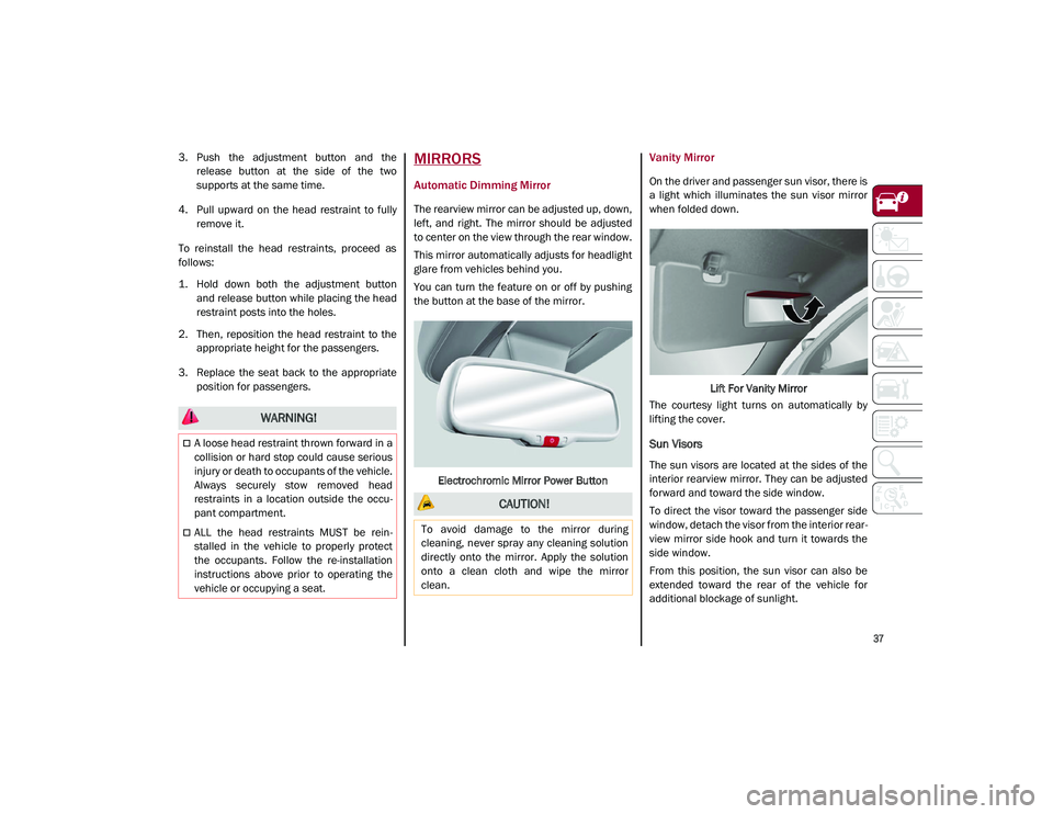
You can turn the feature on or off by pushing
the button at the base of the mirror.
Electrochromic Mirror Power Button
Vanity Mirror
On the driver and passenger sun visor, there is
a light which illuminates the sun visor mirror
when folded down. Lift For Vanity Mirror
The courtesy light turns on automatically by
lifting the cover.
Sun Visors
The sun visors are located at the sides of the
interior rearview mirror. They can be adjusted
forward and toward the side window.
To direct the visor toward the passenger side
window, detach the visor from the interior rear -
view mirror side hook and turn it towards the
side window.
From this position, the sun visor can also be
extended toward the rear of the vehicle for
additional blockage of sunlight.
WARNING!
A loose head restraint thrown forward in a
collision or hard stop could cause serious
injury or death to occupants of the vehicle.
Always securely stow removed head
restraints in a location outside the occu -
pant compartment.
ALL the head restraints MUST be rein -
stalled in the vehicle to properly protect
the occupants. Follow the re-installation
instructions above prior to operating the
vehicle or occupying a seat.
CAUTION!
To avoid damage to the mirror during
cleaning, never spray any cleaning solution
directly onto the mirror. Apply the solution
onto a clean cloth and wipe the mirror
clean.
21_GU_OM_EN_USC_t.book Page 37
Page 41 of 280
39
If the door mirrors were folded using the power
mirror control knob, they can only be returned
to the driving position by moving the knob to
the power folding position again.
NOTE:
The power folding operation can be enabled
only when the vehicle speed is lower than
31 mph (50 km/h).
Outside Automatic Dimming Mirrors — If
Equipped
The outside mirrors will automatically dim for
glare from vehicles behind you. This feature is
controlled by the inside automatic dimming
mirror. The mirrors will automatically adjust for
headlight glare when the inside mirror adjusts.
Heated Mirrors
Push the rear defrost button, located within
the climate controls, to activate the heated
mirrors.
UNIVERSAL GARAGE DOOR
OPENER (HOMELINK®)
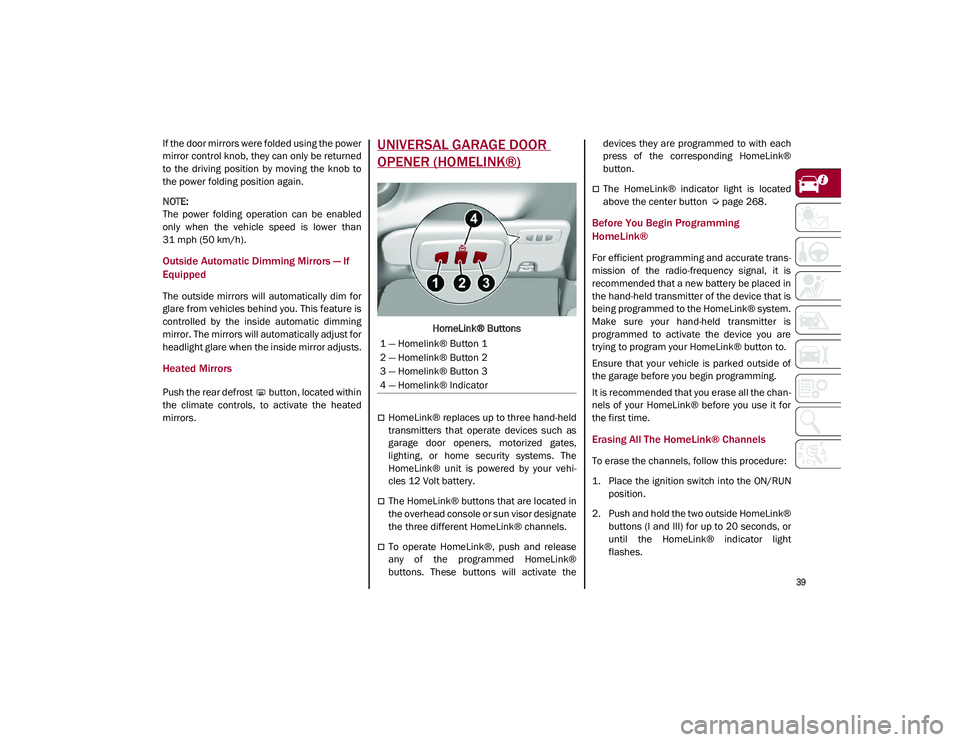
HomeLink® Buttons
HomeLink® replaces up to three hand-held
transmitters that operate devices such as
garage door openers, motorized gates,
lighting, or home security systems. The
HomeLink® unit is powered by your vehi-
cles 12 Volt battery.
The HomeLink® buttons that are located in
the overhead console or sun visor designate
the three different HomeLink® channels.
To operate HomeLink®, push and release
any of the programmed HomeLink®
buttons. These buttons will activate the devices they are programmed to with each
press of the corresponding HomeLink®
button.
The HomeLink® indicator light is located
above the center button
Ú
page 268.
Before You Begin Programming
HomeLink®
For efficient programming and accurate trans -
mission of the radio-frequency signal, it is
recommended that a new battery be placed in
the hand-held transmitter of the device that is
being programmed to the HomeLink® system.
Make sure your hand-held transmitter is
programmed to activate the device you are
trying to program your HomeLink® button to.
Ensure that your vehicle is parked outside of
the garage before you begin programming.
It is recommended that you erase all the chan -
nels of your HomeLink® before you use it for
the first time.
Erasing All The HomeLink® Channels
To erase the channels, follow this procedure:
1. Place the ignition switch into the ON/RUN position.
2. Push and hold the two outside HomeLink® buttons (I and III) for up to 20 seconds, or
until the HomeLink® indicator light
flashes.
1 — Homelink® Button 1
2 — Homelink® Button 2
3 — Homelink® Button 3
4 — Homelink® Indicator
21_GU_OM_EN_USC_t.book Page 39
Page 61 of 280
59
To close the window, pull the window switch
up. To stop the window during Auto-Up opera-
tion, push or pull the window switch again.
Auto-Up Feature With Anti-Pinch Protection
The vehicle is equipped with an anti-pinch
safety device for closing the windows.
If the safety system senses any obstacle while
the window is closing, it will stop the window’s
movement and reverse it, depending on its
position.
This device is also useful if the windows are
activated accidentally by children inside the
vehicle.
The anti-pinch safety function is activated both
during the manual and the automatic opera -
tion of the window.
When the anti-pinch system is activated, the
window closing is immediately interrupted.
Then the window closing is automatically reversed and the window lowers by about
8 inches (20 cm) in relation to the first stop
position. The window cannot be operated
during this time.
NOTE:
In the event of an error, or if the anti-pinch
protection is activated three consecutive
times, the automatic closing operation of the
window will be deactivated. In order to restore
the correct operation of the system, the
window must be lowered.
Power Window System Initialization
If power supply is interrupted, the electric
window automatic operation must be reinitial
-
ized.
To perform the initialization procedure, which
must be done on each door with the doors
closed, manually fully close the window to be
initialized.
Wind Buffeting
Wind buffeting can be described as the
perception of pressure on the ears or a heli -
copter-type sound in the ears. Your vehicle
may exhibit wind buffeting with the windows
down, or the sunroof (if equipped) in certain
open or partially open positions. This is a
normal occurrence and can be minimized. If
the buffeting occurs with the rear windows
open, open the front and rear windows together to minimize the buffeting. If the
buffeting occurs with the sunroof open, adjust
the sunroof opening to minimize the buffeting
or open any window.
POWER SUNROOF — IF
EQUIPPED
Power Sunroof
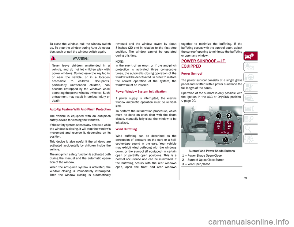
The power sunroof consists of a single glass
panel and is fitted with a power sunshade the
full length of the panel.
Operation of the sunroof is only possible with
the ignition in the ACC or ON/RUN position
Ú
page 20.
Sunroof And Power Shade Buttons
WARNING!
Never leave children unattended in a
vehicle, and do not let children play with
power windows. Do not leave the key fob in
or near the vehicle, or in a location
accessible to children. Occupants,
particularly unattended children, can
become entrapped by the windows while
operating the power window switches. Such
entrapment may result in serious injury or
death.
1 — Power Shade Open/Close
2 — Sunroof Open/Close Button
3 — Vent Open/Close
21_GU_OM_EN_USC_t.book Page 59
Page 62 of 280
GETTING TO KNOW YOUR VEHICLE
60
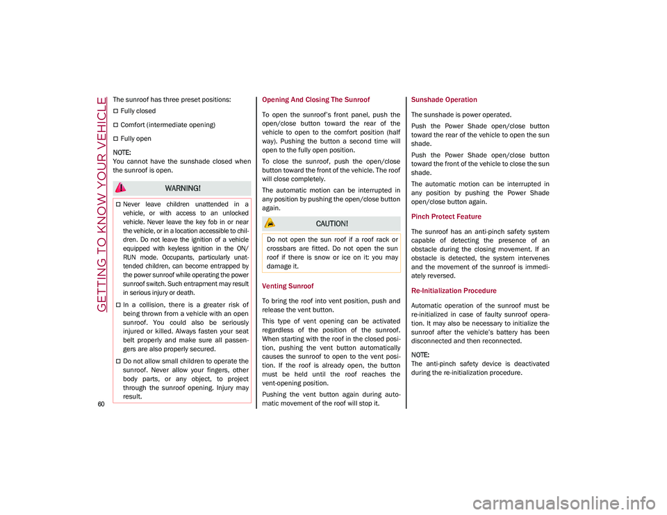
The sunroof has three preset positions:
Fully closed
Comfort (intermediate opening)
Fully open
NOTE:
You cannot have the sunshade closed when
the sunroof is open.
Opening And Closing The Sunroof
To open the sunroof’s front panel, push the
open/close button toward the rear of the
vehicle to open to the comfort position (half
way). Pushing the button a second time will
open to the fully open position.
To close the sunroof, push the open/close
button toward the front of the vehicle. The roof
will close completely.
The automatic motion can be interrupted in
any position by pushing the open/close button
again.
Venting Sunroof
To bring the roof into vent position, push and
release the vent button.
This type of vent opening can be activated
regardless of the position of the sunroof.
When starting with the roof in the closed posi -
tion, pushing the vent button automatically
causes the sunroof to open to the vent posi -
tion. If the roof is already open, the button
must be held until the roof reaches the
vent-opening position.
Pushing the vent button again during auto -
matic movement of the roof will stop it.
Sunshade Operation
The sunshade is power operated.
Push the Power Shade open/close button
toward the rear of the vehicle to open the sun
shade.
Push the Power Shade open/close button
toward the front of the vehicle to close the sun
shade.
The automatic motion can be interrupted in
any position by pushing the Power Shade
open/close button again.
Pinch Protect Feature
The sunroof has an anti-pinch safety system
capable of detecting the presence of an
obstacle during the closing movement. If an
obstacle is detected, the system intervenes
and the movement of the sunroof is immedi -
ately reversed.
Re-Initialization Procedure
Automatic operation of the sunroof must be
re-initialized in case of faulty sunroof opera -
tion. It may also be necessary to initialize the
sunroof after the vehicle’s battery has been
disconnected and then reconnected.
NOTE:
The anti-pinch safety device is deactivated
during the re-initialization procedure.
WARNING!
Never leave children unattended in a
vehicle, or with access to an unlocked
vehicle. Never leave the key fob in or near
the vehicle, or in a location accessible to chil -
dren. Do not leave the ignition of a vehicle
equipped with keyless ignition in the ON/
RUN mode. Occupants, particularly unat -
tended children, can become entrapped by
the power sunroof while operating the power
sunroof switch. Such entrapment may result
in serious injury or death.
In a collision, there is a greater risk of
being thrown from a vehicle with an open
sunroof. You could also be seriously
injured or killed. Always fasten your seat
belt properly and make sure all passen -
gers are also properly secured.
Do not allow small children to operate the
sunroof. Never allow your fingers, other
body parts, or any object, to project
through the sunroof opening. Injury may
result.
CAUTION!
Do not open the sun roof if a roof rack or
crossbars are fitted. Do not open the sun
roof if there is snow or ice on it: you may
damage it.
21_GU_OM_EN_USC_t.book Page 60
Page 67 of 280
65
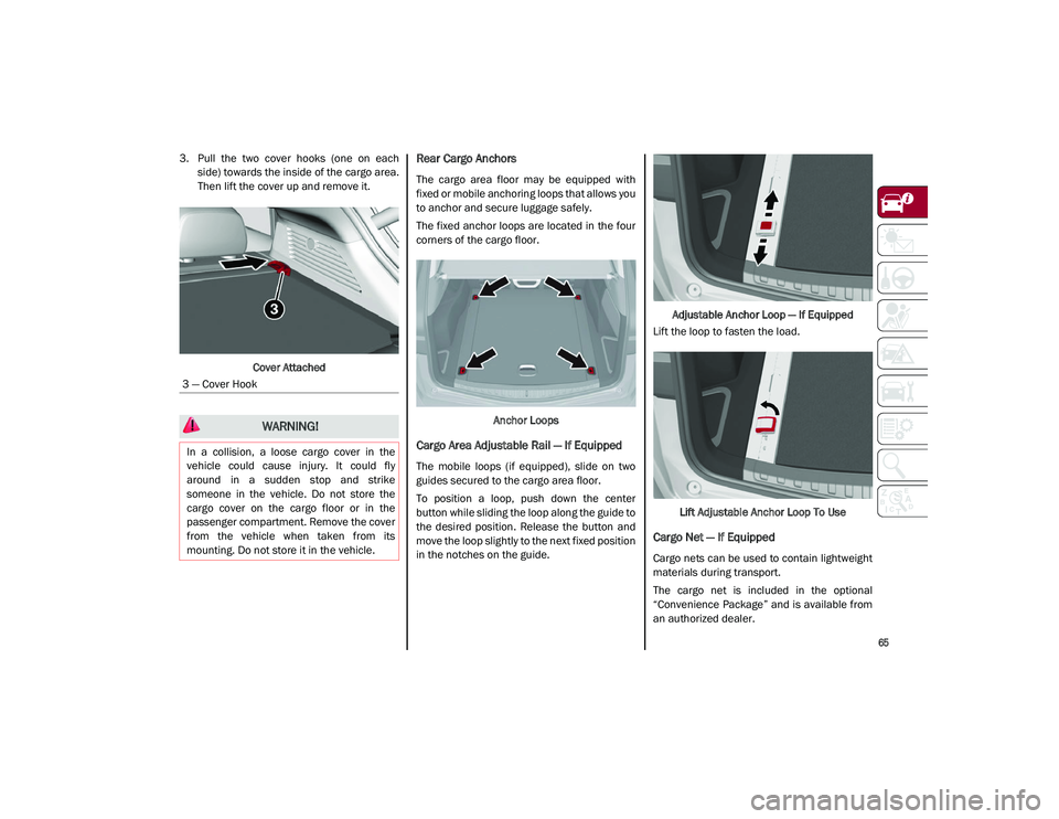
3. Pull the two cover hooks (one on eachside) towards the inside of the cargo area.
Then lift the cover up and remove it.
Cover AttachedRear Cargo Anchors
The cargo area floor may be equipped with
fixed or mobile anchoring loops that allows you
to anchor and secure luggage safely.
The fixed anchor loops are located in the four
corners of the cargo floor. Anchor Loops
Cargo Area Adjustable Rail — If Equipped
The mobile loops (if equipped), slide on two
guides secured to the cargo area floor.
To position a loop, push down the center
button while sliding the loop along the guide to
the desired position. Release the button and
move the loop slightly to the next fixed position
in the notches on the guide. Adjustable Anchor Loop — If Equipped
Lift the loop to fasten the load.
Lift Adjustable Anchor Loop To Use
Cargo Net — If Equipped
Cargo nets can be used to contain lightweight
materials during transport.
The cargo net is included in the optional
“Convenience Package” and is available from
an authorized dealer.
3 — Cover Hook
WARNING!
In a collision, a loose cargo cover in the
vehicle could cause injury. It could fly
around in a sudden stop and strike
someone in the vehicle. Do not store the
cargo cover on the cargo floor or in the
passenger compartment. Remove the cover
from the vehicle when taken from its
mounting. Do not store it in the vehicle.
21_GU_OM_EN_USC_t.book Page 65
Page 84 of 280

GETTING TO KNOW YOUR INSTRUMENT PANEL
82
Automatic Transmission Fluid Overheating
The telltale will illuminate in the case
of transmission overheating, after a
particularly demanding use. In this
case an engine performance limita-
tion is carried out.
Wait for the telltale to turn off with the engine
off or idling.
Audio System Failure
The telltale will illuminate to report a
failure of the audio system.
Contact an authorized dealer as soon as
possible to have the failure eliminated.
Speed Limiter System Failure
While driving, the telltale will illumi -
nate to signal a Speed Limiter
system failure.
Contact an authorized dealer as soon as
possible to have the failure eliminated.
Loose Fuel Filler Cap
Lights up if the fuel tank cap is open
or not properly closed.
Tighten the cap properly.
Electric Park Brake Failure
The telltale will illuminate and a
message will display to signal a
failure in the electric park brake
system.
This failure may partially or completely block
the vehicle because the park brake could
remain activated even if automatically or
manually disengaged using the relevant
controls. In these circumstances, you can
disengage the park brake following the emer -
gency disengagement procedure
Ú
page 90.
If you are still able to drive the vehicle (park
brake is not engaged), drive to the nearest
authorized dealer and remember, when
executing any maneuvers/commands, that
the electric park brake is not operational.
Low Coolant Level — If Equipped
This telltale will illuminate to indicate
that the vehicle coolant level is low.
Service Adaptive Cruise Control (ACC)
System
This light will illuminate when the
ACC is not operating and needs
service.
Contact an authorized dealer to have the
system checked.
Wear On Brake Pads
This light will illuminate when the
brake pads have reached their wear
limit.
Contact an authorized dealer as soon as
possible.
NOTE:
Always use genuine parts or similar because
the Integrated Brake System (IBS) system
could detect anomalies.
Dynamic Drive Control System Failure
The telltale will illuminate to signal a
failure in the dynamic drive control
system.
Windshield Wiper Failure
Signals a windshield wiper failure.
Contact an authorized dealer.
WARNING!
If a failure is present with sharp braking,
the rear wheels may lock and the vehicle
may swerve.
21_GU_OM_EN_USC_t.book Page 82
Page 86 of 280

GETTING TO KNOW YOUR INSTRUMENT PANEL
84
Green Symbols
Headlights
The telltale will illuminate when the
headlights are turned on.
Automatic Headlights
The symbol lights up when the auto-
matic headlights are on.
Stop/Start Operation
The telltale will illuminate in the case
of Stop/Start system intervention
(stopping the engine).
When the engine is restarted, the telltale will
shut off
Ú
page 101.
Cruise Control Activated
The telltale will illuminate when the
Cruise Control system is activated.
Adaptive Cruise Control System — If
Equipped
The symbol comes on when the
Adaptive Cruise Control system is
activated.
Blue Symbols
Automatic High Beam Headlights — If
Equipped
The telltale will illuminate when the
automatic high beam headlights are
activated.
High Beam Headlights
The telltale will illuminate when the
high beam headlights are activated.
ONBOARD DIAGNOSTIC
SYSTEM
Operation
The Onboard Diagnostic system (OBD) carries
out a continuous diagnosis of the components
of the vehicle related to emissions.
It also alerts the driver of when these compo -
nents are no longer in peak condition by
switching on the Engine Check/Malfunc -
tion Indicator warning light on the instrument
panel. The aim of the OBD system (Onboard Diag
-
nostic) is to:
Monitor the efficiency of the system
Indicate an increase in emissions
Indicate the need to replace damaged
components
The vehicle also has a connector, which can
interface with appropriate tools, that makes it
possible to read the error codes stored in the
electronic control units together with a series
of specific parameters for engine operation
and diagnosis. This check can be carried out
by an authorized dealer.
NOTE:
After eliminating a fault, to check the system
completely, an authorized dealer is obliged to
run tests and, if necessary certain road tests.
Onboard Diagnostic System (OBD II)
Cybersecurity
Your vehicle is required to have OBD II and a
connection port to allow access to information
related to the performance of your emissions
controls. Authorized service technicians may
need to access this information to assist with
the diagnosis and service of your vehicle and
emissions system.
21_GU_OM_EN_USC_t.book Page 84