Page 129 of 264

IN CASE OF EMERGENCY127
3. Remove the two (2) 17mm tail light
assembly fasteners.
4. Disconnect the tail light harness connector and remove tail light assembly from the
vehicle.
5. Remove the tail/stop, turn signal, backup and rear side marker bulb/socket by
rotating counterclockwise.
6. Remove the bulb and replace as needed.
7. Reinstall bulb/socket and rotate clockwise to lock in place.
8. Reinstall lamp.
Replacing Interior Bulbs
Cargo Lamp
1. Using a suitable tool, remove either the lamp above the back door or the sliding
door lamp as needed and disconnect it. Rear Cargo Lamp Bulb Access
2. Using a suitable tool, pull open the metal bulb access on the back of the housing.
Cargo Lamp Bulb Location 3. Remove and install the replacement bulb.
4. Close the bulb access, connect the lamp
and install the lamp into place.
Dome Lamps
1. Using a suitable tool, insert the tip at thelocation shown and press inward to the
lamp to relieve the spring tension. This will
allow you to easily drop the dome lamp
assembly from its bracket and disconnect
the lamp.
Dome Lamp Assembly Location
1 — Spring Tension Relief Access
2 — Dome Lamp Assembly
6
20_VF_OM_EN_US_t.book Page 127
Page 130 of 264

128IN CASE OF EMERGENCY
(Continued)
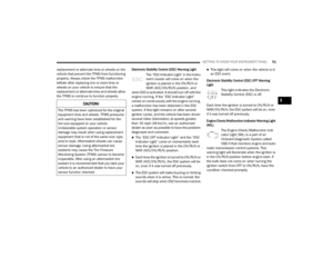
2. Using a suitable tool, flex the housing to lift
the light pod cover away from the unit.
Dome Lamp Light Pod Cover
3. Remove and replace the bulbs as needed.
Dome Lamp Light Bulbs 4. Close the housing cover making sure it
snaps together properly and connect the
lamp.
5. Install overhead console into place making sure to seat the assembly’s forward end
first and then snapping it flush so that the
tension spring is fully seating in the housing.
FUSESUnderhood Fuses
The Front Power Distribution Center is located
on the driver’s side of the engine compartment.
To access the fuses, remove the cover.
Front Power Distribution Center
The ID number of the electrical component
corresponding to each fuse can be found on the
back of the cover.WARNING!
When replacing a blown fuse, always use
an appropriate replacement fuse with the
same amp rating as the original fuse. Never
replace a fuse with another fuse of higher
amp rating. Never replace a blown fuse with
metal wires or any other material. Do not
place a fuse inside a circuit breaker cavity
or vice versa. Failure to use proper fuses
may result in serious personal injury, fire
and/or property damage.
Before replacing a fuse, make sure that the
ignition is off and that all the other services
are switched off and/or disengaged.
If the replaced fuse blows again, contact an
authorized dealer.
If a general protection fuse for safety
systems (air bag system, braking system),
power unit systems (engine system, trans -
mission system) or steering system blows,
contact an authorized dealer.
WARNING!
(Continued)
20_VF_OM_EN_US_t.book Page 128
Page 131 of 264

IN CASE OF EMERGENCY129
CavityMaxi Fuse Mini Fuse Description
F0140 Amp Orange – Electronic Stability Control (ESC) Pump
F02 20 Amp Yellow (3.6 Gasoline
Engine) –
Starter Relay 3.6L (3.6 Gasoline Engine)
F04 50 Amp Red (3.6 Gasoline
Engine) –
Secondary Power Distribution Center (PDC) (Trans
Power Relay, Vacuum Pump, KL30 for the Shifter
Transmission Module [STM]) (3.6 Gasoline Engine)
F06 40 Amp Orange (non A/C)
60 Amp Blue (A/C) –
Engine Cooling Fan - 2nd Speed
F07 50 Amp Red (non A/C)
60 Amp Blue (A/C) –
Engine Cooling Fan - 1st Speed
F08 40 Amp Orange – Passenger Compartment Blower
F09 – 15 Amp Blue Rear Power Outlet
F10 – 15 Amp Blue Horn
F14 – 20 Amp Yellow Power Outlet
F15 – 7.5 Amp Brown USB Charger
F16 – 7.5 Amp Brown KL15 Shifter Transmission Module (STM) (3.6), KL15
Starter Relay Coil (3.6 Gasoline Engine)
F17 – 20 Amp Yellow Engine Control Module (ECM), Injectors (3.6 Gasoline
Engine)
F18 – 7.5 Amp Brown KL30 Engine Control Module (ECM), KL30 Main Relay
Coil (3.6 Gasoline Engine)
F19 – 7.5 Amp Brown A/C Compressor — If Equipped
6
20_VF_OM_EN_US_t.book Page 129
Page 132 of 264
130IN CASE OF EMERGENCY
Front PDC Additional Fuses
The additional fuse box is located inside the
front PDC Box.
Front Power Distribution Center Additional Fuses
F20
– 30 Amp Green Windshield Wiper
F21 – 15 Amp Blue Fuel Pump
F22 – 20 Amp Yellow Engine Control Module (ECM), Ignition Coils (3.6
Gasoline Engine)
F23 – 20 Amp Yellow Electronic Stability Control (ESC) Valves
F24 – 7.5 Amp Brown KL15 Vacuum Pump Relay Coil (3.6 Gasoline Engine) —
If Equipped
F30 – 15 Amp Blue Heated Mirrors
CavityMaxi Fuse Mini Fuse Description
CavityMini Fuse Description
F6120 Amp YellowVacuum Pump (3.6 Gasoline Engine)
F62 30 Amp GreenTransmission Power RELE (3.6 Gasoline Engine)
F66 5 Amp BeigeShifter Transmission Module (STM) (3.6 Gasoline Engine)
20_VF_OM_EN_US_t.book Page 130
Page 133 of 264
IN CASE OF EMERGENCY131
Interior Fuses
The interior fuse panel is part of the Body
Control Module (BCM) and is located on the
driver's side under the instrument panel.
Fuse PanelFuse Panel Cavity Locations
CavityMini Fuse Description
F315 Amp BeigeINT/A
F34 7.5 Amp BrownClearance Lights
F36 15 Amp Blue+30 (ACM – TPCU – RRM – DLC)
F37 5 Amp BeigeINT (BRAKE NO – IPC)
F38 15 Amp BlueCentral Locking
F42 5 Amp BeigeINT (BSM – SAS – BRAKE NC)
F43 20 Amp YellowBi-Directional Washer Pump
F47 20 Amp YellowDriver Power Window
F48 20 Amp YellowPassenger Power Window
F49 5 Amp BeigeINT (PAM – CCS – RRM – ECM)
F50 7.5 Amp BrownINT (ORC)
F51 5 Amp BeigeINT (REAR CAMERA-AUX)
6
20_VF_OM_EN_US_t.book Page 131
Page 134 of 264
132IN CASE OF EMERGENCY
Right Central Pillar Fuses
The right central pillar fuse panel is located on
the interior side at the base of the passenger
side B pillar.
Fuse Panel LocationFuse Panel
F53
5 Amp Beige+30 (IPC) + FTM
F92 7.5 Amp BrownLeft Fog Lamp
F93 7.5 Amp BrownRight Fog Lamp
CavityMini Fuse Description
F817.5 Amp BrownSeat Heater
F83 20 Amp Yellow
Rear Left Windows Heater
F84 20 Amp YellowRear Right Windows Heater
F86 20 Amp YellowAuxiliary Switch (From Battery) — If Equipped
F87 20 Amp YellowAuxiliary Switch (From Ignition) — If Equipped
20_VF_OM_EN_US_t.book Page 132
Page 135 of 264

IN CASE OF EMERGENCY133
JACKING AND TIRE CHANGING Jack Location
The jack and jack tools are stored under the
front passenger seat in a box, or next to or
behind the driver seat in a tool bag. The box and
the tool bag contain the same items.
Jack Kit Location
To release the jack kit for it’s storage location,
turn the lock knob a quarter turn counterclock -
wise to the unlock position. Lock Knob
To open the jack kit container, you must push
the container’s release to separate the top and
bottom.
Container ReleaseWARNING!
Do not attempt to change a tire on the side
of the vehicle close to moving traffic. Pull
far enough off the road to avoid the danger
of being hit when operating the jack or
changing the wheel.
Being under a jacked-up vehicle is
dangerous. The vehicle could slip off the
jack and fall on you. You could be crushed.
Never put any part of your body under a
vehicle that is on a jack. If you need to get
under a raised vehicle, take it to a service
center where it can be raised on a lift.
Never start or run the engine while the
vehicle is on a jack.
The jack is designed to be used as a tool for
changing tires only. The jack should not be
used to lift the vehicle for service purposes.
The vehicle should be jacked on a firm level
surface only. Avoid ice or slippery areas.
CAUTION!
Do not force lock knob over limit. Damage to
lock knob may occur.
1 — Unlock Position
2 — Lock Position
6
20_VF_OM_EN_US_t.book Page 133
Page 136 of 264
134IN CASE OF EMERGENCY
Jacking Tools
Spare Tire Removal
1. Remove the spare tire before attempting to
jack up the vehicle. Attach the lug bolt
adapter to the winch extension and insert it
into the winch mechanism. Jack Tools
Winch Location The winch mechanism is located under the
rear of the vehicle to the right of the spare
tire.
Winch Extension
2. Rotate the wheel wrench handle counter -
clockwise until the spare tire is on the
ground with enough cable slack to allow you
to pull it out from under the vehicle.
1 — Tow Eye
2 — Wrench Handle
3 — Lug Bolt Adaptor
4 — Jack
5 — Reversible Tool
6 — Tool Handle
7 — Winch Extension1 — Wrench Handle
2 — Lug Bolt Adapter
3 — Winch Extension
20_VF_OM_EN_US_t.book Page 134