Page 105 of 400

8V2012721BK
High-voltage system
> Close the door.
> After charging, you can place the vehicle charg-
ing connector (6) > page 101, fig. 96 in the
holder on the charging dock door > fig. 98.
Removing the charging system from the
charging dock
> Open the door on the charging dock.
> Remove the power cable connector from the
socket in the charging dock.
> Unwrap the cable from the adapter ().
> To loosen the control unit from the holder,
press the release tabs above the control unit in
the direction of the arrow > fig. 99.
G) Tips
— Always keep the door on the charging dock
closed.
— Do not place any objects on the door or the
charging dock.
Charging clip
Applies to: vehicles with plug-in hybrid drive and charging clip
[RAZ-0075|
=O)
.
t
4—_(+)
Fig. 100 Charging clip: charging system connected
Connecting the charging system to the
charging clip
> First insert the control unit in the bottom tabs
on the charging clip and then into the upper
tabs.
> Push the control unit in the direction of the ar-
row toward the rear > fig. 100 and let it lock in-
to place.
> Wrap the extra cable length around the charg-
ing connector mount ().
> Plug the power cable into the socket @).
> After charging, you can hook the vehicle charg-
ing connector G) > page 101, fig. 96 to the
charging connector mount @) © fig. 100.
Removing the charging system from the
charging clip
> Remove the power cable connector from the
socket (2).
> Unwind the cable from the charging connector
mount (2).
> To loosen the control unit from the bracket,
push the locking mechanism@) upward
=> fig. 100.
Applies to: vehicles with plug-in hybrid drive
rT re} t g
> e 3
Fig. 101 Ski sack
Store the charging system and the special charg-
ing cable* in the bag before transporting.
> Always position the bag on the left side of the
luggage compartment > page 62.
> Secure the flat hook to the tie-down near the
edge of the cargo floor.
> Secure the carabiner hook at the tie-down near
the rear seat backrest.
Z\ WARNING
— If the vehicle charging cable is not secured
or positioned correctly, it can slide out of
place and endanger vehicle occupants when
braking, when changing directions, or in an
accident.
— Never transport the Audi charging system or
the special charging cable* without securing
them. >
103
Page 106 of 400

High-voltage system
— Store the Audi charging system or the spe-
cial charging cable* in the ski sack in the
luggage compartment.
— Always transport the ski sack in the luggage
compartment and never in the passenger
compartment (for example, on the seats or
in front of them).
©) Note
Always lift or transport the Audi charging sys-
tem as an entire unit and never by the cables.
Charging time
Applies to: vehicles with plug-in hybrid drive
The length of the charging process using the Audi
charging system may vary based on the following
factors:
— The sockets that are used (household or indus-
trial* sockets)
— The system voltage and current strength that
are specific to a country
— The value set for the charging power level on
the control unit (50% or 100%).
— Fluctuations in the system voltage
— The temperature outside the vehicle
— The temperature of the high-voltage battery
— Settings for the climate control inside the vehi-
cle
— Current capacity of the charging connector
— Whether the ignition is on or off
Example charging times
Connection Charging time at
100% charge
Household socket
(100 V, 10 A)
approximately 10
hours
Household socket
(120 V, 10 A)
approximately 8.2
hours
Household socket
(220 V, 8A)
approximately 5.2
hours
Household socket
(230 V, 10 A)
approximately 3.8
hours
Industrial socket (200 V,
16 A)
approximately 2.3
hours
104
Connection Charging time at
100% charge
Industrial socket (220 V, | approximately 2.3
16 A) hours
Industrial socket (230 V, | approximately 2.3
16 A) hours
Industrial socket (240 V, | approximately 2.3
16 A) hours
@ Tips
— Multiple versions of charging cables are of-
fered due to the different power supply sys-
tems in different countries. The maximum
charging power may potentially be unavaila-
ble because of this. Contact an authorized
Audi dealer or authorized Audi Service Fa-
cility for more information.
— Charging may take longer when tempera-
tures are extremely high or low.
—The charging time at public charging sta-
tions may vary from the times given in the
table > table on page 104.
Before charging
Applies to: vehicles with plug-in hybrid drive
B8V-0447
Fig. 103 Radiator grille: charging port cap
Page 107 of 400

8V2012721BK
High-voltage system
> Unlock the vehicle if necessary > page 25.
> Make sure that the selector lever is in the “P”
position, the parking brake is set, and drive
ready mode is switched off > page 71.
> Turn the lock until it is vertical to open the cov-
er on the charging unit > fig. 102.
> Slide the cover carefully to the side if necessary.
> Remove the lock on the charging port
> fig. 103.
» Insert the plug @) or @) into the socket
=> page 101, fig. 96.
> Plug the vehicle charging connector ()
=> page 101, fig. 96 into the vehicle charging
port > fig. 103. The charging process starts au-
tomatically if no charging timer is set.
@) Tips
Remove ice and snow from the cover using a
hand brush and solvent-free deicing spray.
Audi e-tron compact
charging system
Charging overview
Applies to: vehicles with Audi e-tron compact charging sys-
tem
RAZ-0077,
unit
Fig. 105 Charging unit: vehicle charging connection and
button module
The charging unit is located behind the Audi rings
on the front of the vehicle.
@ ___|On/Off button ®, charging power lev-
el and LED
@ __ | Status LED:
a Power supply/household
connection
& | Vehicle
0 Control panel
® © [Reset
@ __ |Charging timer button
© __ |Status LED
© __ |Immediate charging button
The meaning of the different status displays for
the charging system and the vehicle can be found
under > page 107.
(i) Tips
— The device runs a self test after power has
been restored to the control unit. If a self
test is successful, all indicator lights will il-
luminate green for two seconds.
— The vehicle cannot be started if a charging
connector is connected.
Cee Testis)
Applies to: vehicles with plug-in hybrid drive
You can switch between the immediate charging
© and charging timer @) options > page 105,
fig. 105 during the charging process if a charging
timer has been set. Press the desired button to
do this > page 105, fig. 105.
Immediate charging
To start the charging process immediately, press
the button © % page 105, fig. 105. The LED in
the button will turn on.
105
>
Page 108 of 400

High-voltage system
Setting the charging timer
You can delay the charging time with the charg-
ing timer in the Infotainment system )). You can
set two different timers.
> If a timer has been set, press the button @)
=> page 105, fig. 105. The LED in the button
will turn on.
> To set a charging timer, select: [MENU] button >
Vehicle > left control button > Charge > right
control button > Program timer.
> Select Individual timer or Repeat timer.
> Set the departure time, the date or day of the
week.
> You can specify a preferred charging time with
the charging timer, for example if you would
like to use the off-peak rate.
> You can activate the auxiliary air conditioning
with the charging timer while charging by se-
lecting Air conditioning with the control knob.
AV appears in the box. This activation is sepa-
rate from the Infotainment system settings in
the climate control menu > page 68.
> Press the [BACK] button.
> To activate the desired timer, confirm the set-
ting with the control knob. A ¥ appears in the
box.
@ Tips
— Auxiliary climate control is powered electri-
cally if you select climate control using the
charging timer. This may also be used in
confined spaces such as garages.
— Using the auxiliary climate control while
charging can also reduce the charge level of
the high-voltage battery.
—The charging process can be interrupted at
any time. Press the active button on the ve-
hicle to do this > page 105, fig. 105.
— The climate control output while charging
depends on the capacity of the electrical
connection. Additional information on cli-
mate control can be found under > page 68.
D_ Not available in all Infotainment systems.
106
Setting the charging power level
Applies to: vehicles with plug-in hybrid drive
The control unit automatically recognizes the
voltage and the available current strength. You
can set whether you would like to charge with full
or reduced charging power. The last setting that
was selected will be saved and used again the
next time the vehicle is charged. If multiple
items are connected to the power circuit, the
charging current may be reduced when charging
at a power outlet. This can help to prevent the
electrical equipment from overheating.
Before charging, always check if the charging
power setting that was selected last is still suita-
ble.
> To set the charging power level, press and hold
the @ button @ > page 105, fig. 104 for at
least two seconds.
After the charging power level is set, the status
LEDs ©, iand {) will flash green one time. The
selected value (50% or 100%) is displayed on the
left or right side of the ® button.
Name lee ale]
Applies to: vehicles with plug-in hybrid drive
After
completing the charging or climate control
process, the vehicle enters a sleep mode. No dis-
plays are visible on the charging unit during this
period. Always remove the vehicle charging con-
nector first after charging.
The vehicle charging connector is locked during
and after charging. You must unlock the connec-
tor to remove it.
Unlocking the vehicle charging connector
when the vehicle is locked
> Unlock the vehicle. The connector will unlock
for 30 seconds.
> Remove the connector.
> If the connector is not removed within 30 sec-
onds, it will lock again automatically.
Page 109 of 400

8V2012721BK
High-voltage system
Deactivating sleep mode
> Unlock the vehicle > page 25. Or
> Open the driver's door. Or
> Press the button © > page 105, fig. 105.
Unlocking the vehicle charging connector
when the vehicle is unlocked
> If necessary, deactivate sleep mode.
> Press the button with the illuminated LED @) or
© > page 105, fig. 105. Or
> Press the {@ button in the driver's door
= page 29, fig. 22 or the & button on the re-
mote control key.
> The connector will unlock for 30 seconds.
> Remove the connector.
> If the connector is not removed within 30 sec-
onds, it will lock again automatically.
Closing the charging unit
> Put the cap back on the charging port
=> page 104, fig. 103.
> Carefully slide the cover back in its original po-
sition.
> Turn the lock to the horizontal position
=> page 104, fig. 102.
@) Note
If you drive with an open charging unit, both
the cover and the electronics installed behind
it could be damaged.
G) Tips
The instrument cluster will indicate if the
charging unit is open while driving. Check be-
fore every drive after charging if the cover is
locked.
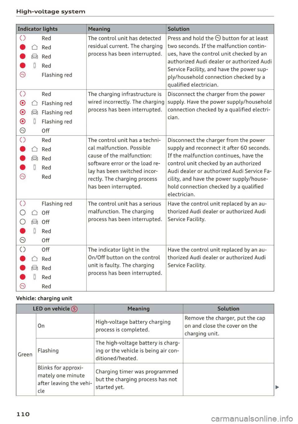
Semele
Applies to: vehicles with plug-in hybrid drive
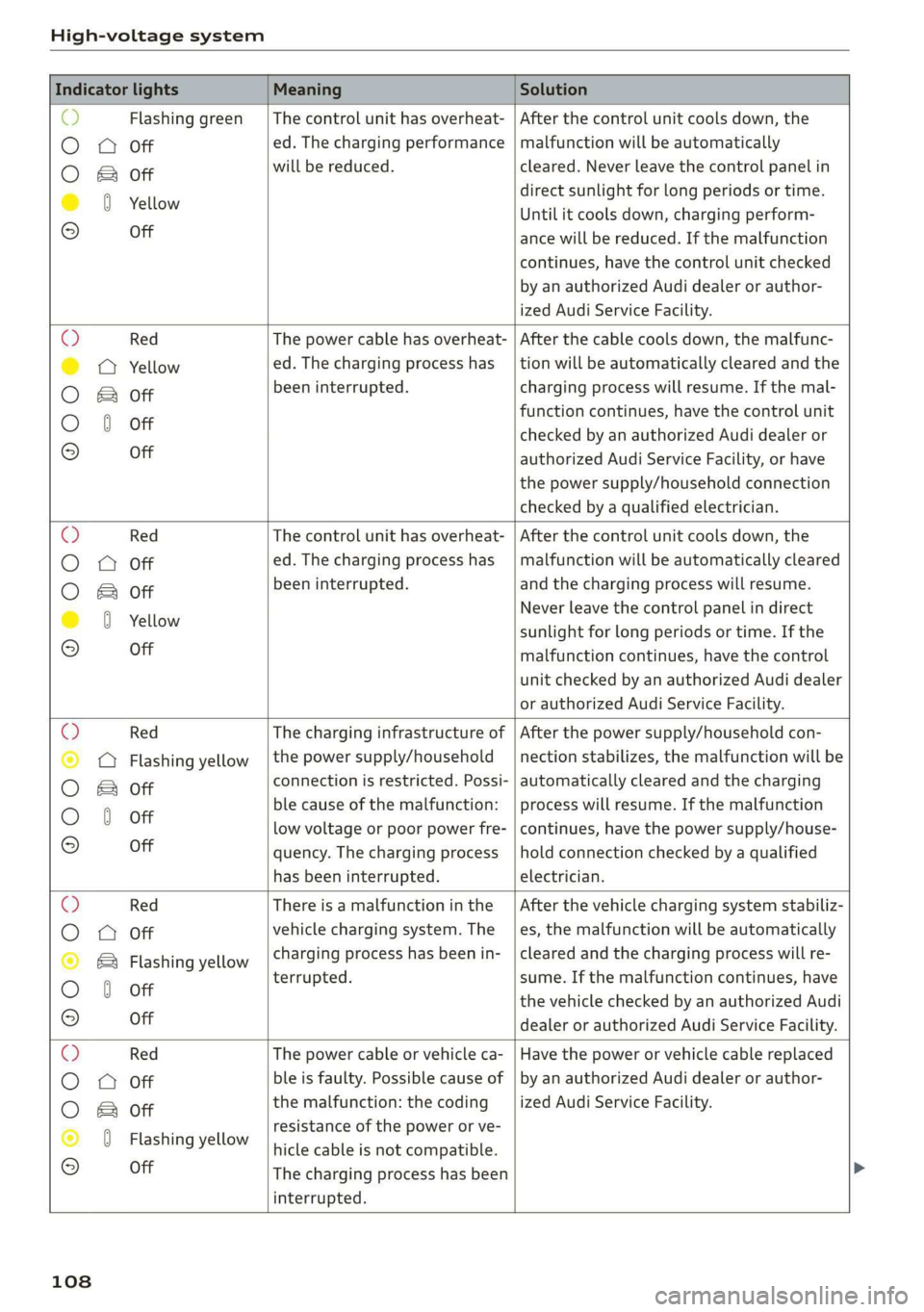
You can check the mode status using the LED on
the control unit @or @) > page 105, fig. 104,
Control panel: status and error displays
and the status LED on the vehicle G) > page 105,
fig. 105
Indicator lights Meaning Solution
© Green The charger is ready to charge, | Starting the charging process
O 0 Off but is not charging. => page 105.
O B&B off
O 0 of
9 Off
c) Flashing green __| The vehicle is being charged
O O off with the ground conductor
O Bor monitor activated.
O 0 Off
9 Off
Sy Flashing green _| The power cable has overheat- | After the cable cools down, the malfunc-
©) a Yellow ed. Possible cause of the mal- | tion will be automatically cleared. Until it
O B otf function: a multi-phase socket | cools down, charging performance will be
O 6 off is being used in single:phase reduced. If the malfunction continues,
mode. The charging perform- | have the power supply/household con-
© Off ance will be reduced. nection checked by a qualified electrician.
107
Page 110 of 400

High-voltage system
Indicator lights Meaning Solution
Q Flashing green |The control unit has overheat- | After the control unit cools down, the
O 0 off ed. The charging performance | malfunction will be automatically
will be reduced. cleared. Never leave the control panel in
O B Of P
direct sunlight for long periods or time.
© 1 Yeltow Until it cools down, charging perform-
9 Off ance will be reduced. If the malfunction
continues, have the control unit checked
by an authorized Audi dealer or author-
ized Audi Service Facility.
O Red The power cable has overheat- | After the cable cools down, the malfunc-
© © Yellow ed. The charging process has __| tion will be automatically cleared and the
been interrupted. charging process will resume. If the mal-
O & off
O 6 of function continues, have the control unit
checked by an authorized Audi dealer or
© Off authorized Audi Service Facility, or have
the power supply/household connection
checked by a qualified electrician.
O Red The control unit has overheat- | After the control unit cools down, the
O QO Off ed. The charging process has__| malfunction will be automatically cleared
been interrupted. and the charging process will resume.
O & Off
@ 0 Yew Never leave the control panel in direct
evo sunlight for long periods or time. If the
© Off malfunction continues, have the control
unit checked by an authorized Audi dealer
or authorized Audi Service Facility.
© Red The charging infrastructure of | After the power supply/household con-
© @ Flashing yellow |the power supply/household | nection stabilizes, the malfunction will be
connection is restricted. Possi- | automatically cleared and the charging
O & off
O 6 of ble cause of the malfunction: | process will resume. If the malfunction
low voltage or poor power fre- | continues, have the power supply/house-
© Off quency. The charging process | hold connection checked by a qualified
has been interrupted. electrician.
O Red There is a malfunction inthe | After the vehicle charging system stabiliz-
O 0 Off vehicle charging system. The | es, the malfunction will be automatically
: charging process has beenin- | cleared and the charging process will re-
© & Flashing yellow ging ging
O 0 of terrupted. sume. If the malfunction continues, have
the vehicle checked by an authorized Audi
© Off dealer or authorized Audi Service Facility.
O Red The power cable or vehicle ca- | Have the power or vehicle cable replaced
O Q Off ble is faulty. Possible cause of | by an authorized Audi dealer or author-
the malfunction: the coding ized Audi Service Facility.
O B&B off
. resistance of the power or ve-
© 0 Flashing yellow hicle cable is not compatible.
9 Off
The charging process has been
interrupted.
108
Page 111 of 400

8V2012721BK
High-voltage system
Indicator lights Meaning Solution
© Red There is a malfunction inthe | End the charging process at the vehicle
O O off vehicle charging system. The | and remove the vehicle cable from the ve-
@ B Red charging process has been in- | hicle charging port. Disconnect the charg-
O 6 of terrupted. er from the power supply and reconnect it
after 60 seconds. Restart the charging
9 Off process > page 105. If the malfunction
continues, have the vehicle checked by an
authorized Audi dealer or authorized Audi
Service Facility.
O Red There is an overvoltage inthe | Disconnect the charger from the power
© CQ Flashing red charging infrastructure of the | supply and reconnect it after 60 seconds.
power supply/household con- | If the malfunction continues, have the
O & off
O 6 off nection. The charging process | power supply/household connection
© has been interrupted. checked by a qualified electrician.
Off
© Red The control unit has atechni- | Disconnect the charger from the power
O 0 Off cal malfunction. The charging | supply and reconnect it after 60 seconds.
O Bot process has been interrupted. |If the malfunction continues, have the
@ 0 Red control unit checked by an authorized
© Audi dealer or authorized Audi Service Fa-
9 Off cility.
© Red The control unit has atechni- | Disconnect the charger from the power
O 0 off cal malfunction (self-test supply and reconnect it after 60 seconds.
O Bot failed). The charging process _ | If the malfunction continues, have the
© 6 Flashi d has been interrupted. control unit checked by an authorized
asning re Audi dealer or authorized Audi Service Fa-
© Off cility.
© Red The charging infrastructure of | Have the control unit checked by an au-
@ CO Red the power supply/household | thorized Audi dealer or authorized Audi
@ & Red connection is insufficient: the | Service Facility, and have the power sup-
O 6 of ground conductor is interrupt- | ply/household connection checked by a
ed or not present. The ground | qualified electrician. Do not use the pow-
9 Off conductor monitor has inter- | er supply/household connector until the
rupted the charging process. | malfunction is corrected.
© Red The indicator light in the reset | Have the control unit replaced by an au-
@ OC Red button on the control unit is | thorized Audi dealer or authorized Audi
@ B& Red faulty. The charging process _| Service Facility.
@ © Red has been interrupted.
e
9 Off
109
Page 112 of 400

High-voltage system
Indicator lights Meaning Solution
O Red The control unit has detected | Press and hold the © button for at least
@ X Red residual current. The charging | two seconds. If the malfunction contin-
@ EB Red process has been interrupted. | ues, have the control unit checked by an
@ © Red authorized Audi dealer or authorized Audi
€ / Service Facility, and have the power sup-
9 Flashing red ply/household connection checked by a
qualified electrician.
© Red The charging infrastructure is | Disconnect the charger from the power
© Q Flashing red wired incorrectly. The charging | supply. Have the power supply/household
© & Flashing red process has been interrupted. | connection checked by a qualified electri-
© § Flashing red eas
9 Off
O Red The control unit has a techni- | Disconnect the charger from the power
@ CX Red cal malfunction. Possible supply and reconnect it after 60 seconds.
@ EB Red cause of the malfunction: If the malfunction continues, have the
@ 0 Red software error or the load re-_ | control unit checked by an authorized
. lay has been switched incor- _| Audi dealer or authorized Audi Service Fa-
9 Red rectly. The charging process cility, and have the power supply/house-
has been interrupted. hold connection checked by a qualified
electrician.
O Flashing red The control unit has a serious | Have the control unit replaced by an au-
O 0 off malfunction. The charging thorized Audi dealer or authorized Audi
O Bot process has been interrupted. | Service Facility.
@ @ Red
9 Off
© Off The indicator light in the Have the control unit replaced by an au-
@ C Red On/Off button on the control | thorized Audi dealer or authorized Audi
@ B Red unit is faulty. The charging Service Facility.
@ 0 Red process has been interrupted.
e
© Red
Vehicle: charging unit
LED on vehicle G) Meaning Solution
. . Remove the charger, put the cap
On High voltage battery charging on and close the cover on the
process is completed. . .
charging unit.
The high-voltage battery is charg-
isan Flashing ing or the vehicle is being air con-
ditioned/heated.
Blinks for approxi-
mately one minute
after leaving the vehi-
cle
started yet.
Charging timer was programmed
but the charging process has not
110