Page 361 of 400
8V2012721BK
Emergency assistance
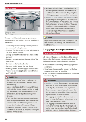
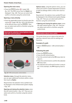
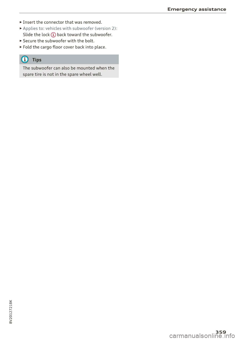
> Insert the connector that was removed.
> Applies to: vehicles with subwoofer (version 2):
Slide the lock @ back toward the subwoofer.
> Secure the subwoofer with the bolt.
> Fold the cargo floor cover back into place.
The subwoofer can also be mounted when the
spare tire is not in the spare wheel well.
359
Page 362 of 400

Fuses and bulbs
Fuses and bulbs
Fuses
(ener aye mates
Fuse color identification
Fig. 280 Left side of the engine compartment: fuse cover
A fuse that has blown will have metal strips that
have burned through.
The fuses are located behind a cover in the steer-
ing column area > fig. 279 or under a cover on
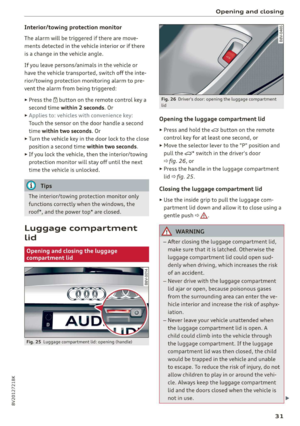
the left side of the engine compartment
> fig. 280.
> Switch the ignition and all electrical equipment
off.
> Check the following table to see which fuse be-
longs to the equipment > page 361.
> Remove the cover.
> Remove the plastic clip from the fuse panel
cover in the engine compartment > fig. 280.
> Remove the fuse using the plastic clamp.
> Replace the blown fuse with a fuse that has the
same amp rating.
>» Reinsert the cover.
360
Color Current rating
in amps
Black a
Purple 3
Light brown 5
Brown 15
Red 10
Blue 15
Yellow 20
White or transparent [25
Green 30
Orange 40
5| | A\ WARNING
Do not repair fuses and never replace a blown
fuse with one that has a higher amp rating.
This can cause damage to the electrical sys-
tem and increases the risk of fire.
(!) Note
If a new fuse burns out again shortly after you
have installed it, have the electrical system
checked as soon as possible by an authorized
Audi dealer or authorized Audi Service Facili-
ty.
@ Tips
— The following table does not list fuse loca-
tions that are not used.
— Some of the equipment listed in the follow-
ing tables applies only to certain model ver-
sions or certain optional equipment.
Page 363 of 400

8V2012721BK
Fuses and bulbs
Fuse assignment - Interior
No. Equipment
RAZ-0793,
PO ee
15°16°17-18 19 20 21
PZ ply lip y ips}
ei Hes ole” So}
32°33 34 35 36 37
F15
Electronic steering column lock, conven-
ience access control module
F16 TV tuner, telephone antenna
F17 Instrument cluster
F18 Rearview camera
F1I9 Vehicle positioning
F20
Engine components, AdBlue, charging sys-
tem
F221
Steering column, steering wheel heating
switch module
F24
Right vehicle electrical system control
module
F25 Driver's side front/rear power windows
F26 Seat heating
F27 Vehicle electrical system control module
F28 Power top control module
Fig. 281 Vehicle interior: fuse assignment
F29
Vehicle electrical system control module,
interior lighting
No. Equipment
F30 Diagnostic connector
FL Engine components, AdBlue
F2 Seat adjustment
F32
Front camera, parking system, ACC sensor,
lane change assist
F4
Infotainment control panel, Infotainment
components
F33 Airbag
FS Gateway
Fo
Selector lever (automatic transmission),
steering lock
F34
Hold assist button, interior sound, back-up
light switch, temperature sensor, neck
heating and sockets, power top operation
button
Air conditioning/heating controls, auxiliary F35
Air quality sensor, automatic dimming
rearview mirror, diagnostic connector, cen-
F7 |heating, rear window defogger, tire pres- ter console power supply
sure monitor F36 | Right headlight (LED, Matrix LED)
Electromechanical parking brake switch, F37 | Left headlight (LED, Matrix LED)
light switch, rain/light sensor, anti-theft F38 | High-voltage battery
ae ene eee dent F39 | Passenger's side front/rear power windows
range control F40 | Cigarette lighter, sockets
F9 |Steering column electronics F41 | Passenger's side safety belt tensioner
F10 | Infotainment system display F42 | Central locking area
Tl Left vehicle electrical system control mod- F44 al ee
ule, airbag FAS | Driver's side seat adjustment
F12 | Infotainment components F47 | Rear window wiper
F13 | Driver's side safety belt tensioner, airbag F48 | Outer sound actuator
F14 | Heating and A/C system blower control
361
Page 364 of 400

Fuses and bulbs
No. | Equipment No. | Equipment
Clutch sensor, engine start, high-voltage
F49 3
battery, power electronics
F52 F53 Level control system control module
Rear window defogger
The power seats* are protected via circuit break-
ers that automatically switch on after a few sec-
onds after the overload has been reduced.
Fuse assignment - Engine compartment
RAZ-0794)
1 0
&
F:}
vi
6
5
4
5}
Fig. 282 Engine compartment: fuse assignment
No. | Equipment
F3 | Engine control module
FA Engine components, engine cooling, aux-
iliary heater, exhaust treatment
Engine components, fuel tank system
(diesel), CNG cut-off valve
Brake light switch
E5
Fo
Engine components, water pumps, tank
F7 ; . ee cae
system (gasoline engine), electrification
F8
F9
Heat oxygen sensor
Engine components, exhaust door, glow
time control module
F10 | Fuel control module, fuel pump
362
F13 | Transmission fluid pump
F15 |Horn
Power and control electronics, engine
components, ignition coil, options mod-
ule
F1l6
Electronic Stabilization Control (ESC), en-
F17
gine control module
Terminal 30 (voltage reference), battery
F18
es
monitoring
FIO F20
F21
Windshield wipers
Anti-theft alarm system
Automatic transmission
Terminal 50 diagnosis, engine control
F22
module
F23 | Engine start
Vacuum pump, water pump, high pres-
F31. 2
sure pump, fuel injectors
F33
F34
F35
F36
F37
Brake pressure reservoir, recuperation
Brake booster
Climate control system
Left front headlamp
Parking heater
F38 | Right front headlamp
Bulbs
Replacing light bulbs
For your safety, we recommend that you have
your authorized Audi dealer replace any bulbs for
you.
It is becoming increasingly more and more diffi-
cult to replace vehicle light bulbs since in many
cases, other parts of the car must first be re-
moved before you are able to get to the bulb.
This applies especially to the light bulbs in the
front of your car which you can only reach
through the engine compartment.
Sheet metal and bulb holders can have sharp
edges that can cause serious cuts, parts must be
correctly taken apart and then properly put back
together to help prevent breakage of parts and >
Page 365 of 400

8V2012721BK
Fuses and bulbs
long term damage from water that can enter
housings that have not been properly resealed.
For your safety, we recommend that you have
your authorized Audi dealer replace any bulbs for
you, since your dealer has the proper tools, the
correct bulbs and the expertise.
Gas discharge lamps (Xenon lights)
Due to the high electrical voltage, have the bulbs
replaced by a qualified technician. Headlights
with Xenon light are identified by the high volt-
age sticker.
LED headlights*
LED headlights require no maintenance. Please
contact your authorized Audi dealer if a bulb
needs to be replaced.
ZA\ WARNING
Changing Xenon lamps without the necessary
equipment can cause serious personal injury.
— Bulbs are pressurized and can explode when
being changed. Potential risk of injury!
— On vehicles equipped with gas discharge
bulbs (Xenon light) life-threatening injuries
can result from improper handling of the
high-voltage portions of such lamps!
— Only your authorized Audi dealer or quali-
fied workshop should change the bulbs in
gas discharge lamps. There are parts with
sharp edges on the openings and on the
bulb holders that can cause serious cuts. If
you are uncertain about what to do, have the
work performed by an authorized Audi deal-
er or qualified workshop. Serious personal
injury may result from improperly per-
formed work.
@ Tips
—If you still prefer to replace the light bulbs
yourself, be aware that the engine compart-
ment is a hazardous area to work in > A\ in
General information on page 304.
—Itis best to ask your authorized Audi dealer
whenever you want to change a bulb.
363
Page 366 of 400

Emergency situations
General
This chapter is intended for trained emergency
crews and working personnel who have the nec-
essary tools and equipment to perform these
operations.
Starting by pushing or
towing
@) Note
Vehicles with an automatic transmission can-
not be started by pushing or towing.
Jump starting
If needed, the engine can be jump started by an-
other vehicle battery.
Applies to: vehicles with plug-in hybrid drive: The
connection points for the jump start cable are
different > page 365.
If the engine does not start because the vehicle
battery is drained, you can jump start your vehi-
cle using another vehicle. Jump start cables are
needed to do this.
Both vehicle batteries must have 12 V nominal
voltage. The voltage capacity (Ah) of the vehicle
battery that is giving power must not be less
than the capacity of the drained vehicle battery.
Jump start cable
Only use a jump start cable with a large enough
diameter. Note the manufacturer's specifica-
tions.
Only use a jump start cable with insulated termi-
nal clamps.
Positive cable - usually red.
Negative cable - usually black.
A WARNING
— A drained battery can freeze at tempera-
tures around 32 °F (0 °C). If the vehicle bat-
364
tery is frozen, it must be thawed before con-
necting the jump start cables. If it is not,
the risk of an explosion and chemical burns
increases. After jump starting the vehicle,
drive to an authorized Audi dealer or author-
ized Audi Service Facility immediately to
have the vehicle battery checked.
— Read the warnings when working in the en-
gine compartment > page 304.
— Handling the jump start cables incorrectly
may cause the vehicle battery to explode
and lead to serious injuries.
— Applies to: vehicles with plug-in hybrid
drive: You must not give a jump start with
your vehicle. This could cause significant
damage to the electrical system in your ve-
hicle > page 365.
— Applies to: vehicles with the battery in the
engine compartment: To reduce the risk of
chemical burns, do not bend over the vehicle
battery.
@) Note
Jump start cables can cause considerable
damage to the vehicle electrical system if
they are connected incorrectly.
G@) Tips
— There must be no contact between the
vehicles, or else voltage could flow when
connecting the positive terminal and drain
the vehicle battery of the vehicle providing
the jump start.
— The drained vehicle battery must be con-
nected correctly to the electrical system.
— Switch off electrical equipment that is not
needed.
Page 367 of 400

8V2012721BK
Emergency situations
Jump start
Applies to: vehicles with plug-in hybrid drive
The
term "vehicle battery" refers to the 12 volt
battery in your vehicle.
rr B z
BS 3 & C3
1 = AT
Fig. 283 Engine compartment: connectors for a charger
and jump start cables
The vehicle is equipped with one vehicle battery
and one high-voltage battery.
If the vehicle battery is drained, it can be charged
with a charger or you can jump start the vehicle
using another vehicle's battery in the same way
as a conventional vehicle.
Read the information about charging the vehicle
battery > page 316 and for jump starting the ve-
hicle > page 364.
> Open the hood > page 305.
» Remove the fuse box cover (8) to access the
positive terminal (4) > page 307.
> Clamp the terminal clamps from the charging
device or jump start cable to the positive termi-
nal @) and to the body ground point @).
(@) Note
You must not give a jump start with your vehi-
cle. This could cause significant damage to
the electrical system in your vehicle.
A3 models: jump starting
Applies to: vehicles with conventional drive system
Both jump start cables must be connected in the
correct order.
Fig. 284 Engine compartment: connecting the jump start
cable
The vehicle battery is located on the left front
side of the engine compartment. Open the cover
to access the positive terminal of the vehicle bat-
tery. The procedure for connecting jump start ca-
bles that is described next is designed to help
jump start your vehicle.
Follow the information about the vehicle battery
> page 315.
Preparations
1. Read the following carefully > page 364,
Preparation.
2. Set the parking brake and place the selector
lever in the "P" position.
3. Turn the ignition and electrical equipment off
in both vehicles.
Connecting/disconnecting the jump start
cable
4. Fold the battery cover upward.
5. Clamp the end of the red jump start cable to
the positive terminal @ > fig. 284 on your
vehicle >(@) in Preparation on page 364.
6. Clamp the other end of the red jump start ca-
ble to the positive terminal 2) on the vehicle
battery providing the current.
7. Clamp the black end of the jump start cable
preferably to the ground point, or to the
negative terminal of the vehicle battery @)
on the vehicle providing the current.
365
>
Page 368 of 400

Emergency situations
8. Clamp the other end of the black jump start
cable only to the ground point @) on your ve-
hicle >@.
9. Route the jump start cables so they cannot
get caught in the moving parts in the engine
compartment.
Starting the engine
10. First start the engine in the vehicle giving the
charge and let it run at idle.
11. Now start the engine in the vehicle with the
drained vehicle battery and wait two to three
minutes until it “runs smoothly”.
12.
procedure after 10 seconds and then repeat
it after approximately 30 seconds.
13. In the vehicle that is being jump started,
switch the heater fan and rear window de-
froster on to reduce any voltage peaks that
may occur when disconnecting the jumper ca-
bles. The headlights must be switched off.
While the engines are running, remove the
cables in reverse order from the way they
were installed, as described in > page 365.
Make sure the cables do not get caught in
moving engine components.
Fold the cover back on the battery correctly.
Switch the heater fan and rear window de-
froster off.
14.
15. 16.
If the engine does not start, stop the starting
ZX WARNING
— Do not touch the non-insulated parts of the
terminal clamps. The cable must also not
come into contact with vehicle components
that conduct electricity when it is connected
to the positive terminal. This can cause a
short circuit.
— The plugs on the battery cells must not be
opened.
— Keep ignition sources (such as open flames,
burning cigarettes, etc.) away from the vehi-
cle batteries to reduce the risk of an explo-
sion.
— Route the jump start cables so they cannot
get caught in the moving parts in the other
vehicle's engine compartment.
366
C@) Note
Do not use the negative terminal on the vehi-
cle battery for jump starting. A malfunction
could occur in the vehicle electrical system.
— Please note that the connecting process de-
scribed below for the jump start cables is in-
tended for when your vehicle is being jump
started.
G) Tips
Make sure that the connected positive termi-
nal clamps have sufficient contact with metal.
RS models: jump starting
Applies to: vehicles with conventional drive system
Both jump start cables must be connected in th
correct order.
Fig. 285 Engine compartment: connectors for a charger
and jump start cables
Fig. 286 Connecting the jump start cables
ie
2 a rte}
S| 3 & co
Jump start points are located on the left side of
the engine compartment instead of the vehicle
battery > fig. 285. Open the cap on the positive
terminal. The procedure for connecting jump
start cables that is described next is designed to
help jump start your vehicle.
>