Page 57 of 122

Instrument and control functions
5-24
1
2
3
4
5
6
7
8
9
10
11
12
13
14
NOTICE
ECA15964
Do not leave the seat open for
an extended period of time, oth-
erwise the light may cause the
battery to discharge.
Since the storage compartment
may get wet when washing the
vehicle, wrap any articles stored
in the compartment in a plastic
bag.
To avoid humidity from spread-
ing through the storage com-
partment and to discourage
possible mold growth, wrap wet
articles in a plastic bag before
storing them in the compart-
ment.
Do not keep anything valuable
or breakable in the storage com-
partment.
Since the storage compartment
accumulates heat from the en-
gine and from direct sunlight,
do not store anything suscepti-
ble to heat, such as food or
flammable items, inside the
compartment.
WARNING
EWA15401
Do not exceed the maximum load of
199 kg (439 lb) (XP530D-A)
202 kg (445 lb) (XP530-A) for the ve-
hicle.
EAU81440
Windshield (XP530-A)
The windshield height can be changed
to one of two positions.
To adjust the windshield height 1. Remove the screw access covers by removing the quick fasteners.
TIP
To remove the quick fastener, rotate its
screwed portion count erclockwise with
a hexagon wrench.
1. Windshield
1. Quick fastener
2. Screw access cover
1
12
1
BV1-9-E2.book 24 ページ 2018年8月28日 火曜日 午後5時28分
Page 58 of 122
Instrument and control functions
5-25
1
2
3
4
5
6
7
8
9
10
11
12
13
14 2. Remove the windshield by remov-
ing the screws.
3. Install the windshield to the de- sired position by installing the
screws.
4. Tighten the screws to the specified torque. WARNING! A loose wind-
shield could cause an accident.
Be sure to tighten the screws to
the specified torque.
[EWA15511]
5. Place the screw access covers, and then install the quick fasten-
ers.
TIP
To install the quick fastener, set it with
its screwed portion pulled out from the
surface of the quick fastener, and then
push it down to the surface.
1. Screw
1. Screw
1 1
11
Tightening torque:
Windshield screw:
10 N·m (1.0 kgf·m, 7.4 lb·ft)
1. Screw access cover
1. Quick fastener (before installation)
2. Quick fastener (after installation)
1
12
BV1-9-E2.book 25 ページ 2018年8月28日 火曜日 午後5時28分
Page 59 of 122

Instrument and control functions
5-26
1
2
3
4
5
6
7
8
9
10
11
12
13
14
EAU39672
Rear view mirrors
The rear view mirrors of this vehicle can
be folded forward or backward for park-
ing in narrow spaces. Fold the mirrors
back to their original position before rid-
ing.
WARNING
EWA14372
Be sure to fold the rear view mirrors
back to their original position before
riding.
EAU77581
Shock absorber assembly
WARNING
EWA10222
This shock absorber assembly con-
tains highly pressurized nitrogen
gas. Read and understand the fol-
lowing information before handling
the shock absorber assembly.
Do not tamper with or attempt to
open the cylinder assembly.
Do not subject the shock ab-
sorber assembly to an open
flame or other high heat source.
This may cause the unit to ex-
plode due to excessive gas
pressure.
Do not deform or damage the
cylinder in any way. Cylinder
damage will result in poor
damping performance.
Do not dispose of a damaged or
worn-out shock absorber as-
sembly yourself. Take the shock
absorber assembly to a Yamaha
dealer for any service.
NOTICE
ECA10102
To avoid damaging the mechanism,
do not attempt to turn beyond the
maximum or minimum settings.
XP530D-A only:
This model is equipped with adjustable
suspension. The spring preload and re-
bound damping force can be adjusted.
Spring preload
To increase the spring preload and
thereby harden the suspension, turn
the adjusting ring in direction (a). To de-
crease the spring preload and thereby
1. Parking position
2. Riding position
1
1
1
1
2 2
BV1-9-E2.book 26 ページ 2018年8月28日 火曜日 午後5時28分
Page 60 of 122
.Align the appropriate notch in the
adjusting ring with the p")
Instrument and control functions
5-27
1
2
3
4
5
6
7
8
9
10
11
12
13
14 soften the suspension, turn the adjust-
ing ring in direction (b).Align the appropriate notch in the
adjusting ring with the position indi-
cator on the shock absorber.
Use the special wrench included in
the owner’s tool kit to make the ad-
justment.
Rebound damping force
To increase the rebound damping force
and thereby harden the rebound damp-
ing, turn the adjusting screw in direction
(a). To decrease the rebound damping
force and thereby soften the rebound
damping, turn the adjusting screw in di-
rection (b).
TIP
To obtain a precise adjustment, it is ad-
visable to check the actual total number
of clicks or turns of the damping force
adjusting mechanism. This adjustment
range may not exactly match the spec-
ifications listed due to small differences
in production.
1. Special wrench
2. Position indicator
3. Spring preload adjusting ring
Spring preload setting: Minimum (soft):
7 (XP530D-A)
Standard: 4 (XP530D-A)
Maximum (hard): 1 (XP530D-A)
23
1 (a)(b)1. Rebound damping force adjusting screw
Rebound damping setting:
Minimum (soft):
3 (XP530D-A) turns in direction
(b)*
Standard:
1.25 (XP530D-A) turns in direction
(b)*
Maximum (hard):
0 (XP530D-A) turn in direction (b)*
* With the adjusting screw fully turned in direction (a)
(a)
(b)1
BV1-9-E2.book 27 ページ 2018年8月28日 火曜日 午後5時28分
Page 61 of 122

Instrument and control functions
5-28
1
2
3
4
5
6
7
8
9
10
11
12
13
14
EAU77352
Auxiliary DC jack
This model is equipped with a 12 V aux-
iliary DC jack. The DC jack is located in-
side the front storage compartment.
NOTICE
ECA15432
The accessory connected to the
auxiliary DC jack should not be used
with the engine turned off, and the
load must never exceed 24 W (2 A),
otherwise the fuse may blow or the
battery may discharge.
To use the auxiliary DC jack 1. Open the front storage compart- ment.
2. Turn the vehicle power off.
3. Remove the auxiliary DC jack cap.
4. Turn the accessory off.
5. Insert the accessory plug into the auxiliary DC jack.
6. Turn the vehicle power on and start the engine.
7. Turn the accessory on.
TIP
When finished with your ride, be sure to
turn off the accessory, disconnect it,
and then install the auxiliary DC jack
cap.
WARNING
EWA14361
To prevent electrical shock or short-
circuiting, make sure that the cap is
installed when the auxiliary DC jack
is not being used.
1. Auxiliary DC jack
1
1. Auxiliary DC jack cap
1
BV1-9-E2.book 28 ページ 2018年8月28日 火曜日 午後5時28分
Page 62 of 122

Instrument and control functions
5-29
1
2
3
4
5
6
7
8
9
10
11
12
13
14
EAU15306
Sidestand
The sidestand is located on the left side
of the frame. Raise the sidestand or
lower it with your foot while holding the
vehicle upright.
TIP
The built-in sidestand switch is part of
the ignition circuit cu t-off system, which
cuts the ignition in certain situations.
(See the following section for an expla-
nation of the ignition circuit cut-off sys-
tem.)
WARNING
EWA10242
The vehicle must not be ridden with
the sidestand down, or if the sides-
tand cannot be properly moved up
(or does not stay up), otherwise the
sidestand could contact the ground
and distract the operator, resulting
in a possible loss of control.
Yamaha’s ignition circuit cut-off
system has been designed to assist
the operator in fulfilling the respon-
sibility of raising the sidestand be-
fore starting off. Therefore, check
this system regularly and have a
Yamaha dealer repair it if it does not
function properly.
EAU66771
Ignition circuit cut-off system
The ignition circuit cut-off system (com-
prising the sidestand switch and brake
light switches) has the following func-
tions.
It prevents starting when the side-
stand is up, but neither brake is ap-
plied.
It prevents starting when either
brake is applied, but the sidestand
is still down.
It cuts the running engine when the
sidestand is moved down.
Periodically check the operation of the
ignition circuit cut-of f system according
to the following procedure.
BV1-9-E2.book 29 ページ 2018年8月28日 火曜日 午後5時28分
Page 63 of 122

Instrument and control functions
5-30
1
2
3
4
5
6
7
8
9
10
11
12
13
14
With the engine turned off:
1. Move the sidestand down.
2. Make sure that the engine stop switch is set to “ ”.
3. Turn the vehicle power on.
4. Keep the front or rear brake applied.
5.
Push the “ON/ ” switch.
Does the engine start?
With the engine still off:
6. Move the sidestand up.
7. Keep the front or rear brake applied.
8.
Push the “ON/ ” switch.
Does the engine start?
With the engine still running:
9. Move the sidestand down.
Does the engine stall?
The system is OK. The scooter can be
ridden.
The sidestand switch may not be
working correctly.
The scooter should not be ridden until
checked by a Yamaha dealer.
The brake switch may not be working
correctly.
The scooter should not be ridden until
checked by a Yamaha dealer.
The sidestand switch may not be
working correctly.
The scooter should not be ridden until
checked by a Yamaha dealer.
WARNING
The vehicle must be placed on the centerstand during this inspection.
If a malfunction is noted, have a Yamaha dealer check the system
before riding.
NO YES
YES NO
YESNO
BV1-9-E2.book 30 ページ 2018年8月28日 火曜日 午後5時28分
Page 64 of 122

6-1
1
2
3
4
5
6
7
8
9
10
11
12
13
14
For your safety – pre-operation checks
EAU63441
Inspect your vehicle each time you use it to make sure the vehicle is in safe oper-
ating condition. Always follow the inspection and maintenance procedures and
schedules described in the Owner’s Manual.
WARNING
EWA11152
Failure to inspect or maintain the vehicle properly increases the possibility
of an accident or equipment damage. Do not operate the vehicle if you find
any problem. If a problem cannot be corrected by the procedures provided
in this manual, have the vehicle inspected by a Yamaha dealer.
Before using this vehicle, check the following points:
ITEM CHECKSPAGE
Fuel Check fuel level in fuel tank.
Refuel if necessary.
Check fuel line for leakage.
Check fuel tank breather hose and overflow hose for
obstructions, cracks or damage, and check hose
connections. 5-20,
5-22
Engine oil Check oil level in engine.
If necessary, add recommended oil to specified level.
Check vehicle for oil leakage. 8-10
Coolant Check coolant level in reservoir.
If necessary, add recomm
ended coolant to specified
level.
Check cooling system for leakage. 8-13
Front brake Check operation.
If soft or spongy, have Yamaha dealer bleed hydraulic
system.
Check brake pads for wear.
Replace if necessary.
Check fluid level in reservoir.
If necessary, add specified brake fluid to specified level.
Check hydraulic system for leakage. 8-20,
8-22
Rear brake Check operation.
If soft or spongy, have Yamaha dealer bleed hydraulic
system.
Check brake pads for wear.
Replace if necessary.
Check fluid level in reservoir.
If necessary, add specified brake fluid to specified level.
Check hydraulic system for leakage. 8-20,
8-22
Throttle grip Make sure that operation is smooth.
Check throttle grip free play.
If necessary, have Yamaha dealer adjust throttle grip
free play and lubricate cable and grip housing. 8-17,
8-25
BV1-9-E2.book 1 ページ 2018年8月28日 火曜日 午後5時28分
 1
1 2
2 3
3 4
4 5
5 6
6 7
7 8
8 9
9 10
10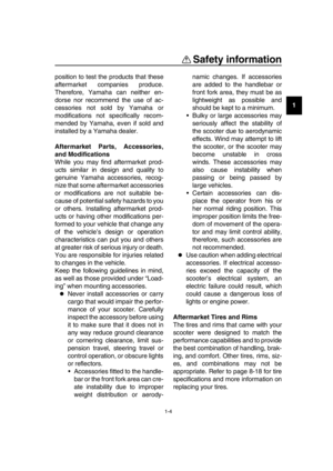 11
11 12
12 13
13 14
14 15
15 16
16 17
17 18
18 19
19 20
20 21
21 22
22 23
23 24
24 25
25 26
26 27
27 28
28 29
29 30
30 31
31 32
32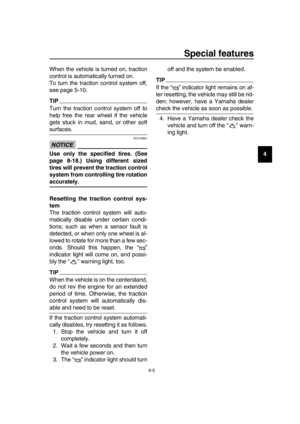 33
33 34
34 35
35 36
36 37
37 38
38 39
39 40
40 41
41 42
42 43
43 44
44 45
45 46
46 47
47 48
48 49
49 50
50 51
51 52
52 53
53 54
54 55
55 56
56 57
57 58
58 59
59 60
60 61
61 62
62 63
63 64
64 65
65 66
66 67
67 68
68 69
69 70
70 71
71 72
72 73
73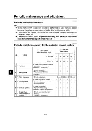 74
74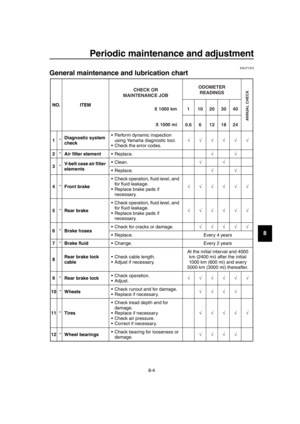 75
75 76
76 77
77 78
78 79
79 80
80 81
81 82
82 83
83 84
84 85
85 86
86 87
87 88
88 89
89 90
90 91
91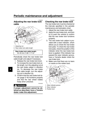 92
92 93
93 94
94 95
95 96
96 97
97 98
98 99
99 100
100 101
101 102
102 103
103 104
104 105
105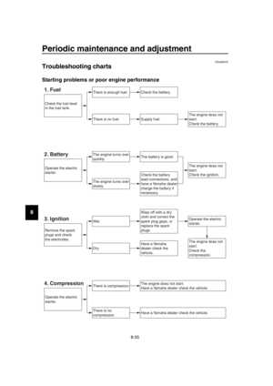 106
106 107
107 108
108 109
109 110
110 111
111 112
112 113
113 114
114 115
115 116
116 117
117 118
118 119
119 120
120 121
121