Page 97 of 122

Periodic maintenance and adjustment
8-26
1
2
3
4
5
6
7
8
9
10
11
12
13
14
EAU23215
Checking and l ubricating the
centerstand and sidestand
The operation of the centerstand and
sidestand should be checked before
each ride, and the pivots and metal-to-
metal contact surfaces should be lubri-
cated if necessary.
WARNING
EWA10742
If the centerstand or sidestand does
not move up and down smoothly,
have a Yamaha dealer check or re-
pair it. Otherwise, the centerstand or
sidestand could contact the ground
and distract the operator, resulting
in a possible loss of control.
EAU23273
Checking the front fork
The condition and operation of the front
fork must be checked as follows at the
intervals specified in the periodic main-
tenance and lubrication chart.
To check the condition
Check the inner tubes for scratches,
damage and excessive oil leakage.
To check the operation
1. Place the vehicle on a level sur- face and hold it in an upright posi-
tion. WARNING! To avoid injury,
securely support the vehicle so
there is no danger of it falling
over.
[EWA10752]
2. While applying the front brake, push down hard on the handlebars
several times to check if the front
fork compresses and rebounds
smoothly.
NOTICE
ECA10591
If any damage is found or the front
fork does not operate smoothly,
have a Yamaha dealer check or re-
pair it.Recommended lubricant:Lithium-soap-based grease
BV1-9-E2.book 26 ページ 2018年8月28日 火曜日 午後5時28分
Page 98 of 122
Periodic maintenance and adjustment
8-27
1
2
3
4
5
6
7
8
9
10
11
12
13
14
EAU45512
Checking the steering
Worn or loose steering bearings may
cause danger. Therefore, the operation
of the steering must be checked as fol-
lows at the intervals specified in the pe-
riodic maintenance and lubrication
chart. 1. Place the vehicle on the center- stand. WARNING! To avoid inju-
ry, securely support the vehicle
so there is no danger of it falling
over.
[EWA10752]
2. Hold the lower ends of the front fork legs and try to move them for-
ward and backward. If any free
play can be felt, have a Yamaha
dealer check or repair the steering.
EAU23292
Checking the wheel bearings
The front and rear wheel bearings must
be checked at the intervals specified in
the periodic maintenance and lubrica-
tion chart. If there is play in the wheel
hub or if the wheel does not turn
smoothly, have a Yamaha dealer check
the wheel bearings.
BV1-9-E2.book 27 ページ 2018年8月28日 火曜日 午後5時28分
Page 99 of 122

This model is equipped with a VRLA
(Valve Regulated Lea")
Periodic maintenance and adjustment
8-28
1
2
3
4
5
6
7
8
9
10
11
12
13
14
EAU77780
Battery
The battery is located under panel B.
(See page 8-7.)
This model is equipped with a VRLA
(Valve Regulated Lead Acid) battery.
There is no need to check the electro-
lyte or to add distilled water. However,
the battery lead connections need to be
checked and, if necessary, tightened.
WARNING
EWA10761
Electrolyte is poisonous and
dangerous since it contains sul-
furic acid, which causes severe
burns. Avoid any contact with
skin, eyes or clothing and al-
ways shield your eyes when
working near batteries. In case
of contact, administer the fol-
lowing FIRST AID. EXTERNAL: Flush with plenty of water.
INTERNAL: Drink large quan- tities of water or milk and im-
mediately call a physician.
EYES: Flush with water for 15 minutes and seek prompt
medical attention.
Batteries produce explosive hy- drogen gas. Therefore, keep
sparks, flames, cigarettes, etc.,
away from the battery and pro-
vide sufficient ventilation when
charging it in an enclosed
space.
KEEP THIS AND ALL BATTER-
IES OUT OF THE REACH OF
CHILDREN.
To charge the battery
Have a Yamaha dealer charge the bat-
tery as soon as possible if it seems to
have discharged. Keep in mind that the
battery tends to discharge more quickly
if the vehicle is equipped with optional
electrical accessories.
NOTICE
ECA16522
To charge a VRLA (Valve Regulated
Lead Acid) battery, a special (con-
stant-voltage) battery charger is re-
quired. Using a conventional battery
charger will damage the battery.
To store the battery 1. If the vehicle will not be used for more than one month, remove the
battery, fully charge it, and then
place it in a cool, dry place.
NOTICE: When removing the
battery, be sure turn the vehicle
power off, then disconnect the
negative lead before discon-
necting the positive lead.
[ECA21900]
2. If the battery will be stored for morethan two months, check it at least
once a month and fully charge it if
necessary.
3. Fully charge the battery before in- stallation. NOTICE: When install-
1. Negative battery lead (black)
2. Battery
3. Positive battery lead (red)
1
2 3
BV1-9-E2.book 28 ページ 2018年8月28日 火曜日 午後5時28分
Page 100 of 122
Periodic maintenance and adjustment
8-29
1
2
3
4
5
6
7
8
9
10
11
12
13
14 ing the battery, connect the
positive lead before connecting
the negative lead.
[ECA21910]
4. After installation, make sure that
the battery leads are properly con-
nected to the battery terminals.
NOTICE
ECA16531
Always keep the battery charged.
Storing a discharged battery can
cause permanent battery damage.
EAU81471
Replacing the fuses
The main fuse box and the fuse boxes,
which contain the fu ses for the individu-
al circuits, are located under panel A.
(See page 8-7.)
If a fuse is blown, replace it as follows. 1. Turn the vehicle power off.
2. Remove the blown fuse, and then install a new fuse of the specified
amperage. WARNING! Do not
use a fuse of a higher amperage
rating than recommended to
avoid causing extensive dam-
age to the electrical system and
possibly a fire.
[EWA15132]
1. Main fuse box cover
2. Main fuse
3. Spare main fuse
3
1
2
BV1-9-E2.book 29 ページ 2018年8月28日 火曜日 午後5時28分
Page 101 of 122
Periodic maintenance and adjustment
8-30
1
2
3
4
5
6
7
8
9
10
11
12
13
14
(XP530-A)
(XP530D-A)
(XP530D-A)
1. ABS control unit fuse
2. Auxiliary DC jack fuse
3. Headlight fuse
4. Spare fuse
5. ABS solenoid fuse
6. ABS motor fuse
7. Electronic throttle valve fuse
1. Spare fuse
2. Seat lock fuse
3. Signaling system fuse
4. Ignition fuse
5. Taillight fuse
6. Radiator fan motor fuse
7. Fuel injection system fuse
8. Backup fuse
4
765 123
1
34568
12
7
1. Spare fuse
2. Windshield motor fuse
3. Signaling system fuse
4. Ignition fuse
5. Taillight fuse
6. Radiator fan motor fuse
7. Fuel injection system fuse
8. Backup fuse
1. Brake light fuse
2. Cruise control fuse
3. Spare fuse
1
34568
12
7
3
1
2
BV1-9-E2.book 30 ページ 2018年8月28日 火曜日 午後5時28分
Page 102 of 122

Periodic maintenance and adjustment
8-31
1
2
3
4
5
6
7
8
9
10
11
12
13
14 3. Turn the vehicle power on and turn
on the electrical circuit in question
to check if the device operates.
4. If the fuse immediately blows again, have a Yamaha dealer
check the electrical system.
EAU77162
Vehicle lights
Except for the front turn signal lights
and license plate light, this model is
equipped with LED lighting. If a light
does not come on, check the fuses and
then have a Yamaha dealer check the
vehicle.
If a front turn signal light or license plate
light does not come, check and replace
the bulb.
NOTICE
ECA16581
Do not affix any type of tinted film or
stickers to the headlight lens.
Specified fuses:Main fuse:
40.0 A
Headlight fuse: 7.5 A
Taillight fuse: 7.5 A
Brake light fuse:
1.0 A (XP530D-A)
Signaling system fuse: 7.5 A
Ignition fuse: 7.5 A
Windshield motor fuse:
20.0 A (XP530D-A)
Radiator fan motor fuse: 15.0 A
Fuel injection system fuse: 7.5 A
ABS control unit fuse:
7.5 A
ABS motor fuse: 30.0 A
ABS solenoid fuse:
15.0 A
Cruise control fuse: 1.0 A (XP530D-A)
Backup fuse: 15.0 A
Electronic thrott le valve fuse:
7.5 A
Auxiliary DC jack fuse: 2.0 A
Seat lock fuse: 7.5 A (XP530-A)
1. Headlight
2. Auxiliary light
1
21
2
BV1-9-E2.book 31 ページ 2018年8月28日 火曜日 午後5時28分
Page 103 of 122
 by
tur")
Periodic maintenance and adjustment
8-32
1
2
3
4
5
6
7
8
9
10
11
12
13
14
EAU52323
Replacing a front turn signal
light bulb
1. Remove the turn signal light bulb socket (together with the bulb) by
turning it counterclockwise.
2. Remove the burnt-out bulb by pushing it in and turning it counter-
clockwise.
3. Insert a new bulb into the socket, push it in, and then turn it clock-
wise until it stops.
4. Install the socket (together with the bulb) by turning it clockwise.
EAU81491
Replacing the license plate
light bulb
1. Remove the nuts securing the li-cense plate light unit.
2. Pull the license plate light unit sep- arate from the rear fender. (Rein-
stall the collars if they fall out.)
3. Remove the burnt-out bulb by pull- ing it out.
4. Insert a new bulb into the socket, and push the socket in place.
5. Install the license plate unit onto the rear fender.
6. Install the nuts and tighten to the specified torque.
1. Turn signal light bulb socket
1. Turn signal light bulb
2. Turn signal light bulb socket
1
12
1. License plate light unit
2. Nut
1. License plate light unit
2. Collar
3. License plate light bulb
2 1
2
1
3
BV1-9-E2.book 32 ページ 2018年8月28日 火曜日 午後5時28分
Page 104 of 122

Periodic maintenance and adjustment
8-33
1
2
3
4
5
6
7
8
9
10
11
12
13
14
EAU25865
Troubleshooting
Although your Yamaha received a thor-
ough inspection before shipment from
the factory, trouble may occur during
operation. Any problem in the fuel,
compression, or ignition systems, for
example, can cause poor starting and
loss of power.
The following troubleshooting chart
represents a quick and easy procedure
for checking these vital systems your-
self. However, should your vehicle re-
quire any repair, take it to an authorized
Yamaha dealer whose skilled techni-
cians have the necessary tools, experi-
ence, and know-how to properly
service your Yamaha vehicle.
Be sure to use only genuine Yamaha
replacement parts. Although imitation
parts may look similar to genuine parts,
they are often inferior in quality, have a
shorter service life, and can lead to an
expensive repair bill later on.
WARNING
EWA15142
When checking the fuel system, do
not smoke, and make sure there are
no open flames or sparks in the ar-
ea, including pilot lights from water
heaters or furnaces. Gasoline or
gasoline vapors can ignite or ex-
plode, causing severe injury or
property damage.
EAU77992Smart key system troubleshooting
Please check the following items when
the smart key system does not work.
Is the smart key turned on? (See
page 3-5.)
Is the smart key battery dis-
charged? (See page 3-6.)
Tightening torque: License plate light unit nut:
3.8 N·m (0.38 kgf·m, 2.8 lb·ft)
BV1-9-E2.book 33 ページ 2018年8月28日 火曜日 午後5時28分
 1
1 2
2 3
3 4
4 5
5 6
6 7
7 8
8 9
9 10
10 11
11 12
12 13
13 14
14 15
15 16
16 17
17 18
18 19
19 20
20 21
21 22
22 23
23 24
24 25
25 26
26 27
27 28
28 29
29 30
30 31
31 32
32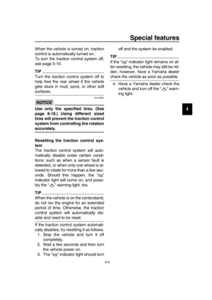 33
33 34
34 35
35 36
36 37
37 38
38 39
39 40
40 41
41 42
42 43
43 44
44 45
45 46
46 47
47 48
48 49
49 50
50 51
51 52
52 53
53 54
54 55
55 56
56 57
57 58
58 59
59 60
60 61
61 62
62 63
63 64
64 65
65 66
66 67
67 68
68 69
69 70
70 71
71 72
72 73
73 74
74 75
75 76
76 77
77 78
78 79
79 80
80 81
81 82
82 83
83 84
84 85
85 86
86 87
87 88
88 89
89 90
90 91
91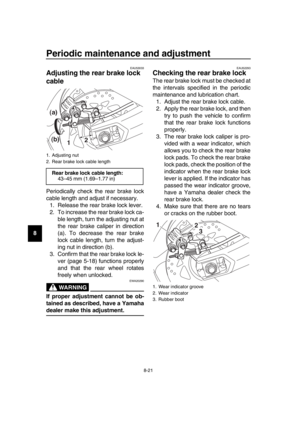 92
92 93
93 94
94 95
95 96
96 97
97 98
98 99
99 100
100 101
101 102
102 103
103 104
104 105
105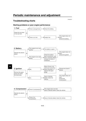 106
106 107
107 108
108 109
109 110
110 111
111 112
112 113
113 114
114 115
115 116
116 117
117 118
118 119
119 120
120 121
121
![YAMAHA TMAX 2019 Owners Manual Periodic maintenance and adjustment
8-29
1
2
3
4
5
6
7
8
9
10
11
12
13
14 ing the battery, connect the
positive lead before connecting
the negative lead.
[ECA21910]
4. After installation, make sure th](/manual-img/51/51454/w960_51454-99.png "YAMAHA TMAX 2019 Owners Manual Periodic maintenance and adjustment
8-29
1
2
3
4
5
6
7
8
9
10
11
12
13
14 ing the battery, connect the
positive lead before connecting
the negative lead.
[ECA21910]
4. After installation, make sure th")

(XP530D-A)
(XP530D-A)
1. ABS control unit fuse
2. Auxiliary DC jack fuse
3. Headlight fuse
4. Spare fuse
5. ABS sole")