2019 MERCEDES-BENZ GLC SUV battery
[x] Cancel search: batteryPage 172 of 673
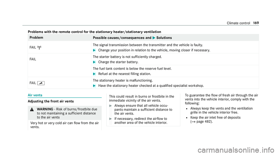
Problems with
there mo tecont rolfo r the stationary heater/stationary ventilation Problem
Possible causes/consequences and M
MSolutions
FA IL¨ The signal transmission between
the transmit ter and theve hicle is faulty. #
Chan geyour position in relation totheve hicle, moving closer if necessar y.
FA IL The
star ter battery is not suf ficiently charge d. #
Char gethest ar ter batter y.
The fuel tank content is below there ser vefuel le vel. #
Refuel at the nearest filling station.
FA IL¯ The
stationary heater is malfunctioning. #
Have thest ationary heater checked at a qualified specialist workshop. Air
vents Ad
justing the front air vents &
WARNING ‑ Risk of bu rns/frostbite due
to not maintaining a su fficient dis tance
to the air vents
Ve ry hot or very cold air can flow from the air
ve nts. This could
result in burns or frostbite in the
immediate vicinity of the air vents. #
Alw ays ensure that all vehicle occu‐
pants maintain a suf ficient di stance to
th e air vents. #
If necessa ry,re direct the air flow to
ano ther area of theve hicle interior. To
guarantee theflow of fresh air thro ugh the air
ve nts into theve hicle interior, comply with the
fo llowing:
R Alw ayske ep theve nts and theve ntilation
grille in theve hicle interior free.
R Keep the air inlet free of deposits
(/ page 482). Climate control
16 9
Page 175 of 673
R
theke y is located in theve hicle and thekey
battery is not dischar ged.
R or: a Digital Vehicle Key is located in the
mar ked space (/ page173).
R the brake pedal is not depressed. #
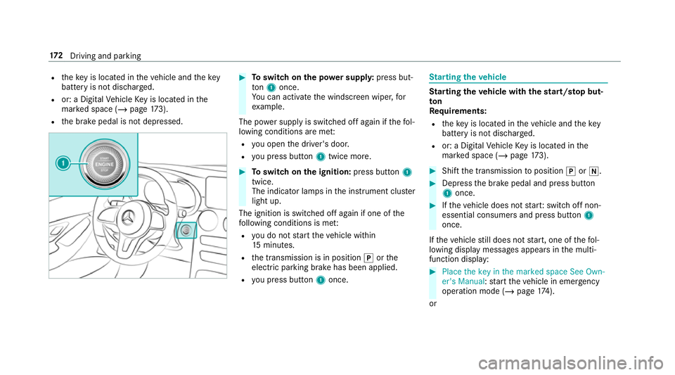
Toswitch on the po wer supp ly:press but‐
to n1 once.
Yo u can activate the windscreen wiper, for
ex ample.
The po wer supp lyis switched off again if thefo l‐
lowing conditions are me t:
R you open the driver's door.
R you press but ton1 twice more. #
Toswitch on the ignition: press button 1
twice.
The indicator lamps in the instrument clus ter
light up.
The ignition is switched off again if one of the
fo llowing conditions is me t:
R you do not start theve hicle within
15 minutes.
R the transmission is in position jorthe
electric parking brake has been applied.
R you press but ton1 once. St
arting theve hicle St
arting theve hicle with thest art/s top but‐
ton
Requ irements:
R theke y is located in theve hicle and thekey
battery is not dischar ged.
R or: a Digital Vehicle Key is located in the
mar ked space (/ page173). #
Shift the transmission toposition jori. #
Depress the brake pedal and press button
1 once. #
Ifth eve hicle does not star t:switch off non-
essential consumers and press button 1
once.
If th eve hicle still does not start, one of thefo l‐
lowing display messages appears in the multi‐
function display: #
Place the key in the marked space See Own-
er's Manual :st art theve hicle in emer gency
operation mode (/ page 174).
or 17 2
Driving and pa rking
Page 178 of 673
Ensu
rethefo llowing before starting the engine:
R the legal stipulations in the area where your
ve hicle is par ked allow engine starting via
smartphone.
R it is safe tostart and runth e engine where
yo ur vehicle is par ked.
R the fuel tank is su fficiently filled.
R thest ar ter battery is suf ficiently charge d.
% You can also set thete mp erature with your
smartphone. In form ation on Mercedes me
connect and other services: http://
www.mercedes.me
This function is not available for all models.
Charging the bat tery before commencing
yo ur journey
If th eve hicle battery is dischar ged, youre cei ve a
messa geon your smartphone. You can then
st art theve hicle with the smartphone tocharge
th e batter y.The vehicle is automatically
switched off af terte n minu tes. Ensure
thefo llowing before starting the engine:
R the legal stipulations in the area where your
ve hicle is par ked allow engine starting via
smartphone.
R it is safe tostart and runth e engine where
yo ur vehicle is par ked.
R the fuel tank is su fficiently filled.
St arting theve hicle (Remo teOnline) &
WARNING Risk of crushing or entrap‐
ment due tounin tentional starting of the
engine
Limbs could be crushed or trapped if the
engine is star ted unintentionally during
service or maintenance work. #
Alw ays secure the engine against unin‐
te ntional starting before car rying out
maintenance or repair work. Re
quirements:
R park position jis selected.
R the anti- theft alarm sy stem is not activated. R
the panic alarm is not activated.
R the hazard warning lights are switched off.
R the bonn etis closed.
R the doors are closed and loc ked.
R the windo wsand sliding sun roof are closed. #
Start theve hicle using the smartphone:
af te reve ryvehicle start, the engine runs for
te n minu tes.
yo u can car ryout a maximum of two consecu‐
tive starting attem pts. The vehicle must be star‐
te d once with theke y before trying tostart the
ve hicle again with the smartphone. you can stop
th eve hicle again at any time.
% further information can be found in the
smartphone app.
Securing the engine against starting before
car rying out maintenance or repair work: #
switch on the hazard warning lights.
or #
unlock the doors.
or Driving and parking
175
Page 210 of 673
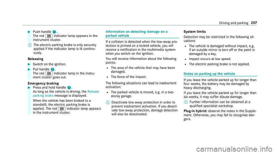
#
Push handle 1.
The red! indicator lamp appears in the
instrument clus ter.
% The electric parking brake is only securely
applied if the indicator lamp is lit continu‐
ously.
Re leasing #
Swit chon the ignition. #
Pull handle 1.
The red! indicator lamp in the instru‐
ment clus ter goes out.
Emer gency braking #
Press and hold handle 1.
As long as theve hicle is driving, theRelease
parking brake message is displa yed.
When theve hicle has been braked to a
st andstill, the electric parking brake is
applied. The red! indicator lamp appears
in the instrument clus ter. Information on de
tecting dama geon a
pa rked vehicle If a collision is de
tected when theto w- aw ay pro‐
te ction is primed on a loc kedve hicle, you will
re cei vea notification in the multimedia sy stem
when you swit chon the ignition.
Yo u will recei veinformation about thefo llowing
points:
R The area of theve hicle that may ha vebeen
damaged.
R The forc e of the impact.
The following situations can lead toinadver tent
acti vation:
R The pa rked vehicle is mo ved, e.g. in a two-
st or ey garage.
% Deactivate tow- aw ay protection in order to
pr eve nt inadver tent acti vation. If you deacti‐
va te tow- aw ay protection, damage de tection
will also be deactivated. Sy
stem limits
De tection may be restricted in thefo llowing sit‐
uations:
R The vehicle is damaged without impact, e.g.
if an outside mir ror is torn off or the paint is
damaged byakey.
R Impact occurs at low speed.
R The electric parking brake is not applied. Note
s on parking up theve hicle If
yo u lea vetheve hicle par ked up for longer than
fo ur we eks, the battery may be damaged by
heavy discharging.
If yo u lea vetheve hicle par ked up for longer than
six weeks, it may suf fer disuse dama ge.
% Further information can be obtained at a
qu alified specialist workshop.
Plug-in hybrid: obser vethe no tes in the Supple‐
ment. Otherwise, you may failto recognise dan‐
ge rs. Driving and pa
rking 207
Page 211 of 673
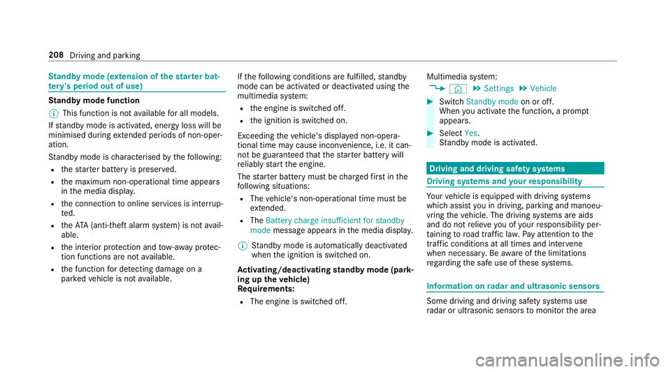
St
andby mode (extension of the star ter bat‐
te ry 's period out of use) St
andby mode function
% This function is not available for all models.
If standby mode is activated, ene rgy loss will be
minimised during extended pe riods of non-oper‐
ation.
St andby mode is characterised bythefo llowing:
R thest ar ter battery is preser ved.
R the maximum non-operational time appears
in the media displa y.
R the connection toonline services is inter rup‐
te d.
R theAT A (anti-theft alarm sy stem) is not avail‐
able.
R the interior pr otection and tow- aw ay protec‐
tion functions are not available.
R the function for de tecting damage on a
pa rked vehicle is not available. If
th efo llowing conditions are fulfilled, standby
mode can be activated or deactivated using the
multimedia sy stem:
R the engine is switched off.
R the ignition is switched on.
Exceeding theve hicle's displa yed non-opera‐
tional time may cause incon venience, i.e. it can‐
not be guaranteed that thest ar ter battery will
re liably start the engine.
The star ter battery must be charge dfirs t in the
fo llowing situations:
R The vehicle's non-operational time must be
ex tended.
R The Battery charge insufficient for standby
mode messa geappears in the media displa y.
% Standby mode is automatically deactivated
when the ignition is switched on.
Ac tivating/deactivating standby mode (park‐
ing up theve hicle)
Re quirements:
R The engine is switched off. Multimedia sy
stem:
4 © 5
Settings 5
Vehicle #
Switch Standby mode on or off.
When you activate the function, a prom pt
appears. #
Select Yes.
St andby mode is activated. Driving and driving saf
ety sy stems Driving sy
stems and your responsibility Yo
ur vehicle is equipped with driving sy stems
which assist you in driving, parking and manoeu‐
vring theve hicle. The driving sy stems are aids
and do not relie ve you of your responsibility per‐
ta ining toroad traf fic la w.Pay attention tothe
traf fic conditions at all times and inter vene
when necessa ry. Be aware of the limitations
re ga rding the safe use of these sy stems. Information on
radar and ultrasonic senso rs Some driving and driving sa
fety sy stems use
ra dar or ultrasonic sensors tomonitor the area 208
Driving and parking
Page 281 of 673
Tr
ailers with a 7-pin plug can be connec tedto
th eve hicle with thefo llowing adap ters:
R Adapter plug
R Adapter cable
The trailer will be cor rectly de tected bytheve hi‐
cle only if thefo llowing conditions are me t:
R The trailer is connected cor rectly
R The trailer lighting sy stem is in working order
The functions of thefo llowing sy stems are af fec‐
te dby a cor rectly connected traile r:
R Active Lane Keeping Assist
R ESP ®
trailer stabilisation
R Parking Assist PARKTRONIC
R Active Parking Assist
R Blind Spot Assist or Active Blind Spot Assi st
R Drive AwayAssi st
R Cross Traf fic Alert
R Trailer Manoeuv ring Assi st
R Reversing camera
R 360° camera Coupling up a trailer
* NO
TEDama getotheve hicle battery due
to full discharge Charging
the trailer battery using the po wer
supply of the trailer can damage theve hicle
batter y. #
Do not use theve hicle's po wer supply
to charge the trailer batter y. #
Remo vethe co ver from the ball head and
st ore it in a safe place (/ page116). #
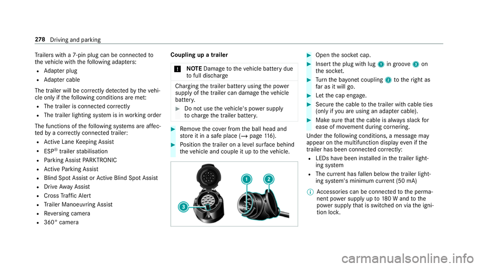
Position the trailer on a le vel sur face behind
th eve hicle and couple it up totheve hicle. #
Open the soc ket cap. #
Inse rtthe plug with lug 1in groo ve3 on
th e soc ket. #
Turn the ba yonet coupling 2totheright as
fa r as it will go. #
Let the cap engage. #
Secure the cable tothe trailer with cable ties
(only if you are using an adap ter cable). #
Make sure that the cable is alw ays slack for
ease of mo vement during cornering.
Under thefo llowing conditions, a message may
appear on the multifunction display even if the
trailer has been connected cor rectly:
R LEDs ha vebeen ins talled in the trailer light‐
ing sy stem
R The cur rent has fallen below the trailer light‐
ing sy stem's minimum cur rent (50 mA)
% Accessories can be connected tothe perma‐
nent po wer supp lyup to180 W and tothe
po we r supp lythat is swit ched on via the igni‐
tion loc k. 278
Driving and pa rking
Page 415 of 673
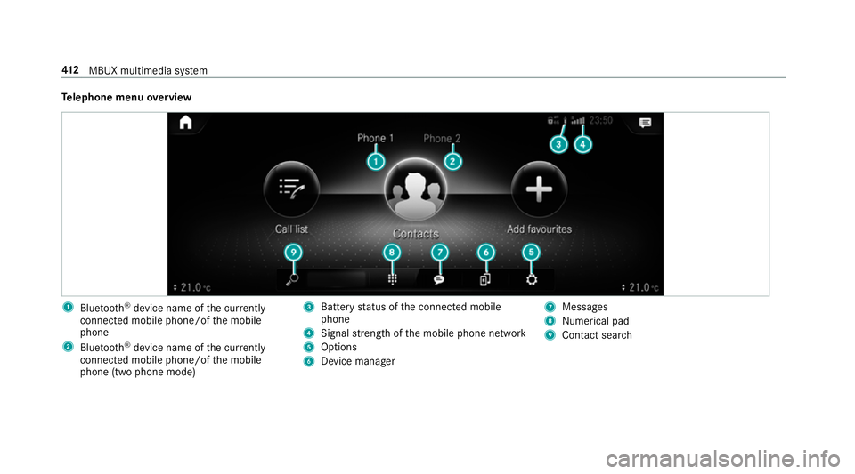
Te
lephone menu overview 1
Blue tooth ®
device name of the cur rently
connected mobile phone/of the mobile
phone
2 Blue tooth ®
device name of the cur rently
connected mobile phone/of the mobile
phone (two phone mode) 3
Battery status of the connected mobile
phone
4 Signal stre ngth of the mobile phone network
5 Options
6 Device manager 7
Messages
8 Nume rical pad
9 Contact sea rch 412
MBUX multimedia sy stem
Page 442 of 673
Overview of
the Mercedes-Benz emer gency
call sy stem
The Mercedes-Benz emer gency call sy stem can
help todecisively reduce the time between an
accident and the ar riva l of emer gency services
at the site of the accident. It helps locate an
accident site in places that are dif ficult to
access.
The emer gency call can be made au tomatical ly
( / page 439) or manually (/ page440). Only
make eme rgency calls if you or others are in
need of rescue. Do not make an emergency call
in theeve nt of a breakdown or a similar situa‐
tion.
Yo u can find more information on there gional
av ailability of the Mercedes-Benz emer gency call
sy stem at: http://www.mercedes-benz.com/
connect_ecall.
Message in the media displa y:
The following messages appear in the media dis‐
play:
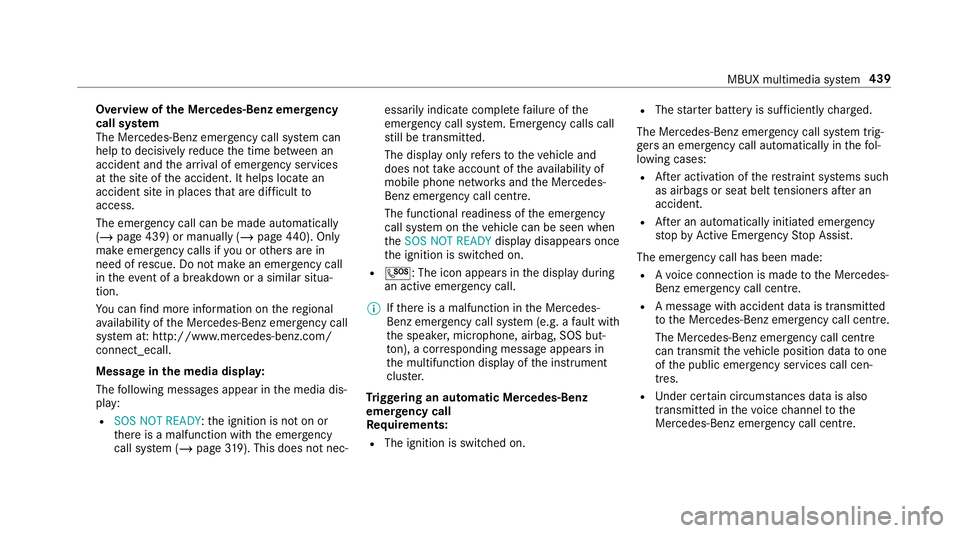
R SOS NOT READY :th e ignition is not on or
th ere is a malfunction with the emer gency
call sy stem (/ page319). This does not nec‐ essarily indica
tecompl etefa ilure of the
emer gency call sy stem. Emer gency calls call
st ill be transmitted.
The display only refers to theve hicle and
does not take account of theav ailability of
mobile phone networ ksand the Mercedes-
Benz emer gency call centre.
The functional readiness of the emer gency
call sy stem on theve hicle can be seen when
th eSOS NOT READY display disappears once
th e ignition is switched on.
R G: The icon appears in the display during
an active emer gency call.
% Ifth ere is a malfunction in the Mercedes-
Benz emer gency call sy stem (e.g. a fault with
th e speaker, microphone, airbag, SOS but‐
to n), a cor responding message appears in
th e multifunction display of the instrument
clus ter.
Tr iggering an automatic Mercedes-Benz
emer gency call
Re quirements:
R The ignition is switched on. R
The star ter battery is suf ficiently charge d.
The Mercedes-Benz emer gency call sy stem trig‐
ge rs an emer gency call au tomatical lyin thefo l‐
lowing cases:
R After activation of there stra int sy stems such
as airbags or seat belt tensioners af ter an
accident.
R After an auto maticallyinitiated emer gency
st op byActive Emergency Stop Assist.
The emer gency call has been made:
R Avo ice connection is made tothe Mercedes-
Benz emer gency call centre.
R A messa gewith accident data is transmitted
to the Mercedes-Benz emer gency call centre.
The Mercedes-Benz emergency call centre
can transmit theve hicle position data toone
of the public emer gency services call cen‐
tres.
R Under cer tain circums tances da tais also
transmitte d inthevo ice channel tothe
Mercedes-Benz emer gency call centre. MBUX multimedia sy
stem 439