2019 MERCEDES-BENZ GLC SUV inflation pressure
[x] Cancel search: inflation pressurePage 500 of 673
If a pressure loss
warning message appears in
th e multifunction displa y,proceed as follo ws:
R Check the tyre for dama ge.
R If driving on, obser vethefo llowing no tes.
Driving distance possible in emer gency
mode af ter the pressure loss warning: Load condition Driving distance pos‐
sible in emergency
mode
Pa rtially laden 80 km
Fu lly laden 30 kmThe driving dis
tance possible in emergency
mode may vary depending on the driving style.
Obser vethe maximum permissible speed of
80 km/h.
If a tyre has gone flat and cannot be replaced
with an MOEx tended tyre, you can use a stand‐
ard tyre as a temp orary measure. TIREFIT kit
storage location Plug-in
hybrid: be sure toobser vethe no tes in
th e Supplement. Otherwise, you may failto rec‐
ognise dangers.
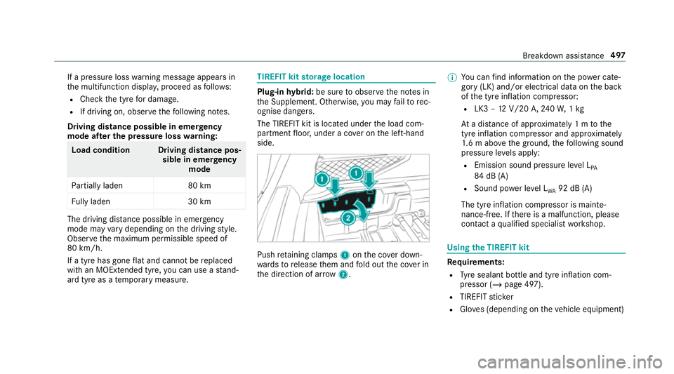
The TIREFIT kit is loca ted under the load com‐
partment floor, under a co ver on the left-hand
side. Push
retaining clamps 1onthe co ver down‐
wa rdsto release them and fold out the co ver in
th e direction of ar row2. %
You can find information on the po wer cate‐
gory (LK) and/or electrical data on the back
of the tyre inflation compressor:
R LK3 – 12V/20 A,240W, 1kg
At a dis tance of appr oximately 1 m tothe
tyre inflation compressor and appr oximately
1. 6 m abo vethe ground, thefo llowing sound
pressure le vels apply:
R Emission sound pressure le vel L
PA
84 dB (A)
R Sound po wer le vel L
WA 92 dB (A)
The tyre inflation compressor is mainte‐
nance-free. If there is a malfunction, please
conta ct aqualified specialist workshop. Using
the TIREFIT kit Re
quirements:
R Tyre sealant bottle and tyre inflation com‐
pressor (/ page 497).
R TIREFIT sticker
R Gloves (depending on theve hicle equipment) Breakdown assis
tance 497
Page 502 of 673
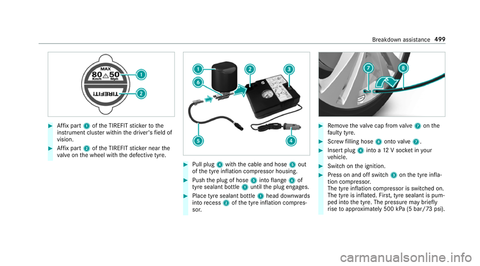
#
Affix pa rt1 ofthe TIREFIT sticke rto the
instrument clus ter within the driver's field of
vision. #
Affix pa rt2 ofthe TIREFIT sticke r near the
va lve on the wheel with the defective tyre. #
Pull plug 4with the cable and hose 5out
of the tyre inflation compressor housing. #
Push the plug of hose 5into flange 6of
tyre sealant bottle 1until the plug engages. #
Place tyre sealant bottle 1head down wards
into recess 2ofthe tyre inflation compres‐
sor. #
Remo vetheva lve cap from valve 7 onthe
fa ulty tyre. #
Screw filling hose 8onto valve 7. #
Insert plug 4into a 12V soc ket in your
ve hicle. #
Switch on the ignition. #
Press on and off switch 3onthe tyre infla‐
tion compressor.
The tyre inflation compressor is switched on.
The tyre is inflated. Fir st, tyre sealant is pum‐
ped into the tyre. The pressure may brief ly
ri se toappr oximately 500 kPa (5 bar/73 psi). Breakdown assis
tance 499
Page 503 of 673
Do not swit
choff the ty reinflation compres‐
sor during this phase! #
Let the tyre inflation compressor runfo r a
maximum of ten minu tes.
The tyre should then ha veattained a tyre
pressure of at least 200 kPa (2.0 bar/
29 psi).
If tyre sealant leaks out, make sure you clean the
af fected area as quickly as possible. It is prefera‐
ble touse clean water.
If yo uge t tyre sealant on your clo thing, ha veit
cleaned as soon as possible with per chloroe thy‐
lene.
If, af terte n minutes, a tyre pressure of
200 kPa (2.0 bar/29 psi) has not been
attained: #
Switch off the tyre inflation compressor. #
Unscr ew thefilling hose from theva lve of the
defective tyre.
Please no tethat tyre sealant may leak out when
unscr ewing thefilling hose. #
Drive forw ards or reve rseve ry slowly for
appr oximately 10m. #
Pump up the tyre again.
Af ter a maximum of ten minu testh e tyre
pressure must be at least 200 kPa (2.0 bar/
29 psi). &
WARNING Risk of accident due tothe
specified tyre pressure not being ach‐
ie ved
If th e specified tyre pressure is not achie ved
af te rth e specified time, the tyre is too badly
damaged. The tyre sealant cannot repair the
tyre in this ins tance.
Dama ged tyres and a tyre pressure that is
to o low can significantly impair braking and
handling characteristics. #
Do not drive on. #
Consult a qualified specialist workshop. If, af
terte n minutes, a tyre pressure of
200 kPa (2.0 bar/29 psi) has been attained: #
Switch off the tyre inflation compressor. #
Unscr ew thefilling hose from theva lve of the
defective tyre. &
WARNING Risk of accident from driving
wi th sealed tyres
A tyre temp orarily sealed with tyre sealant
impairs driving characteristics and is not
suitable for higher speeds. #
Adapt your driving style according lyand
drive carefull y. #
Do not exceed the maximum speed
limit with a tyre that has been repaired
using tyre sealant. #
Obser vethe maximum permissible speed for
a tyre sealed with tyre sealant 80 km/h. #
Affix th e upper section of the TIREFIT sticker
to the instrument clus ter in a location where
it will be easi lyseen bythe driver.
* NO
TEStaining from leaking tyre sealant Af
ter use, excess tyre sealant may leak out
from thefilling hose. 500
Breakdown assis tance
Page 504 of 673
#
Therefore, place thefilling hose in the
plastic bag that con tained the TIREFIT
kit. +
ENVIRONMEN
TALNO TEEnvironmental
pollution caused byenvironmen tally ir re‐
sponsible disposal Ty
re sealant contains polluta nts.#
Have the tyre sealant bottle disposed of
professionall y,e.g. at a Mercedes-Benz
Service Centre. #
Stow th e tyre sealant bottle, the tyre inflation
compressor and thewa rning triangle. #
Pull away immediatel y. #
Stop driving af ter appro ximately ten minu tes
and check the tyre pressure using the tyre
inflation compressor.
The tyre pressure must now be at least
13 0 kPa (1.3 bar/19 psi). &
WARNING Risk of accident due tothe
specified tyre pressure not being ach‐
ie ved
If th e specified tyre pressure is not achie ved
af te r a brief drive, the tyre is too badly dam‐
aged. The tyre sealant cannot repair the tyre
in this ins tance.
Dama ged tyres and a tyre pressure that is
to o low can significantly impair braking and
handling characteristics. #
Do not drive on. #
Consult a qualified specialist workshop. Countries
that ha veMercedes-Benz
Service24h: you will find a sticke r with thete le‐
phone number, e.g. on the B‑pillar on the driver's
side. #
Cor rect the tyre pressure if it is still at least
13 0 kPa (1.3 bar/19 psi). See the tyre pres‐
sure table on the fuel filler flap forva lues. #
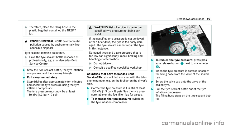
Toincrease the ty repressure: switch on
th e tyre inflation compressor. #
Toreduce the tyre pressure: press pres‐
su re re lease button 1next tomanome ter
2 . #
When the tyre pressure is cor rect, unscr ew
th efilling hose from theva lve of the sealed
tyre. #
Screw theva lve cap onto theva lve of the
sealed tyre. #
Pull the tyre sealant bottle out of the tyre
inflation compressor.
The filling hose stay s on the tyre sealant bot‐
tle. Breakdown assis
tance 501
Page 666 of 673
Tu
rn signal lights .....................................1 43
Switching on/off ................................. 14 3
TV ............................................................. 308
Ac tivating ............................................ 463
Ad justing the brightness ..................... 469
Calling up the menu (CI+ module) .......4 70
Information .......................................... 462
Overview ............................................. 464
Picture settings ................................... 469
Setting subtitles .................................. 468
Setting the audio language .................. 468
Showing telete xt .................................. 469
Showing/hiding full screen ................. 465
Te lete xt overview ................................. 468
Vo ice commands (LINGU ATRO NIC) .....3 08
TV channel
Ac tivating/deactivating channel fix ..... 466
Channel fix .......................................... 466
Channel li stove rview .......................... .467
Countr y-specific character set ............ 467
EPG (electronic programme guide) ...... 466
Overview of favo urites ........................ .467
Selecting from thech annel list ............ 465
Selecting from the control menu ......... 465
Selecting from thefa vo urites .............. 466 Selecting in
the bac kground ................ 466
St oring .................................................4 67
Tw o-w ayradios
Fr equencies ......................................... 538
No tes on ins tallation .......................... .537
Tr ansmission output (maximum) ........ .538
Ty re inflation compressor
see TIREFIT kit
Ty re pressure ........................................... 51 8
Checking (tyre pressure monitoring
sy stem) ................................................ 519
No tes ................................................... 517
Re starting the tyre pressure loss
wa rning sy stem ................................... 525
Re starting the tyre pressure monitor‐
ing sy stem ...........................................5 20
TIREFIT kit .......................................... .497
Ty re pressure loss warning sy stem
(function) ............................................. 525
Ty re pressure monitoring sy stem
(function) ............................................. 519
Ty re pressure table .............................. 51 8
Ty re pressure loss warning sy stem
Fu nction .............................................. 525 Re
starting ............................................ 525
Ty re pressure moni tor............................. 521
Ty re pressure moni toring sy stem
Checking the tyre pressure .................. 519
Checking the tyre temp erature ............ 519
Fu nction ............................................... 519
Re starting ............................................ 520
Ty re pressure table ................................. .518
Ty re temp erature
Checking (tyre pressure monitoring
sy stem) ................................................ 519
Ty re pressure monitoring sy stem
(function) ............................................. 519
Ty re tread ................................................. 516
Ty re-change tool kit
Overview ............................................ .529
Ty res
Changing hub caps .............................. 531
Checking .............................................. 516
Checking the tyre pressure (tyre
pressure monitoring sy stem) ............... 519
Fitting .................................................. 534
Flat tyre ............................................... 495 Index
663