2019 MERCEDES-BENZ EQC SUV battery
[x] Cancel search: batteryPage 161 of 629
Driving
Note
s on electric mode &
WARNING Risk ofchemical burns and
poisoning from damaged high-voltage
battery
If th e housing of the high-voltage battery has
been damaged, electrolyte and gases may
leak out. #
Avoid contact with the skin, eyes or
clo thing. #
Immediately rinse electrolyte splashes
off with water and seek medical atten‐
tion stra ight away. &
DANG ER Risk of explosion from exces‐
sive internal pressure of the high-voltage
battery
In theev ent of a vehicle fire ,th e internal
pressure of the high-voltage battery could
exc eed a critical value. In this case, flamma‐
ble gas escapes thro ugh a bleed valve in the
ve hicle's underbody. The
gas can ignite. #
Stop thech arging process immediately
in case of unusual odours, smo keor
burn mar ks. #
Lea vethe danger zone immediatel y.
Secu rethe danger zone at a suf ficient
di st ance. #
Call thefire service. Obser
vethefo llowing no tes on vehicle noise
emissions and the acoustic vehicle warning sys‐
te m:
R theve hicle is equipped with a purely electric
drive sy stem and de velops considerably
lo we rve hicle noise emissions than vehicles
with a combustion engine.
It is forth is reason that theve hicle is equip‐
ped with a sound generator, which ser ves as
an acoustic vehicle warning sy stem (A VAS).
R the sound generator generates speed-
dependent vehicle noise emissions when
driving forw ard and backing up at a speed of
up toaround 30 km/h. th
is helps other road users, particular ly
pede strians and bike riders, tohear your
ve hicle better.
R theve hicle acoustic warning sy stem gradu‐
ally switches off when driving at speeds
abo ve20 km/h.
R despite the sound generator, theve hicle still
may not be heard by otherroad users. Adapt
yo ur driving style accordingly.
R the sound generator is off when theve hicle
is stationar y. Manual disconnection of
the high-voltage on-
board electrical sy stem &
DANG ER Risk of fata l injury bytouching
damaged high-voltage co mponents
The vehicle's high-voltage on-board electrical
sy stem is under high voltage. If you modify
co mp onent parts in theve hicle's high-volt‐
age on-board electrical sy stem or touch dam‐
aged co mponent parts, you may be electro‐
cuted. 15 8
Driving and pa rking
Page 163 of 629
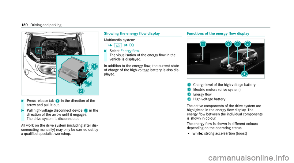
#
Press release tab1 inthe direction of the
ar row and pull it out. #
Pull high-voltage disconnect device 2inthe
direction of the ar row until it en gage s.
The drive sy stem is disconnected.
All workon the drive sy stem (including af ter dis‐
connecting manually) may only be car ried out by
a qu alified specialist workshop. Showing
the energy flow display Multimedia sy
stem:
4 © 5
EQ #
Select Energy flow.
The visualisation of the energy flow inthe
ve hicle is displa yed.
In addition tothe energy flow ,th e cur rent state
of charge ofthe high-voltage battery is also dis‐
pla yed. Fu
nctions of the energy flow displ ay 1
Char geleve l of the high-voltage battery
2 Elect ric mo tors (drive sy stem)
3 Energy flow
4 High-voltage battery
The active components of the drive sy stem are
highlighted in the energy flow displa y.The
energy flow between the individual components
is shown in colour.
The energy flow is shown in dif fere nt colou rs
depending on the operating status:
R white: strong acceleartion (boost) 16 0
Driving and pa rking
Page 164 of 629
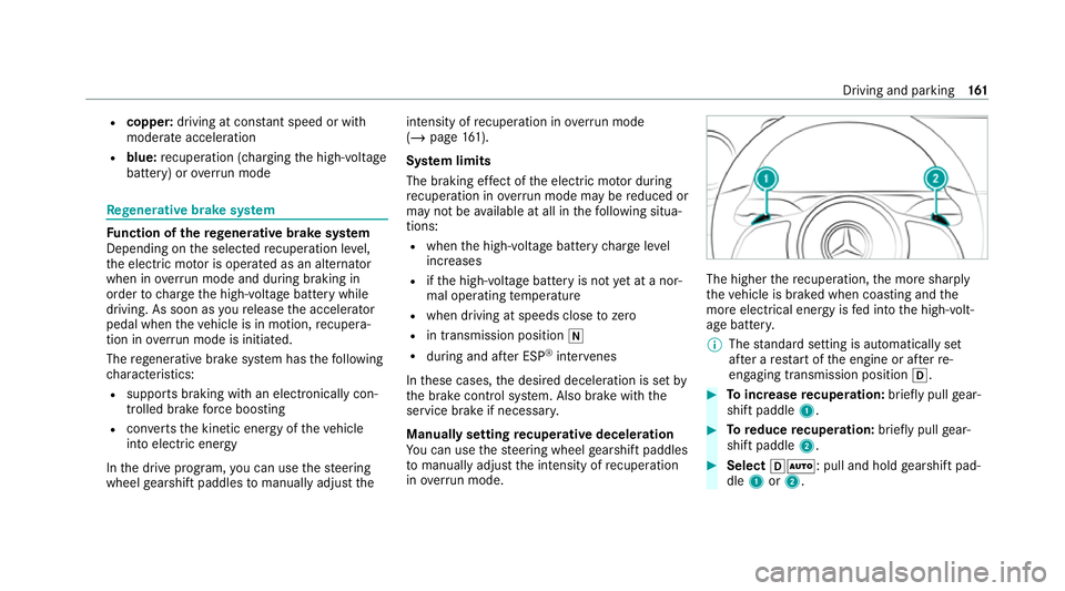
R
copper: driving at con stant speed or with
mode rate acceleration
R blue: recuperation (cha rging the high-voltage
battery) or overrun mode Re
generative brake sy stem Fu
nction of there ge nerative brake sy stem
Depending on the selected recuperation le vel,
th e electric mo tor is operated as an alternator
when in overru n mode and du ring braking in
order tocharge the high-voltage battery while
driving. As soon as youre lease the accelera tor
pedal when theve hicle is in motion, recupera‐
tion in overru n mode is initia ted.
The rege nerati vebrake sy stem has thefo llowing
ch aracteristics:
R suppo rts braking with an electronically con‐
trolled brake forc e boosting
R con verts th e kinetic energy of theve hicle
into electric energy
In the drive program, you can use thesteering
wheel gearshift paddles tomanually adju st theintensity of
recuperation in overru n mode
(/ page 161).
Sy stem limits
The braking ef fect of the electric mo tor during
re cuperation in overru n mode may be reduced or
may not be available at all in thefo llowing situa‐
tions:
R when the high-voltage battery charge level
inc reases
R ifth e high-voltage battery is not yet at a nor‐
mal operating temp erature
R when driving at speeds close tozero
R in transmission position i
R during and af ter ESP ®
inter venes
In these cases, the desired deceleration is set by
th e brake control sy stem. Also brake with the
service brake if necessar y.
Manually setting recuperative deceleration
Yo u can use thesteering wheel gearshift paddles
to manually adju stthe intensity of recuperation
in ove rrun mode. The higher
there cuperation, the more sharply
th eve hicle is braked when coasting and the
more electrical energy is fed into the high-volt‐
age batter y.
% The standard setting is automatically set
af te r a restart of the engine or af terre-
engaging transmission position h. #
Toincrease recuperation: briefly pull gear‐
shift paddle 1. #
Toreduce recuperation: briefly pull gear‐
shift paddle 2. #
Select hÃ: pull and hold gearshift pad‐
dle 1or2. Driving and parking
161
Page 165 of 629
The
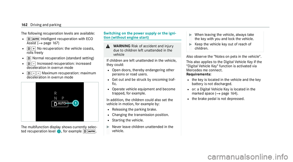
following recuperation le vels are available:
R hà Inte lligent recuperation wi thECO
Assi st (/ page 167)
R hq Norecuperation: theve hicle coasts,
ro lls freely
R h Normalrecuperation (s tanda rdsetting)
R h± Increased recuperation: increased
decele ration in overru n mode
R h±± Maximum recuperation: maximum
decele ration in overrun mode The multifunction displ
aysho wscurrently selec‐
te dre cuperation le vel1, forex ample hÃ. Swit
ching on the po wer supp lyor the igni‐
tion (without engine start) &
WARNING Risk of accident and inju ry
due tochildren left unat tended in the
ve hicle
If ch ildren are left unat tended in theve hicle,
th ey could:
R Open doo rs,th ereby endangering other
persons or road users.
R Get out and be stru ck byoncoming traf‐
fi c.
R Ope rate ve hicle equipment and become
trapped, forex ample.
In addition, thech ildren could also set the
ve hicle in motion, forex ample by:
R Releasing the parking brake.
R Changing the transmission position.
R Starting theve hicle. #
Never lea vechildren unat tended in the
ve hicle. #
When leaving theve hicle, alw aysta ke
th eke y with you and lock theve hicle. #
Keep theve hicle key out of reach of
ch ildren. Also obser
vethe "No tes on pets in theve hicle".
This also applies tothe Digital Vehicle Key if the
"Digital Vehicle Key" function is activated via
Mercedes me connect.
Re quirements:
R theke y is located in theve hicle and thekey
battery is not dischar ged.
R or: a Digital Vehicle Key is located in the
mar ked space (/ page164).
R the brake pedal is not depressed. 16 2
Driving and pa rking
Page 166 of 629
#
Toswitch on the po wer supp ly:press but‐
to n1 once.
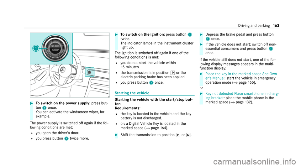
Yo u can activate the windscreen wiper, for
ex ample.
The po wer supp lyis switched off again if thefo l‐
lowing conditions are me t:
R you open the driver's door.
R you press but ton1 twice more. #
Toswitch on the ignition: press button 1
twice.
The indicator lamps in the instrument clus ter
light up.
The ignition is switched off again if one of the
fo llowing conditions is me t:
R you do not start theve hicle within
15 minutes.
R the transmission is in position jorthe
electric parking brake has been applied.
R you press but ton1 once. St
arting theve hicle St
arting theve hicle with thest art/s top but‐
ton
Requ irements:
R theke y is located in theve hicle and thekey
battery is not dischar ged.
R or: a Digital Vehicle Key is located in the
mar ked space (/ page164). #
Shift the transmission toposition jori. #
Depress the brake pedal and press button
1 once. #
Ifth eve hicle does not star t:switch off non-
essential consumers and press button 1
once.
If th eve hicle still does not start, one of thefo l‐
lowing display messages appears in the multi‐
function display: #
Place the key in the marked space See Own-
er's Manual :st art theve hicle in emer gency
operation mode (/ page 165).
or #
Key not detected Place smartphone in charg-
ing bracket: place the mobile phone in the
mar ked space (/ page132). Driving and pa
rking 16 3
Page 178 of 629
%
Tomanoeuvre with an open driver's door,
open the driver's door while stationary and
engage transmission position hork
again.
% Ifyo u ha veengaged park position jor
switched off the drive sy stem and no trans‐
mission position display is displa yed, secure
th eve hicle from rolling away ( /page 196).
Engaging drive position D #
Depress the brake pedal and push the
DIRECT SELECT le ver down past thefirst
point of resis tance.
The transmission position displ aysho wsh
in the multifunction displa y.Fu
nction of flexible all-wheel distribution
The flex ible all-wheel distribution means the
drive is alw ays ideally distributed between the
two axles. Depending on the situation, only the
front axle or only there ar axle can be driven, or
th e drive can be distributed continuously
between bo thaxles. This allo
ws the maximum recur rent delay tobe
achie ved (/ page161). The resulting recupera‐
tion increases theve hicle's range.
To get her with ESP ®
and 4ETS, theflex ible all-
wheel distribution impr ovesth e traction of your
ve hicle whene ver a driven wheel spins due to
insuf ficient traction.
If yo ufa ilto adapt your driving style, theflex ible
all-wheel distribution can neither reduce therisk
of accident nor override the la wsof ph ysics. It
cannot take into account road, weather or traf fic
conditions. The flex ible all-wheel distribution is
only an aid. You are responsible especially for
maintaining a safe dis tance from theve hicle in
front, forve hicle speed, for braking in good time
and forst ay ing in lane.
% In wint ryroad conditions, the maximum
ef fect of theflex ible all-wheel distribution
can be achie ved only if you use winter tyres
(M+S tyres), with sn ow chains if necessar y. Cha
rging the high-voltage bat tery Note
s oncharging the high-voltage bat tery *
NO
TEAccelerated ageing of the high-
vo ltage battery due tofrequent charging
to full Fr
equent charging tofull (charge le vel10 0%)
ch arging of the high-voltage batter y,espe‐
cially when this process is not direct lyfol‐
lo we dby a journe y,accelerates the ageing of
th e high-voltage batter y. #
Char gethe high-voltage battery on
ave rage toach arge leve l of 80%.
Be yond a charge leve l of 80%, the
ch arging time is considerably pro‐
lon ged. Driving and parking
175
Page 179 of 629
*
NO
TEDama gecaused tothe high-volt‐
age battery thro ugh lengt hyidle periods
or exhaustive discharging Lengt
hyidle periods with a high charge level
may result in an accelerated ageing of the
high-voltage batter y.
Exhaustive discha rging caused bythe battery
being idle for lengt hyperiods can damage
th e high-voltage batter y.#
Before long idle periods, pa rktheve hi‐
cle with a high-voltage battery charge
le ve l between 30% and 50%. Do not
ke ep the high-voltage battery continu‐
ously connected topowe r supp lyequip‐
ment. #
Check thech arge leve l of the high-volt‐
age battery every two tothre e months.
Re charge the high-voltage battery if the
ch arge leve l is insuf ficient. As a
result of its basic characteristics, the
amount of ene rgyav ailable from the high-voltage
battery decreases overth e course of its life. Due
tothis, the maximum range that can be ach‐
ie ve dby theve hicle is reduced and the maxi‐
mum output (acceleration) of theve hicle can be
re duced.
Yo u can cont ribute toreducing theve hicle's
energy consum ption in thefo llowing ways:
R An anticipatory driving style (/ page166)
R Reduced use of elect rical consumers
R Having theve hicle regularly maintained
The charging time of the high-voltage battery
may change overth e course of its life.
% You can check thech arge leve l of the high-
vo ltage battery in the multimedia sy stem
(/ page 160)
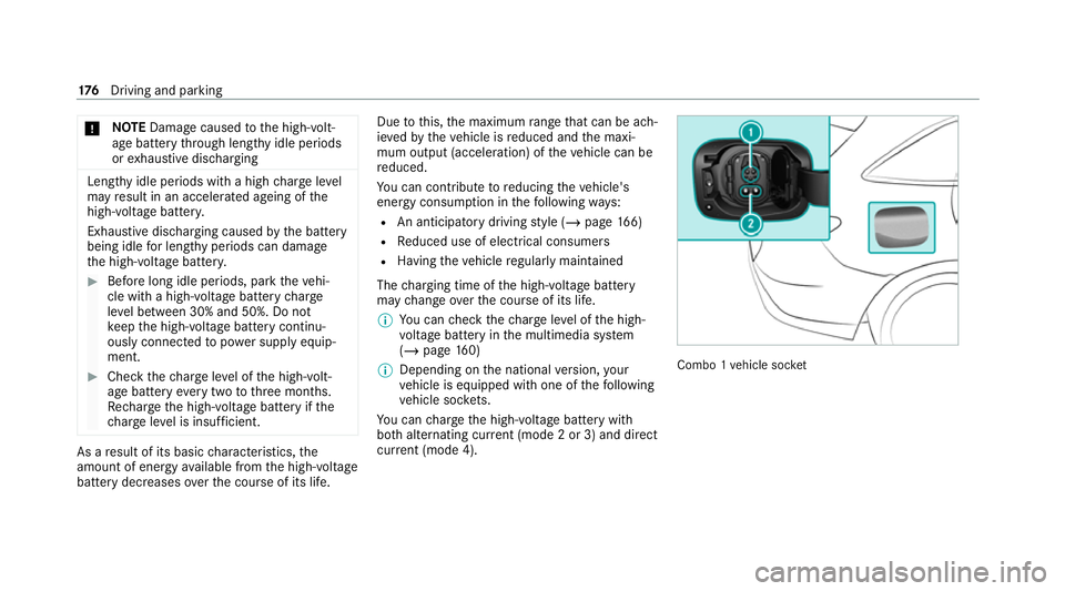
% Depending on the national version, your
ve hicle is equipped with one of thefo llowing
ve hicle soc kets.
Yo u can charge the high-voltage battery with
bo th alternating cur rent (mode 2 or 3) and di rect
cur rent (mode 4). Combo 1
vehicle soc ket 176
Driving and pa rking
Page 180 of 629
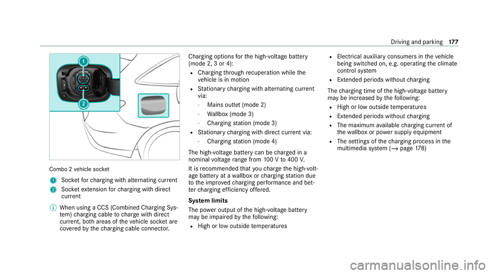
Combo 2
vehicle soc ket
1 Socketfo rch arging with alternating cur rent
2 Socketex tension forch arging with direct
cur rent
% When using a CCS (Combined Charging Sys‐
tem) charging cable tocharge with direct
cur rent, bo thareas of theve hicle soc ket are
co veredby thech arging cable connec tor. Charging options
forth e high-voltage battery
(mode 2, 3 or 4):
R Charging thro ugh recuperation while the
ve hicle is in motion
R Stationary charging with alternating cur rent
via:
- Mains outlet (mode 2)
- Wallbox (mode 3)
- Charging station (mode 3)
R Stationary charging with direct cur rent via:
- Charging station (mode 4)
The high-voltage bat tery can be charge d in a
nominal voltage range from 100 V to400 V.
It is recommended that youch arge the high-volt‐
age battery at a wallbox or charging station due
to the impr ovedch arging per form ance and bet‐
te rch arging ef ficiency of fere d.
Sy stem limits
The po wer output of the high-voltage battery
may be impaired bythefo llowing:
R High or low outside temp eratures R
Elect rical auxilia ryconsumers in theve hicle
being switched on, e.g. operating the climate
control sy stem
R Exte nded pe riods without charging
The charging time of the high-voltage battery
may be increased bythefo llowing:
R High or low outside temp eratures
R Exte nded pe riods without charging
R The maximum available charging cur rent of
th ewa llbox or po wer supply equipment
R The settings of thech arging process in the
multimedia sy stem (/ page178) Driving and pa
rking 17 7