2018 MERCEDES-BENZ G-CLASS warning light
[x] Cancel search: warning lightPage 144 of 294

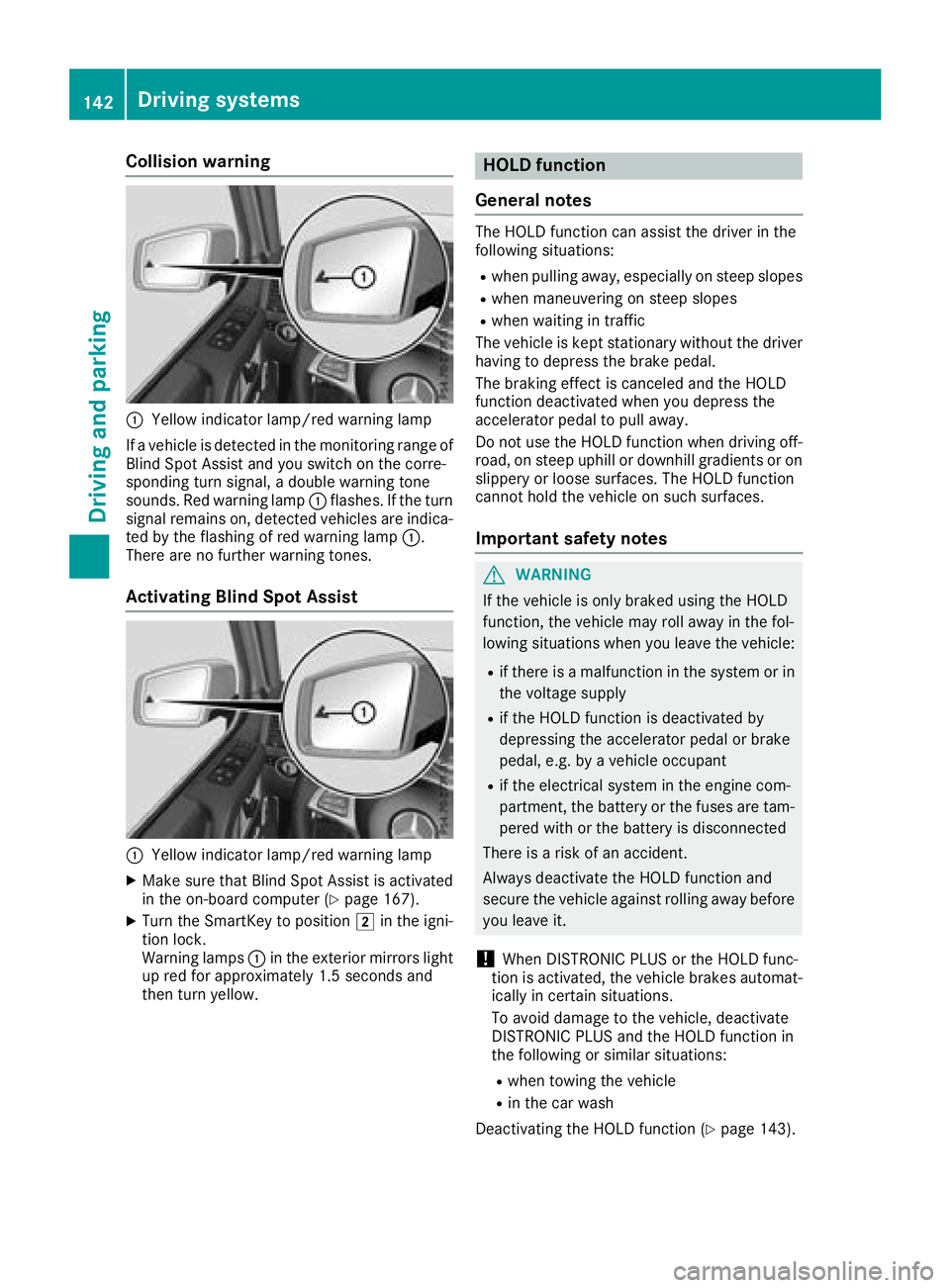
Collision warning
:Yellow indicator lamp/red warning lamp
If a vehicle is detected in the monitoring range of
Blind Spot Assist and you switch on the corre-
sponding turn signal, a double warning tone
sounds. Red warning lamp :flashes. If the turn
signal remains on, detected vehicles are indica-
ted by the flashing of red warning lamp :.
There are no further warning tones.
Activating Blind Spot Assist
:Yellow indicator lamp/red warning lamp
XMake sure that Blind Spot Assist is activated
in the on-board computer (Ypage 167).
XTurn the SmartKey to position 2in the igni-
tion lock.
Warning lamps :in the exterior mirrors light
up red for approximately 1.5 seconds and
then turn yellow.
HOLD function
General notes
The HOLD function can assist the driver in the
following situations:
Rwhen pulling away, especially on steep slopes
Rwhen maneuvering on steep slopes
Rwhen waiting in traffic
The vehicle is kept stationary without the driver having to depress the brake pedal.
The braking effect is canceled and the HOLD
function deactivated when you depress the
accelerator pedal to pull away.
Do not use the HOLD function when driving off-
road, on steep uphill or downhill gradients or on
slippery or loose surfaces. The HOLD function
cannot hold the vehicle on such surfaces.
Important safety notes
GWARNING
If the vehicle is only braked using the HOLD
function, the vehicle may roll away in the fol-
lowing situations when you leave the vehicle:
Rif there is a malfunction in the system or in the voltage supply
Rif the HOLD function is deactivated by
depressing the accelerator pedal or brake
pedal, e.g. by a vehicle occupant
Rif the electrical system in the engine com-
partment, the battery or the fuses are tam-
pered with or the battery is disconnected
There is a risk of an accident.
Always deactivate the HOLD function and
secure the vehicle against rolling away before
you leave it.
!When DISTRONIC PLUS or the HOLD func-
tion is activated, the vehicle brakes automat-
ically in certain situations.
To avoid damage to the vehicle, deactivate
DISTRONIC PLUS and the HOLD function in
the following or similar situations:
Rwhen towing the vehicle
Rin the car wash
Deactivating the HOLD function (
Ypage 143).
142Driving systems
Driving and parking
Page 146 of 294

the immediate vicinity of the vehicle. You
could damage the vehicle or the objects.
The sensors may not detect snow and other
objects that absorb ultrasonic waves.
Ultrasonic sources such as an automatic car
wash, the compressed-air brakes on a truck
or a pneumatic drill could cause PARKTRONIC
to malfunction.
PARKTRONIC may not function correctly on
uneven terrain.
PARKTRONIC is activated automatically when
you:
Rswitch on the ignition
Rshift the transmission to position h,kor
i
Rrelease the parking brake
PARKTRONIC is deactivated at speeds above
11 mph (18 km/h). It is reactivated at lower
speeds.
Range of the sensors
PARKTRONIC does not take objects into con-
sideration that are:
Rbelow the detection range, e.g. people, ani-
mals or objects.
Rabove the detection range, e.g. overhanging
loads, tail sections or loading ramps of goods
vehicles
:Example: sensors in the front bumper, right- hand side
:Approx. 24 in (approx. 60 cm) (corners)
;Approx. 32 in (approx. 80 cm) (corners)
=Approx. 35 in (approx. 90 cm) (center)
?Approx. 40 in (approx. 100 cm) (center)
The sensors must be free from dirt, ice or slush.
They can otherwise not function correctly. Clean
the sensors regularly, taking care not to scratch
or damage them (
Ypage 239).
Minimum distance
CenterApprox. 8 in (approx. 20 cm)
CornersApprox. 8 in (approx. 20 cm)
If there is an obstacle within this range, the rel-
evant warning displays light up and a warning
tone sounds. If the distance falls below the min-
imum, the distance may no longer be shown.
144Driving system s
Driving an d parking
Page 147 of 294

Warning displays
Warning display for the front area
:
Segments on the left-hand side of the vehi-
cle
;Segments on the right-hand side of the vehi-cle
=Segments showing operational readiness
The warning displays show the distance
between the sensors and the obstacle. The
warning display for the front area is located on
the dashboard above the center air vents. The
warning display for the rear area is located on
the headliner in the rear compartment.
The warning display for each side of the vehicle
is divided into five yellow and two red segments.
PARKTRONIC is operational if yellow segments
showing operational readiness =light up.
The selected transmission position and the
direction in which the vehicle is rolling deter-
mine which warning display is active when the
engine is running.
Transmission posi-
tionWarning display
hFront area activated
k, ior the vehicle
is rolling backwardsRear and front areas
activated
jNo areas activated
One or more segments light up as the vehicle
approaches an obstacle, depending on the vehi-
cle's distance from the obstacle.
From the:
Rsixth segment onwards, you will hear an inter-
mittent warning tone for approximately two
seconds.
Rseventh segment onwards, you will hear a
warning tone for approximately two seconds.
This indicates that you have now reached the minimum distance.
Deactivating/activating PARKTRONIC
:Indicator lamp
;Deactivates/activates PARKTRONIC
If indicator lamp :lights up, PARKTRONIC is
deactivated.
iPARKTRONIC is automatically activated
when you turn the SmartKey to position 2in
the ignition lock.
Towing a trailer
PARKTRONIC is deactivated for the rear area
when you establish an electrical connection
between your vehicle and a trailer.
Driving systems145
Driving and parking
Z
Page 148 of 294

Problems with PARKTRONIC
ProblemPossible causes/consequences andMSolutions
Only the red segments in
the PARKTRONIC warn-
ing displays are lit. You
also hear a warning tone
for approximately two
seconds.
PARKTRONIC is deacti-
vated after a few sec-
onds, and the indicator
lamp in the PARKTRONIC
button lights up.PARKTRONIC has malfunctioned and has switched off.
XIf problems persist, have PARKTRONIC checked at a qualified spe-
cialist workshop.
Only the red segments in
the PARKTRONIC warn-
ing displays are lit.
PARKTRONIC is deacti-
vated after a few sec-
onds.The PARKTRONIC sensors are dirty or there is interference.
XClean the PARKTRONIC sensors (Ypage 239).
XSwitch the ignition back on.
The problem may be caused by an external source of radio or ultra-
sound waves.
XSee if PARKTRONIC functions in a different location.
Rear view camera
General notes
Rear view camera :is an optical parking and
maneuvering aid. It shows the area behind the
vehicle with guide lines in the multimedia sys-
tem.
The area behind the vehicle is displayed as a
mirror image, as in the rear view mirror.
iThe text shown in the multimedia system
depends on the language setting. The follow-
ing are examples of rear view camera displays
in the multimedia system.
Important safety notes
The rear view camera is only an aid. It is not a
replacement for your attention to your immedi-
ate surroundings. You are always responsible
for safe maneuvering and parking. Make sure
that there are no persons, animals or objects in
the maneuvering area while maneuvering and
parking in parking spaces.
Under the following circumstances, the rear
view camera will not function, or will function in
a limited manner:
Rthe rear door is open
Rin heavy rain, snow or fog
Rat night or in very dark places
Rif the camera is exposed to very bright light
Rif the area is lit by fluorescent bulbs or LED
lighting (the display may flicker)
Rif there is a sudden change in temperature,
e.g. when driving into a heated garage in win- ter
Rif the camera lens is dirty or obstructed.
Observe the notes on cleaning
(
Ypage 240)
Rif the rear of your vehicle is damaged. In this
case, have the camera position and setting
checked at a qualified specialist workshop
146Driving systems
Driving and parking
Page 150 of 294

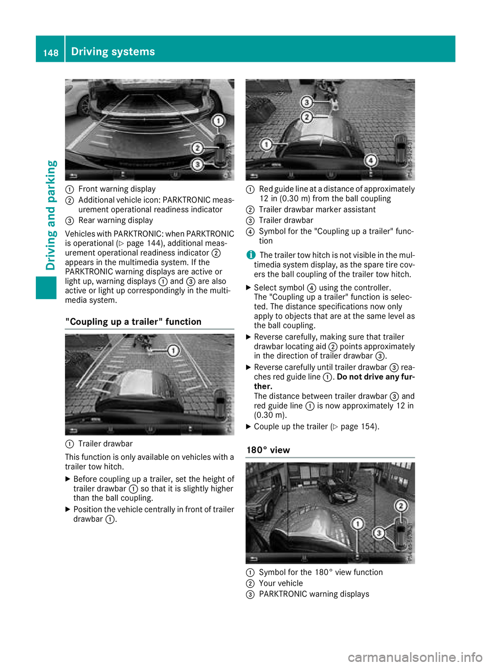
:Front warning display
;Additional vehicle icon: PARKTRONIC meas-
urement operational readiness indicator
=Rear warning display
Vehicles with PARKTRONIC: when PARKTRONIC
is operational (
Ypage 144), additional meas-
urement operational readiness indicator ;
appears in the multimedia system. If the
PARKTRONIC warning displays are active or
light up, warning displays :and =are also
active or light up correspondingly in the multi-
media system.
"Coupling up a trailer" function
:Trailer drawbar
This function is only available on vehicles with a
trailer tow hitch.
XBefore coupling up a trailer, set the height of
trailer drawbar :so that it is slightly higher
than the ball coupling.
XPosition the vehicle centrally in front of trailer
drawbar :.
:Red guide line at a distance of approximately
12 in (0.30 m) fromthe ball coupling
;Trailer drawbar marker assistant
=Trailer drawbar
?Symbol for the "Coupling up a trailer" func-
tion
iThe trailer tow hitch is not visible in the mul-
timedia system display, as the spare tire cov-
ers the ball coupling of the trailer tow hitch.
XSelect symbol ?using the controller.
The "Coupling up a trailer" function is selec-
ted. The distance specifications now only
apply to objects that are at the same level as
the ball coupling.
XReverse carefully, making sure that trailer
drawbar locating aid ;points approximately
in the direction of trailer drawbar =.
XReverse carefully until trailer drawbar =rea-
ches red guide line :.Do not drive any fur-
ther.
The distance between trailer drawbar =and
red guide line :is now approximately 12 in
(0.30 m).
XCoupleup the trailer (Ypage 154).
180° view
:Symbol for the 180° view function
;Your vehicle
=PARKTRONIC warning displays
148Driving system s
Driving an d parking
Page 151 of 294

You can also use the rear view camera to select
a 180° view.
When PARKTRONIC is operational (
Ypage 144),
a symbol for your own vehicle appears in the
multimedia system. If the PARKTRONIC warning
displays are active, warning displays =light up
in the multimedia system in yellow or red
accordingly.
Off-road driving systems
Transfer case
General notes
The vehicle has permanent all-wheel drive. The
front and rear axles are constantly driven.
For further information on driving off-road, see
(
Ypage 129).
Shift ranges
HIGH
RANGEPosition for all normal on-
road driving conditions
LOW RANGEOff-road gear for driving off-
road.
Also for use on steep uphill or
downhill gradients, especially
when towing a trailer.
The vehicle travels around
half the speed of on-road driv-
ing range HIGH RANGE. The
tractive power is correspond-
ingly higher.
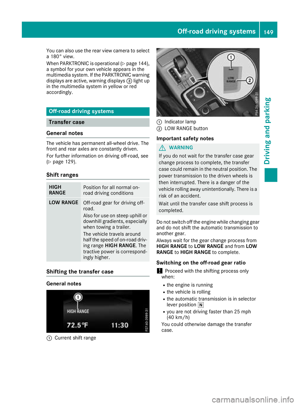
Shifting the transfer case
General notes
:Current shift range
:Indicator lamp
;LOW RANGE button
Important safety notes
GWARNING
If you do not wait for the transfer case gear
change process to complete, the transfer
case could remain in the neutral position. The power transmission to the driven wheels is
then interrupted. There is a danger of the
vehicle rolling away unintentionally. There is a
risk of an accident.
Wait until the transfer case shift process is
completed.
Do not switch off the engine while changing gear
and do not shift the automatic transmission to
another gear.
Always wait for the gear change process from
HIGH RANGE toLOW RANGE and fromLOW
RANGE toHIGH RANGE to complete.
Switching on the off-road gear ratio
!Proceed with the shifting process only
when:
Rthe engine is running
Rthe vehicle is rolling
Rthe automatic transmission is in selector
lever position i
Ryou are not driving faster than 25 mph
(40 km/h)
You could otherwise damage the transfer
case.
Off-road driving systems149
Driving and parking
Z
Page 152 of 294

XMake sure the ECO start/stop function is
switched off (Ypage 108).
XPress LOW RANGE button;.
Once the shifting procedure has been com-
pleted, the LOW RANGE
transfer case position
is shown in the multifunction display.
Indicator lamp :lights up.
XShift the automatic transmission to position
h.
Switching off the off-road gear ratio
GWARNING
If you do not wait for the transfer case gear
change process to complete, the transfer
case could remain in the neutral position. The power transmission to the driven wheels is
then interrupted. There is a danger of the
vehicle rolling away unintentionally. There is a
risk of an accident.
Wait until the transfer case shift process is
completed.
!Proceed with the shifting process only
when:
Rthe engine is running
Rthe vehicle is rolling
Rthe automatic transmission is in selector
lever position i
Ryou are not driving faster than 43 mph
(70 km/h)
You could otherwise damage the transfer
case.
XPress button ;.
Once the shifting procedure has been com-
pleted, the HIGH
RANGEtransfer case position
is shown in the multifunction display.
Indicator lamp :goes out.
If the shifting procedure is unsuccessful, the
multifunction display may show the following
messages:
RTC Shift Conditions Not Fulfilled
You have not met one or more shift condi-
tions.
RTC NEUTRAL On
The transfer case has canceled the shifting
procedure and is in Neutral.
RTC Shift Canceled
The transfer case has canceled the gear
change process.
XCarry out the gear change process again.
Make sure to meet all conditions for changing
gears.
RTC Malfunction Visit Workshop
There is a malfunction in the transfer case.
XDo not shift the transfer case.
XHave the vehicle checked as soon as possible
at a qualified specialist workshop.
Shifting to neutral
GWARNING
If you do not wait for the transfer case gear
change process to complete, the transfer
case could remain in the neutral position. The power transmission to the driven wheels is
then interrupted. There is a danger of the
vehicle rolling away unintentionally. There is a
risk of an accident.
Wait until the transfer case shift process is
completed.
XTurn the SmartKey to position 2in the igni-
tion lock.
XApply the parking brake.
XDepress the brake pedal.
XShift the automatic transmission to position
i.
XPress and hold LOW RANGE button ;for
approximately ten seconds.
When the shift procedure is complete, the
multifunction display shows the TC
NEUTRALOnmessage for five seconds.
If the shifting procedure is unsuccessful, the
multifunction display may show the following
messages (
Ypage 183).
If the transfer case is in Neutral, the SmartKey
is in the ignition lock and you open the driver's
door, the TC NEUTRAL On
message appears in
the multifunction display. If you then release the
parking brake, a warning tone will sound.
150Off-road driving systems
Driving and parking
Page 154 of 294

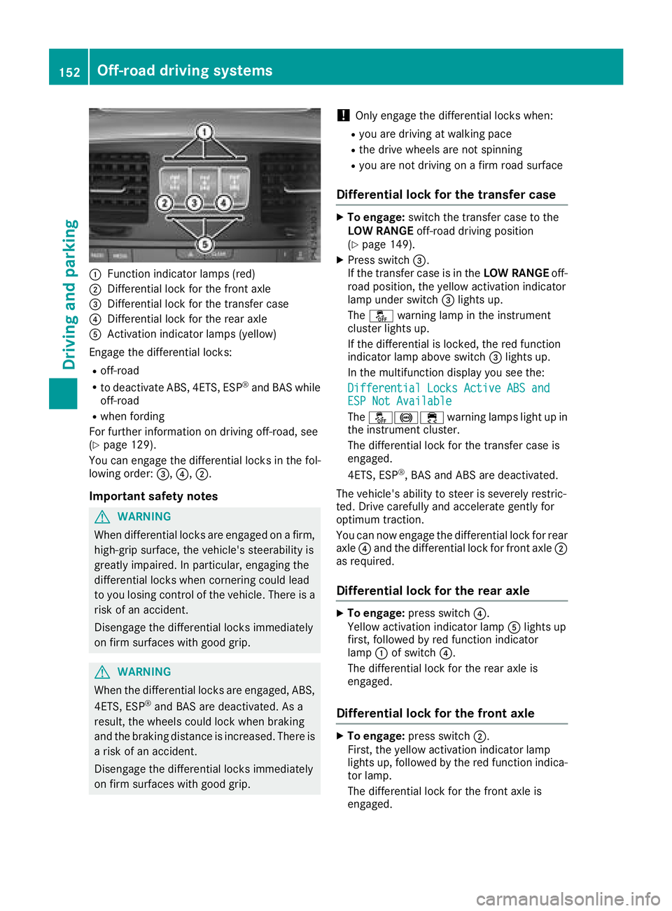
:Function indicator lamps (red)
;Differential lock for the front axle
=Differential lock for the transfer case
?Differential lock for the rear axle
AActivation indicator lamps (yellow)
Engage the differential locks:
Roff-road
Rto deactivate ABS, 4ETS, ESP®and BAS while
off-road
Rwhen fording
For further information on driving off-road, see
(
Ypage 129).
You can engage the differential locks in the fol-
lowing order: =,?,;.
Important safety notes
GWARNING
When differential locks are engaged on a firm,
high-grip surface, the vehicle's steerability is
greatly impaired. In particular, engaging the
differential locks when cornering could lead
to you losing control of the vehicle. There is a risk of an accident.
Disengage the differential locks immediately
on firm surfaces with good grip.
GWARNING
When the differential locks are engaged, ABS, 4ETS, ESP
®and BAS are deactivated. As a
result, the wheels could lock when braking
and the braking distance is increased. There is
a risk of an accident.
Disengage the differential locks immediately
on firm surfaces with good grip.
!Only engage the differential locks when:
Ryou are driving at walking pace
Rthe drive wheels are not spinning
Ryou are not driving on a firm road surface
Differential lock for the transfer case
XTo engage: switch the transfer case to the
LOW RANGE off-road driving position
(
Ypage 149).
XPress switch =.
If the transfer case is in the LOW RANGEoff-
road position, the yellow activation indicator
lamp under switch =lights up.
The å warning lamp in the instrument
cluster lights up.
If the differential is locked, the red function
indicator lamp above switch =lights up.
In the multifunction display you see the:
Differential Locks Active ABS and
ESP Not Available
The å!÷ warning lamps light up in
the instrument cluster.
The differential lock for the transfer case is
engaged.
4ETS, ESP
®, BAS and ABS are deactivated.
The vehicle's ability to steer is severely restric-
ted. Drive carefully and accelerate gently for
optimum traction.
You can now engage the differential lock for rear
axle ?and the differential lock for front axle ;
as required.
Differential lock for the rear axle
XTo engage: press switch ?.
Yellow activation indicator lamp Alights up
first, followed by red function indicator
lamp :of switch ?.
The differential lock for the rear axle is
engaged.
Differential lock for the front axle
XTo engage: press switch ;.
First, the yellow activation indicator lamp
lights up, followed by the red function indica-
tor lamp.
The differential lock for the front axle is
engaged.
152Off-road driving systems
Driving and parking