2018 MERCEDES-BENZ G-CLASS load capacity
[x] Cancel search: load capacityPage 11 of 294

Fuel ................................................ 124
General .......................................... 124
Gravel roads .................................. 131
Hydroplaning .................................127
Icy road surfaces ........................... 128
Important safety notes .................. 104
Limited braking efficiency on sal-
ted roads ....................................... 126
Off-road driving .............................. 129
Off-road fording .............................1 28
Pulling away on slippery surfaces .. 127
Snow chains .................................. 259
Subjecting brakes to a load ........... 126
The first 1500 km .......................... 104
Tire ruts ......................................... 131
Towing a trailer .............................. 154
Traveling uphill ............................... 132
Wet road surface ........................... 126
DVD audio
Operating (on-board computer) ..... 165
DVD video
Operating (on-board computer) ..... 166
see also Digital Operator's Man-
ual ..................................................2 03
E
EASY-ENTRY feature
Activating/deactivating ................. 170
Function/notes ................................ 81
EASY-EXIT feature
Function/notes ................................ 81
Switching on/off ........................... 170
EBD (electronic brake force distri-
bution)
Display message ............................ 176
Function/notes ................................ 61
ECO start/stop function
Deactivating/activating ................. 108
General information ....................... 107
Electronic Stability Program
see ESP
®(Electronic Stability Program)
Electronic Traction System
see 4ETS (Electronic Traction System)
Emergency
Automatic measures after an acci-
dent ................................................. 50 Emergency release
Driver's door ....................................6 8
Vehicle .............................................6 8
Emergency Tensioning Devices
Activation ........................................ .47
Emissions control
Service and warranty information .... 24
Engine
Check Engine warning lamp .......... .199
Display message ............................ 180
ECO start/stop function ................ 107
Engine number ............................... 283
Irregular running ............................ 110
Jump-starting ................................. 249
Starting problems .......................... 110
Starting the engine with the
SmartKey ....................................... 106
Switching off .................................. 123
Tow-starting (vehicle) ..................... 254
Engine electronics
Problem (malfunction) ................... 110
Engine oil
Adding ...........................................2 33
Additives ........................................ 286
Checking the oil level ..................... 232
Checking the oil level using the
dipstick .......................................... 232
Checking the oil level using the
on-board computer ........................ 232
Display message ............................ 182
Filling capacity ....... ........................ 286
G
eneral notes ................................ 285
Notes about oil grades ................... 285
Notes on oil level/consumption .... 232
Temperature (on-board com-
puter) ............................................. 171
Entering an address
see also Digital Operator's Man-
ual ..................................................2 03
ESP
®(Electronic Stability Pro-
gram)
4ETS (Electronic Traction Sys-
tem) ................................................. 59
AMG menu (on-board computer) ... 171
Characteristics ................................. 60
Deactivating/activating ................... 60
Display message ............................ 175
Function/notes ................................ 59
Index9
Page 21 of 294

Maximum tire load .........................272
Maximum tire load (definition) ....... 274
Optional equipment weight (defi-
nition) ............................................ 275
PSI (pounds per square inch) (def-
inition) ...........................................2 75
Replacing ....................................... 275
Service life ..................................... 258
Sidewall (definition) ....................... 275
Snow chains .................................. 259
Speed rating (definition) ................ 274
Storing ...........................................2 76
Structure and characteristics
(definition) ..................................... 273
Summer tires in winter .................. 259
Temperature .................................. 269
TIN (Tire Identification Number)
(definition) ..................................... 275
Tire bead (definition) ......................2 75
Tire pressure (definition) ................ 275
Tire pressures (recommended) ...... 274
Tire size (data) ............................... 279
Tire size designation, load-bearing
capacity, speed rating .................... 270
Tire tread ....................................... 258
Tire tread (definition) ..................... 275
Total load limit (definition) ............. 275
Traction ......................................... 269
Traction (definition) ....................... 275
Tread wear ..................................... 269
TWR (permissible trailer drawbar
noseweight) (definition) ................. 275
Uniform Tire Quality Grading
Standards ...................................... 269
Uniform Tire Quality Grading
Standards (definition) .................... 273
Wear indicator (definition) ............. 275
Wheel and tire combination ........... 279
Wheel rim (definition) .................... 274
see Flat tire
Top Tether ............................................ 52
Tow-starting
Emergency engine starting ............ 254
Important safety notes .................. 251
Towing a trailer
Axle load, permi
ssible .................... 291
Cleaning the trailer tow hitch ......... 240
Coupling up a trailer ...................... 157 Decoupling a trailer ....................... 158
Driving tips .................................... 154
ESP
®(Electronic Stability Pro-
gram) ............................................... 61
Important safety notes .................. 153
Installing the ball coupling ............. 156
Lights display message .................. 180
Pulling away with a trailer .............. 107
Shift range ..................................... 115
Trailer loads ................................... 291
Trailer tow hitch ............................. 291
Towing away
Important safety guidelines ........... 251
In the event of malfunctions .......... 253
With both axles on the ground ....... 252
Towing eye
Front .............................................. 252
Rear ............................................... 252
Traffic reports
see also Digital Operator's Man-
ual .................................................. 203
Trailer
7-pin connector ............................. 159
Power supply ................................. 159
Trailer coupling
see Towing a trailer
Trailer loads
Technical data ............................... 291
Trailer loads and drawbar nose-
weights ............................................... 159
Trailer tow hitch
Ball position ................................... 291
Trailer towing
PARKTRONIC ................................. 145
Permissible trailer loads and
drawbar noseweights ..................... 159
Transfer case
General notes ................................ 149
Shift range ..................................... 149
Shifting .......................................... 149
Shifting (general notes) .................. 149
Shifting (important safety notes) ... 149
Shifting to neutral .......................... 150
Switching off the off-road gear
ratio ............................................... 150
Switching on the off-road gear
ratio ............................................... 149
Index19
Page 214 of 294
level of protection and could even cause
injuries.
RObjects or loads in the trunk/cargo com-
partment cannot be restrained by the seat
backrest.
There is an increased risk of injury.
Before every trip, make sure that the seat
backrests and the rear bench seat/rear seat
are engaged.
GWARNING
Combustion engines emit poisonous exhaust
gases such as carbon monoxide. If the rear
door is open when the engine is running, par-
ticularly if the vehicle is moving, exhaust
fumes could enter the passenger compart-
ment. There is a risk of poisoning.
Turn off the engine before opening the rear
door. Never drive with the rear door open.
!Ensure that you remove all containers from
the cup holder in the rear before folding the
seat backrest and the seat cushion of the rear
bench seat forwards.
Observe the loading guidelines (
Ypage 209).
The rear bench seat is split symmetrically.
The left-hand and right-hand rear bench seats
can be folded forward to increase the capacity
of the rear compartment. You can:
Rfold the seat backrests forward
Rfold the rear bench seat back fully
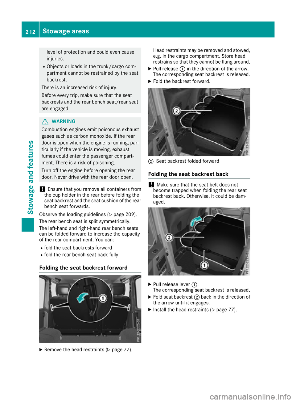
Folding the seat backrest forward
XRemove the head restraints (Ypage 77). Head restraints may be removed and stowed,
e.g. in the cargo compartment. Store head
restrains so that they cannot be flung around.
XPull release
:in the direction of the arrow.
The corresponding seat backrest is released.
XFold the backrest forward.
;Seat backrest folded forward
Folding the seat backrest back
!Make sure that the seat belt does not
become trapped when folding the rear seat
backrest back. Otherwise, it could be dam-
aged.
XPull release lever :.
The corresponding seat backrest is released.
XFold seat backrest ;back in the direction of
the arrow until it engages.
XInstall the head restraints (Ypage 77).
212Stowage areas
Stowage and features
Page 269 of 294
Number of seats
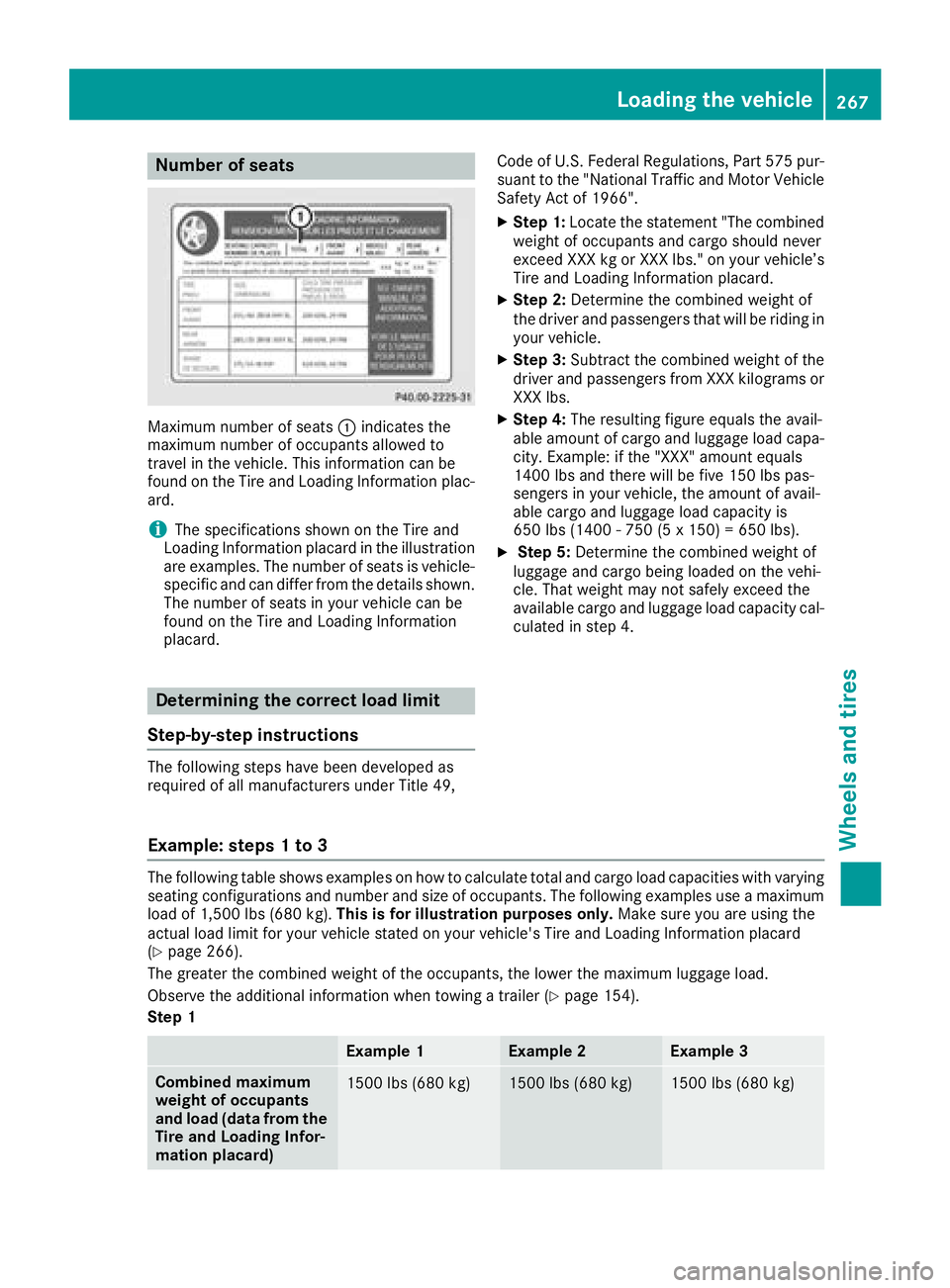
Maximum number of seats:indicates the
maximum number of occupants allowed to
travel in the vehicle. This information can be
found on the Tire and Loading Information plac-
ard.
iThe specifications shown on the Tire and
Loading Information placard in the illustration
are examples. The number of seats is vehicle-
specific and can differ from the details shown.
The number of seats in your vehicle can be
found on the Tire and Loading Information
placard.
Determining the correct load limit
Step-by-step instructions
The following steps have been developed as
required of all manufacturers under Title 49, Code of U.S. Federal Regulations, Part 575 pur-
suant to the "National Traffic and Motor Vehicle
Safety Act of 1966".
XStep 1: Locate the statement "The combined
weight of occupants and cargo should never
exceed XXX kg or XXX lbs." on your vehicle’s
Tire and Loading Information placard.
XStep 2: Determine the combined weight of
the driver and passengers that will be riding in your vehicle.
XStep 3: Subtract the combined weight of the
driver and passengers from XXX kilograms or
XXX lbs.
XStep 4: The resulting figure equals the avail-
able amount of cargo and luggage load capa-
city. Example: if the "XXX" amount equals
1400 lbs and there will be five 150 lbs pas-
sengers in your vehicle, the amount of avail-
able cargo and luggage load capacity is
650 lbs (1400 - 750 (5 x 150) = 650 lbs).
XStep 5: Determine the combined weight of
luggage and cargo being loaded on the vehi-
cle. That weight may not safely exceed the
available cargo and luggage load capacity cal- culated in step 4.
Example: steps 1 to 3
The following table shows examples on how to calculate total and cargo load capacities with varying
seating configurations and number and size of occupants. The following examples use a maximum
load of 1,500 lbs (680 kg). This is for illustration purposes only. Make sure you are using the
actual load limit for your vehicle stated on your vehicle's Tire and Loading Information placard
(
Ypage 266).
The greater the combined weight of the occupants, the lower the maximum luggage load.
Observe the additional information when towing a trailer (
Ypage 154).
Step 1
Example 1Example 2Example 3
Combined maximum
weight of occupants
and load (data from the
Tire and Loading Infor-
mation placard)1500 lbs (680 kg)1500 lbs (680 kg)1500 lbs (680 kg)
Loading the vehicle267
Wheels and tires
Z
Page 272 of 294
in combination, can cause excessive heat
build-up and possible tire failure.
The temperature grades are A (the highest), B,
and C, representing the tire's resistance to the
generation of heat and its ability to dissipate
heat when tested under controlled conditions
on a specified indoor laboratory test wheel. Sus-
tained high temperature can cause the material
of the tire to degenerate and reduce tire life, and
excessive temperature can lead to sudden tire
failure. The grade C corresponds to a level of
performance which all passenger car tires must
meet under the Federal Motor Vehicle Safety
Standard No. 109. Grades B and A represent
higher levels of performance on the laboratory
test wheel than the minimum required by law.
Tire labeling
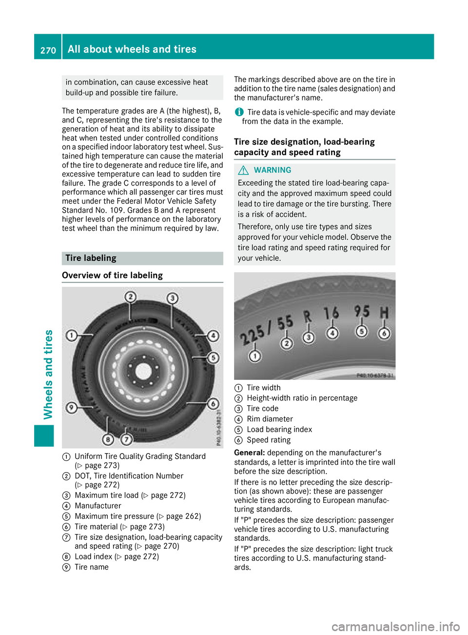
Overview of tire labeling
:Uniform Tire Quality Grading Standard
(Ypage 273)
;DOT, Tire Identification Number
(Ypage 272)
=Maximum tire load (Ypage 272)
?Manufacturer
AMaximum tire pressure (Ypage 262)
BTire material (Ypage 273)
CTire size designation, load-bearing capacity
and speed rating (Ypage 270)
DLoad index (Ypage 272)
ETire name The markings described above are on the tire in
addition to the tire name (sales designation) and
the manufacturer's name.
iTire data is vehicle-specific and may deviate
from the data in the example.
Tire size designation, load-bearing
capacity and speed rating
GWARNING
Exceeding the stated tire load-bearing capa-
city and the approved maximum speed could
lead to tire damage or the tire bursting. There is a risk of accident.
Therefore, only use tire types and sizes
approved for your vehicle model. Observe the
tire load rating and speed rating required for
your vehicle.
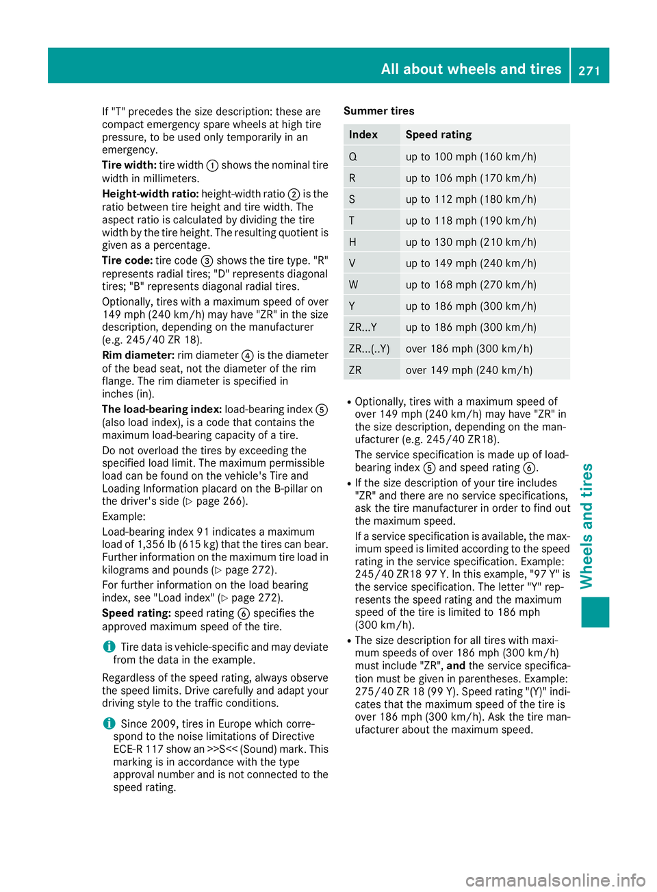
:Tire width
;Height-width ratio in percentage
=Tire code
?Rim diameter
ALoad bearing index
BSpeed rating
General: depending on the manufacturer's
standards, a letter is imprinted into the tire wall before the size description.
If there is no letter preceding the size descrip-
tion (as shown above): these are passenger
vehicle tires according to European manufac-
turing standards.
If "P" precedes the size description: passenger
vehicle tires according to U.S. manufacturing
standards.
If "P" precedes the size description: light truck
tires according to U.S. manufacturing stand-
ards.
270All about wheels and tires
Wheels and tires
Page 273 of 294
If "T" precedes the size description: these are
compact emergency spare wheels at high tire
pressure, to be used only temporarily in an
emergency.
Tire width:tire width:shows the nominal tire
width in millimeters.
Height-width ratio: height-width ratio;is the
ratio between tire height and tire width. The
aspect ratio is calculated by dividing the tire
width by the tire height. The resulting quotient is
given as a percentage.
Tire code: tire code=shows the tire type. "R"
represents radial tires; "D" represents diagonal
tires; "B" represents diagonal radial tires.
Optionally, tires with a maximum speed of over
149 mph (240 km/h) may have "ZR" in the size
description, depending on the manufacturer
(e.g. 245/40 ZR 18).
Rim diameter: rim diameter?is the diameter
of the bead seat, not the diameter of the rim
flange. The rim diameter is specified in
inches (in).
The load-bearing index: load-bearing indexA
(also load index), is a code that contains the
maximum load-bearing capacity of a tire.
Do not overload the tires by exceeding the
specified load limit. The maximum permissible
load can be found on the vehicle's Tire and
Loading Information placard on the B-pillar on
the driver's side (
Ypage 266).
Example:
Load-bearing index 91 indicates a maximum
load of 1,356 lb (615 kg) that the tires can bear.
Further information on the maximum tire load in
kilograms and pounds (
Ypage 272).
For further information on the load bearing
index, see "Load index" (
Ypage 272).
Speed rating: speed ratingBspecifies the
approved maximum speed of the tire.
iTire data is vehicle-specific and may deviate
from the data in the example.
Regardless of the speed rating, always observe
the speed limits. Drive carefully and adapt your driving style to the traffic conditions.
iSince 2009, tires in Europe which corre-
spond to the noise limitations of Directive
ECE-R 117 show an >>S<< (Sound) mark. This
marking is in accordance with the type
approval number and is not connected to the
speed ra
ting. Summer tires
IndexSpeed rating
Qup to 100 mph (160 km/h)
Rup to 106 mph (170 km/h)
Sup to 112 mph (180 km/h)
Tup to 118 mph (190 km/h)
Hup to 130 mph (210 km/h)
Vup to 149 mph (240 km/h)
Wup to 168 mph (270 km/h)
Yup to 186 mph (300 km/h)
ZR...Yup to 186 mph (300 km/h)
ZR...(..Y)over 186 mph (300 km/h)
ZRover 149 mph (240 km/h)
ROptionally, tires with a maximum speed of
over 149 mph (240 km/h) may have "ZR" in
the size description, depending on the man-
ufacturer (e.g. 245/40 ZR18).
The service specification is made up of load-
bearing index
Aand speed rating B.
RIf the size description of your tire includes
"ZR" and there are no service specifications,
ask the tire manufacturer in order to find out
the maximum speed.
If a service specification is available, the max-
imum speed is limited according to the speed
rating in the service specification. Example:
245/40 ZR18 97 Y.In this example, "97 Y" is
the service specification. The letter "Y" rep-
resents the speed rating and the maximum
speed of the tire is limited to 186 mph
(300 km/h).
RThe size description for all tires with maxi-
mum speeds of over 186 mph (300 km/h)
must include "ZR", andthe service specifica-
tion must be given in parentheses. Example:
275/40 ZR 18 (99 Y). Speed rating "(Y)" indi-
cates that the maximum speed of the tire is
over 186 mph (300 km/h). Ask the tire man-
ufacturer about the maximum speed.
All about wheels and tires271
Wheels and tires
Z
Page 276 of 294
Recommended tire pressures
The recommended tire pressure applies to the
tires mounted at the factory.
The Tire and Loading Information placard con-
tains the recommended tire pressures for cold
tires on a fully loaded vehicle and for the maxi-
mum permissible vehicle speed.
The tire pressure table contains the recommen-ded pressures for cold tires for various operat-
ing conditions, i.e. differing load and speed con- ditions.
Increased vehicle weight due to optional
equipment
The combined weight of all standard and
optional equipment available for the vehicle,
regardless of whether it is actually installed on
the vehicle or not.
Rim
This is the part of the wheel on which the tire is
mounted.
GAWR (Gross Axle Weight Rating)
The GAWR is the maximum gross axle weight
rating. The actual load on an axle must never
exceed the gross axle weight rating. The gross
axle weight rating can be found on the vehicle
identification plate on the B-pillar on the driver's
side.
Speed rating
The speed rating is part of the tire identification.It specifies the speed range for which the tire is
approved.
GTW (Gross Trailer Weight)
The GTW is the weight of a trailer including the
weight of the load, luggage, accessories etc. onthe trailer.
GVW (Gross Vehicle Weight)
The gross vehicle weight includes the weight of
the vehicle including fuel, tools, the spare wheel,
accessories installed, occupants, luggage and
the drawbar noseweight, if applicable. The gross
vehicle weight must not exceed the gross vehi-
cle weight rating GVWR as specified on the vehi-
cle identification plate on the B-pillar on the
driver's side.
GVWR (Gross Vehicle Weight Rating)
The GVWR is the maximum permissible gross
weight of a fully loaded vehicle (the weight of the
vehicle including all accessories, occupants,
fuel, luggage and the drawbar noseweight, if
applicable). The gross vehicle weight rating is
specified on the vehicle identification plate on
the B-pillar on the driver's side.
Maximum loaded vehicle weight
The maximum weight is the sum of:
Rthe curb weight of the vehicle
Rthe weight of the accessories
Rthe load limit
Rthe weight of the factory installed optional
equipment
Kilopascal (kPa)
Metric unit for tire pressure. 6.9 kPa corre-
sponds to 1 psi. Another unit for tire pressure is
bar. 100 kilopascals (kPa) are the equivalent of
1 bar.
Load index
In addition to the load-bearing index, the load
index may also be imprinted on the sidewall of
the tire. This specifies the load-bearing capacity
of the tire more precisely.
Curb weight
The weight of a vehicle with standard equipment
including the maximum capacity of fuel, oil and
coolant. It also includes the air-conditioning sys-
tem and optional equipment if these are instal-
led in the vehicle, but does not include passen-
gers or luggage.
Maximum load rating
The maximum tire load is the maximum permis-
sible weight in kilograms or lbs for which a tire is
approved.
Maximum permissible tire pressure
Maximum permissible tire pressure for one tire.
Maximum load on one tire
Maximum load on one tire. This is calculated by dividing the maximum axle load of one axle by
two.
274All about wheels and tires
Wheels and tires
Page 279 of 294
Observe the following when raising the vehi-
cle:
RTo raise the vehicle, only use the vehicle-spe-
cific jack that has been tested and approved
by Mercedes-Benz. If used incorrectly, the
jack could tip over with the vehicle raised.
RThe jack is designed only to raise and hold the
vehicle for a short time while a wheel is being
changed. It must not be used for performing
maintenance work under the vehicle.
RAvoid changing the wheel on uphill and down-
hill slopes.
RBefore raising the vehicle, secure it from roll-
ing away by applying the parking brake and
inserting wheel chocks. Do not disengage the
parking brake while the vehicle is raised.
RThe jack must be placed on a firm, flat and
non-slip surface. On a loose surface, a large,
flat, load-bearing underlay must be used. On a
slippery surface, a non-slip underlay must be
used, e.g. rubber mats.
RDo not use wooden blocks or similar objects
as a jack underlay. Otherwise, the jack will not
be able to achieve its load-bearing capacity
due to the restricted height.
RMake sure that the distance between the
underside of the tires and the ground does not
exceed 1.2 in (3 cm).
RDo not place your hands or feet under the
raised vehicle.
RDo not lie under the vehicle.
RDo not start the engine when the vehicle is
raised.
RDo not open or close a door when the vehicle is raised.
RMake sure that no persons are present in the
vehicle when the vehicle is raised.
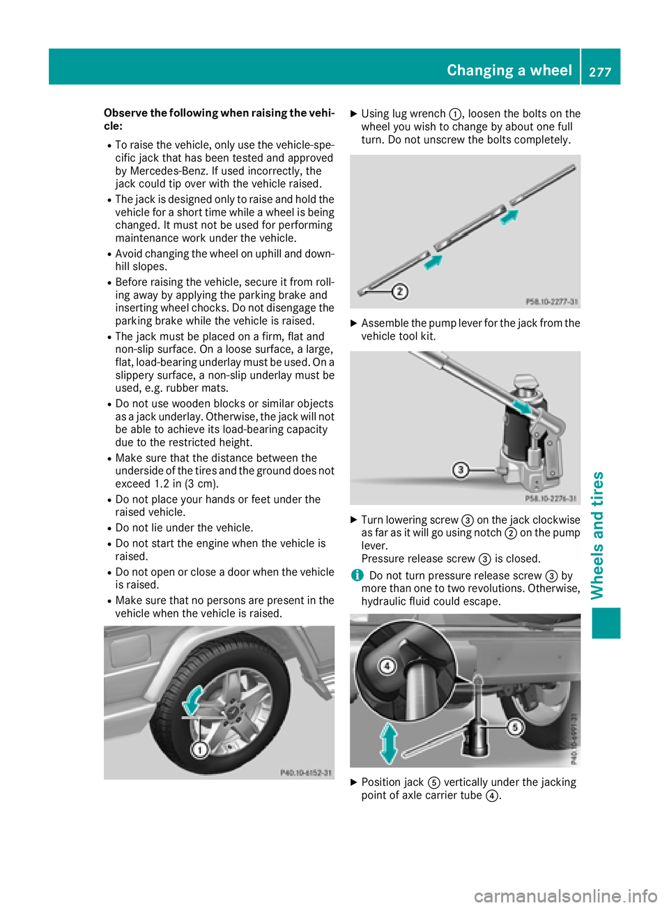
XUsing lug wrench :, loosen the bolts on the
wheel you wish to change by about one full
turn. Do not unscrew the bolts completely.
XAssemble the pump lever for the jack from the vehicle tool kit.
XTurn lowering screw =on the jack clockwise
as far as it will go using notch ;on the pump
lever.
Pressure release screw =is closed.
iDo not turn pressure release screw =by
more than one to two revolutions. Otherwise,
hydraulic fluid could escape.
XPosition jack Avertically under the jacking
point of axle carrier tube ?.
Changing a wheel277
Wheels and tires
Z